EP0236094A2 - Ausarbeitungsmaschine - Google Patents
Ausarbeitungsmaschine Download PDFInfo
- Publication number
- EP0236094A2 EP0236094A2 EP87301767A EP87301767A EP0236094A2 EP 0236094 A2 EP0236094 A2 EP 0236094A2 EP 87301767 A EP87301767 A EP 87301767A EP 87301767 A EP87301767 A EP 87301767A EP 0236094 A2 EP0236094 A2 EP 0236094A2
- Authority
- EP
- European Patent Office
- Prior art keywords
- finishing
- media
- workpiece
- container
- chamber
- Prior art date
- Legal status (The legal status is an assumption and is not a legal conclusion. Google has not performed a legal analysis and makes no representation as to the accuracy of the status listed.)
- Withdrawn
Links
- 230000002093 peripheral effect Effects 0.000 claims abstract description 22
- 230000033001 locomotion Effects 0.000 claims abstract description 20
- 239000000203 mixture Substances 0.000 claims description 13
- 230000000694 effects Effects 0.000 description 3
- 230000015572 biosynthetic process Effects 0.000 description 2
- 238000009499 grossing Methods 0.000 description 2
- 239000000463 material Substances 0.000 description 2
- 229920003023 plastic Polymers 0.000 description 2
- 239000004033 plastic Substances 0.000 description 2
- 230000005540 biological transmission Effects 0.000 description 1
- 239000000919 ceramic Substances 0.000 description 1
- 229920002635 polyurethane Polymers 0.000 description 1
- 239000004814 polyurethane Substances 0.000 description 1
Images

Classifications
-
- B—PERFORMING OPERATIONS; TRANSPORTING
- B24—GRINDING; POLISHING
- B24B—MACHINES, DEVICES, OR PROCESSES FOR GRINDING OR POLISHING; DRESSING OR CONDITIONING OF ABRADING SURFACES; FEEDING OF GRINDING, POLISHING, OR LAPPING AGENTS
- B24B31/00—Machines or devices designed for polishing or abrading surfaces on work by means of tumbling apparatus or other apparatus in which the work and/or the abrasive material is loose; Accessories therefor
- B24B31/06—Machines or devices designed for polishing or abrading surfaces on work by means of tumbling apparatus or other apparatus in which the work and/or the abrasive material is loose; Accessories therefor involving oscillating or vibrating containers
Definitions
- This invention relates to finishing apparatus, and is particularly concerned with finishing apparatus of the type in which a workpiece and finishing media are agitated together in a finishing chamber.
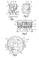
- Fig.1 is a cross section through a vibratory finishing machine on line I - I in the plan view in Fig.2.
- the machine comprises a recangular container 10 having flat side walls 9 and a semi-circular bottom wall 12.
- the container is mounted resiliently on a base 13 through springs 14.
- An electric motor 15 is mounted on a plate 16 carried beneath the container and has a drive spindle 17.
- the spindle 17 carries eccentric weights 18.
- the container holds suitable finishing media 19, (e.g. cones of ceramic or plastics material) and workpieces 20. With the electric motor 15 running, the eccentric weights 18 vibrate the container 10 thereby causing the media and workpieces to undergo a rotary motion as indicated by arrows A in Figs. 1 and 2.
- the media 19 has an abrasive action on the workpieces 20 and smooths the workpieces. Even with the largest machines of this type, e.g. measuring 4m x 1.25 m in plan, it is difficult to effect smoothing of large workpieces, e.g. a workpiece that would occupy more than 50 % of the plan area of the container as such workpieces tend to "ride" on top of the m edia and are generally pushed to one side as indicated at 21 unless held in a desired postion by a jig. If the rectangular container is made bigger in plan area to accommodate larger workpieces, the rotary movement of the media diminishes substantially or disappears completely and the effectiveness of the media to provide overall smoothing of the workpiece is reduced.
- FIG. 3 is a diametrical cross-section through the machine on line III - III in the plan view in Fig.4.
- Machines of this type are shown in my GB Patents Nos. 2098109 and 2102316 and comprise a container 30 having a cylindrical outer wall 32, a cylindrical inner wall 33 and an annular bottom wall 34 of semi-circular cross section. The walls define an annular finishing chamber 31 between them.
- the container is resiliently mounted on a base 35 through circumferentially spaced springs 36.
- An electric motor 37 is mounted on a plate 38 beneath the container 30 and has a drive spindle 39 carrying two eccentric weights 40.
- the spindle 39 of motor 37 is vertical and is housed partly within a space 42 defined by the inner wall 33.
- running of the motor causes the eccentric weights to vibrate the container 31 and a mixture of media 43 and workpieces 44 in the chamber.
- the mixture in the machine of Figs. 3 and 4 follows a helical path as indicated in broken lines in Fig.4 resulting from a radial rotation R combined with a circumferential movement C.
- the largest machine of this kind known to me has a finishing chamber width W of around 80 cm e.g.
- a workpiece e.g.
- a plate-like workpiece 45 indicated in broken lines in Figs. 3 and 4) having a dimension exceeding the width W is normally regarded as being too large to smooth in such a machine.
- Such workpieces have a tendency to "ride" on top of the media and are pushed against the inner wall. Therefore even the largest machines of this type known to me could not normally be used successfully to smooth plate-like workpieces having a dimension greater than 80 cm.
- An object of the present invention is to provide a finishing machine which can accommodate large workpieces without the attendant disadvantages of the machines shown in Figs. 1 to 4.
- the workpiece does not, therefore, ride on top of the media as in the prior art.
- the uninterrupted finishing chamber lends itself to receiving much larger workpieces than the annular type of finishing chamber having a peripheral wall of the same diameter.
- finishing apparatus comprising a container having an upstanding peripheral wall surrounding a finishing chamber for a mixture comprising finishing media and a workpiece, and drive means for imparting vibratory movement to the container so as to agitate the mixture and cause at least part of the media to follow a helical path in the finishing chamber, the finishing chamber being substantially uninterupted between directly opposite portions of the peripheral wall.
- finishing apparatus comprising a container having an upstanding peripheral wall surrounding a finishing chamber, a mixture comprising finishing media and a workpiece in said finishing chamber and means imparting vibratory movment to said container, said finishing chamber being substantially uninterrupted between directly opposite portions of the peripheral wall and the workpiece being spaced from the peripheralwall by the vibrating media, the media moving over an upwardly facing surface of the workpiece due to the vibratory movement.
- the finishing chamber has a bottom surface a major part of which is flat.
- the flat bottom surface and the peripheral wall may be joined by an intermediate curved wall section.
- the curve may be a quarter circle in cross section giving a part torroidal formation at the bottom of the peripheral wall. Such a curved formation enhances the movement of the media.
- approximately75% of the plan area of the finishing chamber has the flat bottom surface.
- the vibrating movement imparted by the drive means causes, in use, at least some of the finishing media to follow a helical path around the finishing chamber .
- the above curved section assists the media to move from the flat bottom surface upwardly into engagement with the wall or vice-versa during the vibratory movement.
- the entire means for vibrating the container e.g. an electric motor and eccentric weight arrangement, may be arranged beneath the lowest portion of the container or to one side thereof.
- the means for imparting vibratory movement comprises a weight arranged eccentrically on a rotatable shaft, e.g. a rotatable vertical shaft, and positioned eg adjacent said bottom surface of the container.
- the shaft may be a drive shaft of a motor.
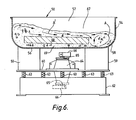
- the finishing apparatus in Figs. 5 and 6 comprises a cylindrical container 50 having a single upstanding peripheral wall 54 a flat bottom wall 56 and an intermediate curved wall portion 58 which is of quadrant cross section giving a smooth torroidal-like section at the lower end of wall 54.
- a finishing chamber 57 is defined between the wall 54, wall 56 and wall portion 58.
- the finishing chamber 57 is uninterrupted between diametrically opposite sections due to the absence of a cylindrical inner wall.
- the container is therefore a U-shaped bowl in cross section as seen in Fig.5.
- the container 50 is rigidly fixed via arms 59 to a supporting plate 60.
- the plate is resiliently mounted on a ground engaging base 62 by springs 63 which are circumferentially spaced around plate 60.
- An electric motor 64 having a central drive spindle 65 with eccentric weights 66 mounted thereon is rigidly mounted on the plate 60. The motor and weights are positioned completely beneath the bottom wall 56. One weight 66 may be heavier then the other if desired and their relative angular positions (preferably 90° out of phase) may be adjustable to vary vibration characteristics.
- finising media 67 and a single large workpiece 68 are placed in the finishing chamber 57.
- the eccentric weights 66 cause the container 50 to vibrate.
- the vibration agitates the finishing media 67 and the workpiece 68 therein.
- Initial upward movement of the media from the flat bottom wall 56 and along the curved section 58 has the effect of spacing the workpiece from the wall 57.
- the vibrating media gradually moves from beneath the workpiece causing it to sink deeper into the media until it comes to rest on a layer 69 of vibrating media adjacent the flat bottom wall 56.
- the workpiece remains substantially at that level in the media.
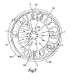
- the workpiece shown is a circular plate 58.
- the media circulates substantially as shown by arrows.
- the media tends to urge the plate to a slightly off-centre position as shown in Fig.5 and the media in the gap between the wall 54 and plate 68 over arc 100 undergoes a helical action as shown by arrows A causing media to build up over arc 101 to a higher level.
- the media from that area then moves substantially linearly across the upper surface of the workpiece as shown by arrows A ⁇ .
- the media moves en masse circumferentially and the plate is carried around (spaced from wall 54) by the media.
- the continual abrasive action of the vibrating media 56 on the upper, lower and edge surfaces of the workpiece 68 has the effect of removing burrs from the surfaces.
- the media generates inward forces F on the plate which maintains it spaced all round from the wall 54.
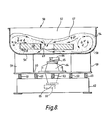
- the workpice comprises a circular plate 68 formed with alarge central aperture 69.
- the plate again is moved off centre by the vibrating media which spaces it from the wall 54.
- Media in the space between the plate 68 and the wall 54 over arc 100 again circulates helically as indicated by arrows A causing a build up of media over arc 101.
- Media from the regions of arcs 100 and 101 also travels towards the aperture 69 as indicated by arrows A ⁇ and a circulation of the media through the aperture and beneath the plate takes place as shown by the arrows.
- the media again applies inward forces F on the plate which maintain it spaced all round from the wall 54.
- finishing chamber Although one large workpiece is illustrated in the finishing chamber, it is envisaged that several smaller workpieces may be placed therein. Also workpieces of shapes other than circular can be smoothed in the finishing chamber.
- the motor and eccentric weights which vibrate the container 14 may be replaced by other vibratory means. Additionally, it is contemplated that the motor 30 may be located to one side of the container and connected to a weight carrying spindle on the container by a suitable drive transmission. The rate of vibration may be controlled by varying the speed of the motor 30.
- finishing chamber 57 will hold workpieces which extend from a position adjacent one portion of the wall 54 to a position beyond the middle of the chamber and the machine is most advantageous in that respect.
- the flat bottom wall 56 constitutes approximately 75% of the total plan area of the finishing chamber as viewed in Figs. 6 and 8.
- the inner surfaces of the container will be coated with plastics materials, e.g. polyurethane, to give protection against wear.
- the preferred diameter of the finishing chamber is around 165 cm although it is envisaged that larger diameter chambers could be used.
Landscapes
- Engineering & Computer Science (AREA)
- Mechanical Engineering (AREA)
- Finish Polishing, Edge Sharpening, And Grinding By Specific Grinding Devices (AREA)
Applications Claiming Priority (2)
| Application Number | Priority Date | Filing Date | Title |
|---|---|---|---|
| GB868604898A GB8604898D0 (en) | 1986-02-27 | 1986-02-27 | Finishing apparatus |
| GB8604898 | 1986-02-27 |
Publications (2)
| Publication Number | Publication Date |
|---|---|
| EP0236094A2 true EP0236094A2 (de) | 1987-09-09 |
| EP0236094A3 EP0236094A3 (de) | 1988-12-21 |
Family
ID=10593777
Family Applications (1)
| Application Number | Title | Priority Date | Filing Date |
|---|---|---|---|
| EP87301767A Withdrawn EP0236094A3 (de) | 1986-02-27 | 1987-02-27 | Ausarbeitungsmaschine |
Country Status (2)
| Country | Link |
|---|---|
| EP (1) | EP0236094A3 (de) |
| GB (2) | GB8604898D0 (de) |
Families Citing this family (1)
| Publication number | Priority date | Publication date | Assignee | Title |
|---|---|---|---|---|
| RU2342243C2 (ru) * | 2007-02-06 | 2008-12-27 | Открытое акционерное общество "Национальный институт авиационных технологий" (ОАО "НИАТ") | Способ виброударной обработки поверхностей тонкостенных деталей |
Family Cites Families (3)
| Publication number | Priority date | Publication date | Assignee | Title |
|---|---|---|---|---|
| US3570192A (en) * | 1969-02-24 | 1971-03-16 | Ultramatic Equipment Co | Vibratory finishing machine having generally circular bowl |
| SU679378A2 (ru) * | 1977-11-01 | 1979-08-15 | Предприятие П/Я Р-6877 | Вибрационна установка |
| SU1196234A1 (ru) * | 1984-04-09 | 1985-12-07 | Предприятие П/Я Р-6877 | Устройство дл вибрационной обработки |
-
1986
- 1986-02-27 GB GB868604898A patent/GB8604898D0/en active Pending
-
1987
- 1987-02-27 GB GB08704681A patent/GB2187122A/en not_active Withdrawn
- 1987-02-27 EP EP87301767A patent/EP0236094A3/de not_active Withdrawn
Also Published As
| Publication number | Publication date |
|---|---|
| EP0236094A3 (de) | 1988-12-21 |
| GB8704681D0 (en) | 1987-04-01 |
| GB2187122A (en) | 1987-09-03 |
| GB8604898D0 (en) | 1986-04-03 |
Similar Documents
| Publication | Publication Date | Title |
|---|---|---|
| US3877178A (en) | Vibratory finishing machine | |
| US6210259B1 (en) | Method and apparatus for lapping of workpieces | |
| US3464674A (en) | Vibrator | |
| US3991524A (en) | Vibratory finishing equipment | |
| EP0236094A2 (de) | Ausarbeitungsmaschine | |
| US6210258B1 (en) | Vibrational finishing assembly | |
| US3197922A (en) | Apparatus for agitating and polishing materials | |
| JPS5933412B2 (ja) | 製品処理方法及び装置 | |
| US3213568A (en) | Corrugated bowl lining for vibrators | |
| FI81029B (fi) | Gravitationsseparation. | |
| US4520598A (en) | Bowl-type vibratory finishing machine | |
| US4452016A (en) | Reversing weight for vibrating finishing machines | |
| US4905416A (en) | Reversing weight assembly for a vibratory bowl finishing machine | |
| US3708918A (en) | Agitator for moving fluid suspended objects through abrasive motions | |
| CA2288590C (en) | Method and apparatus for lapping of workpieces | |
| RU2162365C1 (ru) | Вибрационный смеситель | |
| US3943668A (en) | Vibratory mill structure | |
| US4001984A (en) | Method for finishing parts | |
| RU2703065C1 (ru) | Способ центробежной абразивной обработки колец подшипников качения | |
| US4201017A (en) | Methods and apparatus for the treatment of products | |
| CA2290057C (en) | Vibrational finishing assembly | |
| JPS6236097Y2 (de) | ||
| US3195279A (en) | Tumbling barrel and drive therefor | |
| SU1166972A1 (ru) | Способ обработки изделий в сыпучих или жидких абразивных средах | |
| SU1210892A1 (ru) | Центробежное устройство дл обогащени тонкоизмельченных материалов и шламов |
Legal Events
| Date | Code | Title | Description |
|---|---|---|---|
| PUAI | Public reference made under article 153(3) epc to a published international application that has entered the european phase |
Free format text: ORIGINAL CODE: 0009012 |
|
| AK | Designated contracting states |
Kind code of ref document: A2 Designated state(s): AT BE CH DE ES FR GB GR IT LI LU NL SE |
|
| PUAL | Search report despatched |
Free format text: ORIGINAL CODE: 0009013 |
|
| AK | Designated contracting states |
Kind code of ref document: A3 Designated state(s): AT BE CH DE ES FR GB GR IT LI LU NL SE |
|
| STAA | Information on the status of an ep patent application or granted ep patent |
Free format text: STATUS: THE APPLICATION IS DEEMED TO BE WITHDRAWN |
|
| 18D | Application deemed to be withdrawn |
Effective date: 19890622 |