EP0235895B2 - Improvements in or relating to electric radiation heater assemblies - Google Patents
Improvements in or relating to electric radiation heater assemblies Download PDFInfo
- Publication number
- EP0235895B2 EP0235895B2 EP87300513A EP87300513A EP0235895B2 EP 0235895 B2 EP0235895 B2 EP 0235895B2 EP 87300513 A EP87300513 A EP 87300513A EP 87300513 A EP87300513 A EP 87300513A EP 0235895 B2 EP0235895 B2 EP 0235895B2
- Authority
- EP
- European Patent Office
- Prior art keywords
- heating elements
- assembly
- resistance
- electrically connected
- parallel
- Prior art date
- Legal status (The legal status is an assumption and is not a legal conclusion. Google has not performed a legal analysis and makes no representation as to the accuracy of the status listed.)
- Expired - Lifetime
Links
Images


Classifications
-
- H—ELECTRICITY
- H05—ELECTRIC TECHNIQUES NOT OTHERWISE PROVIDED FOR
- H05B—ELECTRIC HEATING; ELECTRIC LIGHT SOURCES NOT OTHERWISE PROVIDED FOR; CIRCUIT ARRANGEMENTS FOR ELECTRIC LIGHT SOURCES, IN GENERAL
- H05B3/00—Ohmic-resistance heating
- H05B3/68—Heating arrangements specially adapted for cooking plates or analogous hot-plates
- H05B3/74—Non-metallic plates, e.g. vitroceramic, ceramic or glassceramic hobs, also including power or control circuits
- H05B3/742—Plates having both lamps and resistive heating elements
Definitions
- the present invention relates to electric radiation heater assemblies for glass ceramic top cookers.
- ballast coil In order to reduce these problems it is known to connect a bare wire resistance coil, known as a ballast coil, in series with the infra-red lamp or lamps. If the power consumed by such a ballast coil is significant, i.e. more than a few per cent of the total power consumed by the heater, it is considered essential to position the ballast coil within the body of the heater. In practice, the power consumed by the ballast coil is typically one third of the total power. This eliminates the problems with magnetic circuit breakers and reduces mains disturbances to an acceptable level with relatively low power heaters i.e. up to about 1500 watts.
- EP-A-0 164 900 discloses a heating unit for a cooking hob which may include an additional heating element.
- the additional heating element serves two purposes. One purpose is to enable low power settings to be achieved without resorting to the use of diodes, and in this respect the additional heating element is permanently connected in series with the configuration formed by the remaining lamp filaments at two power settings.
- the other purpose is as a pre-heating device to produce faster warmup periods, and in this respect the use of the additional heating element provides a high power output for an initial warm-up period, the length of which may be controlled by a timer and/or thermal sensor device.
- US-A-3 017 564 dlsdoses a protective circuit in which current-limiting means in the form of a thermistor having a negative temperature coefficient of resistance is temporarily connected in series with the load.
- Two relay coils in series with the load are associated with relay contacts which control the operation of a shunt circuit around the thermistor.
- the shunt circuit is normally open, but doses when the resistance of the thermistor decreases sufficiently, allowing the thermistor to cool for subsequent energisation of the load.
- Such a circuit is unsuited to the substitution of a ballast coil for the thermistor.
- DE-C-1 120 013 describes a circuit arrangement for reducing the starting current of filament lamps, particularly projector lamps, according to which a series-connected ballast resistor is short-circuited by a relay after a few milliseconds.
- an electric radiation heater assembly comprising: first and second heating elements having a substantial positive temperature coefficient of resistance, the first and second heating elements being electrically connected in parallel; a resistive assembly, comprising first and second resistances electrically connected in parallel, the resistive assembly being electrically connected in series with the parallel arrangement of the first and second heating elements for suppressing surge of electric current due to the first and second heating elements; and relay switch means comprising a switch electrically connected in series with one of said first and second resistances and operable to close after a time interval of at least 30 milliseconds following energisation of the heater assembly so as to reduce the combined electrical resistance of said first and second heating elements and said resistive assembly, the switch means further comprising an actuating coil which is connected in parallel and energised simultaneously with said first and second heating elements.
- an electric radiation heater assembly comprising: first and second heating elements having a substantial positive temperature coefficient of resistance, the first and second heating elements being electrically connected in parallel; a resistive assembly, comprising first and second resistances, the resistive assembly being electrically connected in series with the parallel arrangement of the first and second heating elements for suppressing surge of electric current due to the first and second heating elements; and relay switch means comprising a switch operable after a time interval of at least 30 milliseconds following energisation of the heater assembly so as to reduce the combined electrical resistance of said first and second heating elements and said resistive assembly, the switch means further comprising an actuating coil which is connected in parallel and energised simultaneously with said first and second heating elements, and first and second switches adapted initially to connect the first and second resistances electrically in series with one another and, following operation of the switch means, subsequently to connect the first and second resistances electrically in parallel with one another.
- an electric radiation heater assembly comprising: first and second heating elements having a substantial positive temperature coefficient of resistance; a resistive assembly, comprising a first resistance electrically connected in series with the first heating element and a second resistance electrically connected in series with the second heating element, for suppressing surge of electric current due to the first and second heating elements; and relay switch means comprising a switch electrically connected in series with one of said first and second heating elements and operable after a time interval of at least 30 milliseconds following energisation of the heater assembly so as to reduce the combined electrical resistance of said first and second heating elements and said resistive assembly, the switch means further comprising an actuating coil which is connected in parallel and energised simultaneously with said first and second heating elements.
- the or each heating element may comprise an infra-red lamp.
- the time interval generated by the switch means may be from 30 milliseconds to 10 seconds, but is preferably about 1/2 second.
- the circuit depicted by means of the circuit diagram shown in Figure 1 comprises an energy regulator 1, a time delay means 2 which is connected to the output side of the energy regulator 1 and which operates a switch 3 a predetermined time after each occasion the energy regulator permits electric current to pass therethrough, a pair of resistors 4,5 each in the form of a coil of bare resistance wire, a pair of infra-red lamps 6,7 which are electrically connected in parallel, and a thermal cut-out device 8.
- the energy regulator 1 is moved from an "of" position to an infinitely variable "on” position in which for higher settings the energy regulator permits electric current to pass therethrough for a greater proportion of a given period.
- the time delay means to the switch 3 and to one of the resistors 5.
- Current flows through the resistor 5 through the lamps 6,7 which are connected in parallel and back to the energy regulator 1.
- the time delay means 2 operates to close the switch 3 and thus allows current to pass through resistor 4. Because resistors 4,5 are now connected in parallel this effectively halves their combined resistance and causes the electric current flowing through the lamps 6,7 to increase.
- the time delay may vary considerably. However, if the time delay is very short, i.e, less than 30 milliseconds, the lamps will effectively be energised simultaneously thus not reducing any mains disturbance that might arise, whilst if the time delay is much more than 10 seconds one of the resistors 4 will be energised for a significantly shorter period than the other resistor at low settings of the energy regulator. In practice, we have found that a time delay of about 1/2 second is to be preferred.
- the radiant heater shown in Figure 2 embodies the circuit diagram of Figure 1 and comprises a dish 10, for example pressed from sheet metal, which contains a base layer 11 of thermal and electrical insulating material and a peripheral wall 12 of thermal insulating material.
- a helical coil of bare resistance wire is arranged on the base layer and extends substantially in a circle adjacent fo the peripheral wall 12. The coil is centre-tapped to form two resistance elements 13,14.
- a thermal cut-out device 15 extends across substantially the centre of the dish 10 and comprises a temperature sensor 16 connected to a switch 17. In the event that the temperature sensor 16 detects an excessive temperature the switch 17 is actuated to de-energise the heating elements until such time as the temperature has dropped to an acceptable level.
- Two infra-red lamps 18,19 extend across the dish 10, one lamp being positioned on each side of the temperature sensor 16.
- A.C. power is supplied to the resistance elements 13,14 and to the infra-red lamps 18,19 by way of an energy regulator 20 and, in the case of resistance element 13, a switch 21.
- Switch 21 is connected to a time delay mechanism 22.
- the lamps 18,19 are typically rated at 600 watts at 147 volts each, with the resistance elements 13,14 rated at 17.9 ohms each with the resistance wire at its operating temperature. This arrangement results in approximately 67 per cent of the energy being derived from the infra-red lamps 18,19.
- the circuit depicted by means of the circuit diagram shown in Figure 3 comprises an energy regulator 31 and a time delay means 32 which is connected to the output side of the energy regulator 31 and which operates switches 33,34 a predetermined time after each occasion the energy regulator permits electric current to pass therethrough.
- a resistive assembly comprises a pair of resistors 35,36 each in the form of a coil of bare resistance wire which are connected with the switches 33,34 so as to be electrically connected in series and in parallel as will be explained in more detail hereinafter.
- a pair of infra-red lamps 37,38 are electrically connected in parallel with each other and in series with the resistive assembly.
- a thermal cut-out device 39 is electrically connected in series with the lamps 37,38 for preventing excessive temperatures.
- Operation of the circuit depicted in Figure 3 is similar to the operation of the circuit depicted in Figure 1 except that initially the two resistors 35,36 are connected in series and the delay means 32 operates switches 33,34 to connect the resistors 35,36 in parallel.
- This arrangement has the advantage of increasing the initial resistance compared with the circuit depicted in Figure 1, but a double-pole changeover switch is required and the switches are required to break a current and will therefore need to be heavier duty.
- the circuit depicted in Figure 4 comprises an energy regulator 41 and a time delay means 42 which is connected to the output of the energy regulator and which operates switch 43 a predetermined time after each occasion the energy regulator permits current to pass.
- the energy regulator is conductive electric current passes through resistor 45, infra-red lamp 47, and thermal cutout device 48 and after a pre-determined delay switch 43 is closed and causes resistor 44 and lamp 46 to be connected in parallel with resistor 45 and infra-red lamp 47.
- the lamps 46,47 are energised separately which further suppresses the inrush current, but two separate resistors are required rather than a single centre-tapped resistor.
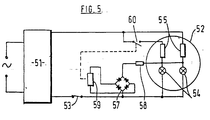
- FIG. 5 shows an energy regulator 51 which is electrically connected with heating elements in a heater dish 52 by way of a thermal cut-out device 53.
- the heating elements include two infra-red lamps 54, although in the embodiment of Figure 5 two coils 55 of resistance wire are also provided.
- the electrical voltage across the infra-red lamps 54 is passed to a rectifier 57 by way of a resistor 58.
- the rectified voltage is applied to the coil 59 of a relay which incorporates a switch 60.
- applying voltage to the relay coil 59 causes the relay switch 60 to close. This results in the coils 55 being connected in parallel and thus reduces the combined resistance of the coils 55 and the infra-red lamps 54.
- the switch means may be an integral part of a terminal block which supplies electric current to the heating elements within the heater or may be mounted within the cooker hob or its control unit as a separate assembly.
Abstract
Description
- The present invention relates to electric radiation heater assemblies for glass ceramic top cookers.
- It is known that the use of heating elements with high operating temperatures, such as infra-red lamps, in glass ceramic top cookers gives rise to an improvement in cooking performance as a result of improved radiant heat transfer, fast response to changes in control settings and visual feedback of the control setting. However, because of the large positive temperature coefficient of resistance associated with infra-red lamps, the initial or inrush current is very high and this can cause problems such as triping of magnetic circuit breakers and mains disturbances.
- In order to reduce these problems it is known to connect a bare wire resistance coil, known as a ballast coil, in series with the infra-red lamp or lamps. If the power consumed by such a ballast coil is significant, i.e. more than a few per cent of the total power consumed by the heater, it is considered essential to position the ballast coil within the body of the heater. In practice, the power consumed by the ballast coil is typically one third of the total power. This eliminates the problems with magnetic circuit breakers and reduces mains disturbances to an acceptable level with relatively low power heaters i.e. up to about 1500 watts. However, higher power heaters can still result in unacceptable disturbances to the mains electricity unless the resistance of the ballast coil is increased, but increasing the resistance of the ballast coil reduces the advantages of using infra-red lamps because it reduces the proportion of the power of the heater generated by the lamps.
- EP-A-0 164 900 discloses a heating unit for a cooking hob which may include an additional heating element. The additional heating element serves two purposes. One purpose is to enable low power settings to be achieved without resorting to the use of diodes, and in this respect the additional heating element is permanently connected in series with the configuration formed by the remaining lamp filaments at two power settings. The other purpose is as a pre-heating device to produce faster warmup periods, and in this respect the use of the additional heating element provides a high power output for an initial warm-up period, the length of which may be controlled by a timer and/or thermal sensor device.
- US-A-3 017 564 dlsdoses a protective circuit in which current-limiting means in the form of a thermistor having a negative temperature coefficient of resistance is temporarily connected in series with the load. Two relay coils in series with the load are associated with relay contacts which control the operation of a shunt circuit around the thermistor. The shunt circuit is normally open, but doses when the resistance of the thermistor decreases sufficiently, allowing the thermistor to cool for subsequent energisation of the load. Such a circuit is unsuited to the substitution of a ballast coil for the thermistor.
- DE-C-1 120 013 describes a circuit arrangement for reducing the starting current of filament lamps, particularly projector lamps, according to which a series-connected ballast resistor is short-circuited by a relay after a few milliseconds.
- It is an object of the present invention to provide a radiation heater assembly for a glass ceramic top cooker which incorporates a heating element having a substantial positive temperature coefficient of resistance and a ballast coil and which does not result in unacceptable disturbances to the mains electricity.
- According to a first aspect of the present invention there is provided an electric radiation heater assembly comprising:
first and second heating elements having a substantial positive temperature coefficient of resistance, the first and second heating elements being electrically connected in parallel;
a resistive assembly, comprising first and second resistances electrically connected in parallel, the resistive assembly being electrically connected in series with the parallel arrangement of the first and second heating elements for suppressing surge of electric current due to the first and second heating elements; and
relay switch means comprising a switch electrically connected in series with one of said first and second resistances and operable to close after a time interval of at least 30 milliseconds following energisation of the heater assembly so as to reduce the combined electrical resistance of said first and second heating elements and said resistive assembly, the switch means further comprising an actuating coil which is connected in parallel and energised simultaneously with said first and second heating elements. - According to a second aspect of the present invention there is provided an electric radiation heater assembly comprising:
first and second heating elements having a substantial positive temperature coefficient of resistance, the first and second heating elements being electrically connected in parallel;
a resistive assembly, comprising first and second resistances, the resistive assembly being electrically connected in series with the parallel arrangement of the first and second heating elements for suppressing surge of electric current due to the first and second heating elements; and
relay switch means comprising a switch operable after a time interval of at least 30 milliseconds following energisation of the heater assembly so as to reduce the combined electrical resistance of said first and second heating elements and said resistive assembly, the switch means further comprising an actuating coil which is connected in parallel and energised simultaneously with said first and second heating elements, and first and second switches adapted initially to connect the first and second resistances electrically in series with one another and, following operation of the switch means, subsequently to connect the first and second resistances electrically in parallel with one another. - According to a third aspect of the present invention there is provided an electric radiation heater assembly comprising:
first and second heating elements having a substantial positive temperature coefficient of resistance;
a resistive assembly, comprising a first resistance electrically connected in series with the first heating element and a second resistance electrically connected in series with the second heating element, for suppressing surge of electric current due to the first and second heating elements; and
relay switch means comprising a switch electrically connected in series with one of said first and second heating elements and operable after a time interval of at least 30 milliseconds following energisation of the heater assembly so as to reduce the combined electrical resistance of said first and second heating elements and said resistive assembly, the switch means further comprising an actuating coil which is connected in parallel and energised simultaneously with said first and second heating elements. - The or each heating element may comprise an infra-red lamp.
- The time interval generated by the switch means may be from 30 milliseconds to 10 seconds, but is preferably about 1/2 second.
- For a better understanding of the present invention and to show more dearly how it may be carried into effect reference will now be made, by way of example, to the accompanying drawings in which :
- Figure 1 is a diagrammatic illustration of one embodiment of a circuit diagram for a radiation heater ;
- Figure 2 shows a radiation heater incorporating the circuit depicted in the circuit diagram of Figure 1 ;
- Figure 3 is a diagrammatic illustration of an alternative circuit diagram for a radiation heater ;
- Figure 4 is a diagrammatic illustration of a further alternative circuit diagram for a radiation heater ; and
- Figure 5 is a circuit diagram of another embodiment of the present invention.
- The circuit depicted by means of the circuit diagram shown in Figure 1 comprises an
energy regulator 1, a time delay means 2 which is connected to the output side of theenergy regulator 1 and which operates a switch 3 a predetermined time after each occasion the energy regulator permits electric current to pass therethrough, a pair ofresistors 4,5 each in the form of a coil of bare resistance wire, a pair of infra-red lamps device 8. - In operation, the
energy regulator 1 is moved from an "of" position to an infinitely variable "on" position in which for higher settings the energy regulator permits electric current to pass therethrough for a greater proportion of a given period. Once the energy regulator is moved to an "on" position electric current passes through the energy regulator to the time delay means, to theswitch 3 and to one of theresistors 5. Current flows through theresistor 5 through thelamps energy regulator 1. After a predetermined time, the time delay means 2 operates to close theswitch 3 and thus allows current to pass through resistor 4. Becauseresistors 4,5 are now connected in parallel this effectively halves their combined resistance and causes the electric current flowing through thelamps - We have found that the time delay may vary considerably. However, if the time delay is very short, i.e, less than 30 milliseconds, the lamps will effectively be energised simultaneously thus not reducing any mains disturbance that might arise, whilst if the time delay is much more than 10 seconds one of the resistors 4 will be energised for a significantly shorter period than the other resistor at low settings of the energy regulator. In practice, we have found that a time delay of about 1/2 second is to be preferred.
- The radiant heater shown in Figure 2 embodies the circuit diagram of Figure 1 and comprises a
dish 10, for example pressed from sheet metal, which contains a base layer 11 of thermal and electrical insulating material and aperipheral wall 12 of thermal insulating material. A helical coil of bare resistance wire is arranged on the base layer and extends substantially in a circle adjacent fo theperipheral wall 12. The coil is centre-tapped to form tworesistance elements - A thermal cut-out
device 15 extends across substantially the centre of thedish 10 and comprises atemperature sensor 16 connected to aswitch 17. In the event that thetemperature sensor 16 detects an excessive temperature theswitch 17 is actuated to de-energise the heating elements until such time as the temperature has dropped to an acceptable level. Two infra-red lamps 18,19 extend across thedish 10, one lamp being positioned on each side of thetemperature sensor 16. - A.C. power is supplied to the
resistance elements energy regulator 20 and, in the case ofresistance element 13, aswitch 21.Switch 21 is connected to atime delay mechanism 22. - For a heater rated at 1800 watts at 220 volts, the lamps 18,19 are typically rated at 600 watts at 147 volts each, with the
resistance elements - The circuit depicted by means of the circuit diagram shown in Figure 3 comprises an
energy regulator 31 and a time delay means 32 which is connected to the output side of theenergy regulator 31 and which operatesswitches 33,34 a predetermined time after each occasion the energy regulator permits electric current to pass therethrough. A resistive assembly comprises a pair ofresistors switches red lamps device 39 is electrically connected in series with thelamps - Operation of the circuit depicted in Figure 3 is similar to the operation of the circuit depicted in Figure 1 except that initially the two
resistors switches resistors - The circuit depicted in Figure 4 comprises an energy regulator 41 and a time delay means 42 which is connected to the output of the energy regulator and which operates switch 43 a predetermined time after each occasion the energy regulator permits current to pass. When the energy regulator is conductive electric current passes through
resistor 45, infra-red lamp 47, andthermal cutout device 48 and after apre-determined delay switch 43 is closed and causesresistor 44 andlamp 46 to be connected in parallel withresistor 45 and infra-red lamp 47. Thus thelamps - The circuit diagram of Figure 5 shows a practical embodiment of the present invention.
- Figure 5 shows an
energy regulator 51 which is electrically connected with heating elements in aheater dish 52 by way of a thermal cut-outdevice 53. In each embodiment the heating elements include two infra-red lamps 54, although in the embodiment of Figure 5 twocoils 55 of resistance wire are also provided. - The electrical voltage across the infra-
red lamps 54 is passed to arectifier 57 by way of aresistor 58. The rectified voltage is applied to thecoil 59 of a relay which incorporates aswitch 60. - In the embodiment of Figure 5, applying voltage to the
relay coil 59 causes therelay switch 60 to close. This results in thecoils 55 being connected in parallel and thus reduces the combined resistance of thecoils 55 and the infra-red lamps 54. - Although the typical operating time of a small relay is of the order of 10 to 20 milliseconds and thus too short in itself, we have found that when the
energy regulator 51 becomes conductive the voltage across infra-red lamps 54 does not rise immediately to its equilibrium value. Arranging theactuatlng coil 59 of the relay across the infra-red lamps thus incorporates the delay due to the voltage rise into the overall delay thus bringing the overall delay to at least 30 milliseconds. - The switch means may be an integral part of a terminal block which supplies electric current to the heating elements within the heater or may be mounted within the cooker hob or its control unit as a separate assembly.
- Although the present invention has been described in conjunction with an energy regulator, it is possible to use a multi-position switch by means of which the heating elements are energised in a number of different configurations.
Claims (6)
- An electric radiation heater assembly comprising:
first and second heating elements (6, 7; 54) having a substantial positive temperature coefficient of resistance, the first and second heating elements being electrically connected in parallel;
a resistive assembly, comprising first and second resistances (4, 5; 55) electrically connected in parallel, the resistive assembly being electrically connected in series with the parallel arrangement of the first and second heating elements for suppressing surge of electric current due to the first and second heating elements; and
relay switch means (2, 3; 59, 60) comprising a switch (3; 60) electrically connected in series with one of said first and second resistances and operable to close after a time interval of at least 30 milliseconds following energisation of the heater assembly so as to reduce the combined electrical resistance of said first and second heating elements and said resistive assembly, the switch means further comprising an actuating coil (2; 59) which is connected in parallel and energised simultaneously with said first and second heating elements. - An electric radiation heater assembly comprising:
first and second heating elements (37, 38) having a substantial positive temperature coefficient of resistance, the first and second heating elements being electrically connected in parallel;
a resistive assembly, comprising first and second resistances (35, 36), the resistive assembly being electrically connected in series with the parallel arrangement of the first and second heating elements for suppressing surge of electric current due to the first and second heating elements; and
relay switch means (32, 33, 34) comprising a switch operable after a time interval of at least 30 milliseconds following energisation of the heater assembly so as to reduce the combined electrical resistance of said first and second heating elements and said resistive assembly, the switch means further comprising an actuating coil (32) which is connected in parallel and energised simultaneously with said first and second heating elements, and first and second switches (33, 34) adapted initially to connect the first and second resistances electrically in series with one another and, following operation of the switch means, subsequently to connect the first and second resistances electrically in parallel with one another. - An electric radiation heater assembly comprising:
first and second heating elements (46, 47) having a substantial positive temperature coefficient of resistance;
a resistive assembly, comprising a first resistance (44) electrically connected in series with the first heating element (46) and a second resistance (45) electrically connected in series with the second heating element (47), for suppressing surge of electric current due to the first and second heating elements; and
relay switch means (42, 43) comprising a switch (43) electrically connected in series with one of said first and second heating elements and operable after a time interval of at least 30 milliseconds following energisation of the heater assembly so as to reduce the combined electrical resistance of said first and second heating elements and said resistive assembly, the switch means further comprising an actuating coil (42) which is connected in parallel and energised simultaneously with said first and second heating elements. - A heater assembly as claimed in any preceding claim, characterised in that the or each heating element (6, 7) comprises an infra-red lamp.
- A heater assembly as claimed in any preceding claim, characterised in that the time interval generated by the switch means (2, 3) is from 30 milliseconds to 10 seconds.
- A heater assembly as claimed in claim 5, characterised in that the time interval generated by the switch means is about 1/2 second.
Priority Applications (1)
| Application Number | Priority Date | Filing Date | Title |
|---|---|---|---|
| AT87300513T ATE65870T1 (en) | 1986-02-01 | 1987-01-21 | ELECTRIC RADIANT HEATING DEVICES. |
Applications Claiming Priority (2)
| Application Number | Priority Date | Filing Date | Title |
|---|---|---|---|
| GB8602507 | 1986-02-01 | ||
| GB868602507A GB8602507D0 (en) | 1986-02-01 | 1986-02-01 | Electric radiation heater |
Publications (3)
| Publication Number | Publication Date |
|---|---|
| EP0235895A1 EP0235895A1 (en) | 1987-09-09 |
| EP0235895B1 EP0235895B1 (en) | 1991-07-31 |
| EP0235895B2 true EP0235895B2 (en) | 1995-07-05 |
Family
ID=10592372
Family Applications (1)
| Application Number | Title | Priority Date | Filing Date |
|---|---|---|---|
| EP87300513A Expired - Lifetime EP0235895B2 (en) | 1986-02-01 | 1987-01-21 | Improvements in or relating to electric radiation heater assemblies |
Country Status (11)
| Country | Link |
|---|---|
| US (1) | US4764663A (en) |
| EP (1) | EP0235895B2 (en) |
| JP (1) | JPH07118363B2 (en) |
| AT (1) | ATE65870T1 (en) |
| AU (1) | AU606856B2 (en) |
| CA (1) | CA1267927A (en) |
| DE (1) | DE3771746D1 (en) |
| ES (1) | ES2023407T5 (en) |
| GB (1) | GB8602507D0 (en) |
| NZ (1) | NZ219120A (en) |
| ZA (1) | ZA87706B (en) |
Families Citing this family (16)
| Publication number | Priority date | Publication date | Assignee | Title |
|---|---|---|---|---|
| DE3737475A1 (en) * | 1987-11-05 | 1989-05-18 | Ego Elektro Blanc & Fischer | Radiant heating element for cooking appliances |
| US4967176A (en) * | 1988-07-15 | 1990-10-30 | Raychem Corporation | Assemblies of PTC circuit protection devices |
| DE3840360A1 (en) * | 1988-11-30 | 1990-05-31 | Ego Elektro Blanc & Fischer | RADIATION RADIATOR |
| FR2642602B1 (en) * | 1989-01-30 | 1996-08-02 | Scholtes Ets Eugen | POWER CONTROL DEVICE FOR HEATING FIREPLACES OR THE LIKE |
| DE3904177A1 (en) * | 1989-02-11 | 1990-08-16 | Ego Elektro Blanc & Fischer | ELECTRIC RADIATOR |
| GB8924936D0 (en) * | 1989-11-04 | 1989-12-28 | Ceramaspeed Ltd | Radiant electric heaters |
| GB8926289D0 (en) * | 1989-11-21 | 1990-01-10 | Ceramaspeed Ltd | Radiant electric heaters |
| FR2669803B1 (en) * | 1990-11-27 | 1993-09-24 | Atlantic Ste Fse Developp Ther | HEATING DEVICE, ESPECIALLY A TRANSMITTER OF INFRA-RED. |
| ES2049180B1 (en) * | 1992-09-17 | 1996-11-01 | Eika S Coop Ltda | IMPROVEMENTS IN RADIANT HEATERS. |
| US5256860A (en) * | 1993-01-22 | 1993-10-26 | Therm-O-Disc, Incorporated | Control for glass cooktops utilizing rod-shaped thermistor |
| JPH0968898A (en) * | 1995-08-31 | 1997-03-11 | Minolta Co Ltd | Heater controlling device |
| DE19534056A1 (en) * | 1995-09-14 | 1997-03-20 | Braun Ag | Circuit arrangement for the detection of an excess temperature due to a flowing current |
| GB2307363B (en) * | 1995-11-15 | 2000-01-19 | Ceramaspeed Ltd | Infra-red heater arrangement |
| TW527457B (en) | 1999-11-08 | 2003-04-11 | Ciba Spec Chem Water Treat Ltd | Manufacture of paper and paperboard |
| GB0428297D0 (en) * | 2004-12-24 | 2005-01-26 | Heat Trace Ltd | Control of heating cable |
| US10405630B2 (en) | 2016-07-29 | 2019-09-10 | Spur Concepts Inc | Systems and methods for delivering heat in a battery powered blow dryer |
Family Cites Families (13)
| Publication number | Priority date | Publication date | Assignee | Title |
|---|---|---|---|---|
| US3017564A (en) * | 1954-08-12 | 1962-01-16 | Barney Walter | Protective circuit |
| US3112435A (en) * | 1962-01-15 | 1963-11-26 | Barney Walter | Surge protection circuit |
| FR2036466A5 (en) * | 1969-03-14 | 1970-12-24 | Hi Shear Corp | Heating device for shrink fitting a heat - shrinkable tube over an elongate object |
| FR2306466A1 (en) * | 1975-04-04 | 1976-10-29 | Agfa Gevaert Ag | Direct positive colour photography matl - with non-fogged silver halide emulsion layer with stabilised, layered grain structure |
| JPS5263747U (en) * | 1975-11-07 | 1977-05-11 | ||
| US4236198A (en) * | 1977-12-16 | 1980-11-25 | Sony Corporation | Switching regulator |
| JPS5727698U (en) * | 1980-07-24 | 1982-02-13 | ||
| GB2083327B (en) * | 1980-08-13 | 1983-11-02 | Micropore International Ltd | Warning lights for electric cookers |
| GB2114292A (en) * | 1982-02-04 | 1983-08-17 | Drayton Controls | Thermally operated apparatus |
| JPS59230298A (en) * | 1983-06-14 | 1984-12-24 | 林原 健 | Rush current excluding device |
| DE3406604C1 (en) * | 1984-02-23 | 1985-07-25 | Bosch-Siemens Hausgeräte GmbH, 7000 Stuttgart | Heating device for radiant heating points with electric radiant heating elements |
| GB8412339D0 (en) * | 1984-05-15 | 1984-06-20 | Thorn Emi Domestic Appliances | Heating apparatus |
| US4628431A (en) * | 1984-12-12 | 1986-12-09 | Wang Laboratories, Inc. | Power supply on/off switching with inrush limiting |
-
1986
- 1986-02-01 GB GB868602507A patent/GB8602507D0/en active Pending
-
1987
- 1987-01-21 ES ES87300513T patent/ES2023407T5/en not_active Expired - Lifetime
- 1987-01-21 AT AT87300513T patent/ATE65870T1/en not_active IP Right Cessation
- 1987-01-21 DE DE8787300513T patent/DE3771746D1/en not_active Expired - Fee Related
- 1987-01-21 EP EP87300513A patent/EP0235895B2/en not_active Expired - Lifetime
- 1987-01-27 US US07/007,397 patent/US4764663A/en not_active Expired - Lifetime
- 1987-01-30 NZ NZ219120A patent/NZ219120A/en unknown
- 1987-01-30 CA CA000528578A patent/CA1267927A/en not_active Expired - Fee Related
- 1987-01-30 JP JP62018763A patent/JPH07118363B2/en not_active Expired - Lifetime
- 1987-01-30 AU AU68252/87A patent/AU606856B2/en not_active Ceased
- 1987-01-30 ZA ZA870706A patent/ZA87706B/en unknown
Also Published As
| Publication number | Publication date |
|---|---|
| US4764663A (en) | 1988-08-16 |
| ATE65870T1 (en) | 1991-08-15 |
| CA1267927A (en) | 1990-04-17 |
| NZ219120A (en) | 1989-04-26 |
| EP0235895A1 (en) | 1987-09-09 |
| AU6825287A (en) | 1987-08-06 |
| DE3771746D1 (en) | 1991-09-05 |
| JPS62190679A (en) | 1987-08-20 |
| EP0235895B1 (en) | 1991-07-31 |
| GB8602507D0 (en) | 1986-03-05 |
| ZA87706B (en) | 1987-08-31 |
| JPH07118363B2 (en) | 1995-12-18 |
| ES2023407T5 (en) | 1995-08-16 |
| AU606856B2 (en) | 1991-02-21 |
| ES2023407B3 (en) | 1992-01-16 |
Similar Documents
| Publication | Publication Date | Title |
|---|---|---|
| EP0235895B2 (en) | Improvements in or relating to electric radiation heater assemblies | |
| EP0427433B1 (en) | Radiant electric heaters | |
| US4789772A (en) | Infra-red heaters | |
| EP0429244B1 (en) | Radiant electric heaters | |
| US5004892A (en) | Radiant element | |
| EP0774881B1 (en) | Infra-red heater arrangement | |
| EP0777405B1 (en) | Radiant electric heater arrangement and method of operating the same | |
| US4918291A (en) | Electric heater assemblies | |
| US4908496A (en) | Radiant electric heater assemblies | |
| US3591765A (en) | Electric blankets | |
| EP0384659A2 (en) | Improvements in electric hotplates | |
| US3588448A (en) | Temperature control system for glass-ceramic cook-top | |
| GB2177271A (en) | Control means for electrical heating means of a cooker | |
| US3448245A (en) | Temperature limiting circuit arrangement | |
| GB2246253A (en) | Heating level selecting switch arrangement | |
| EP0565263A1 (en) | Temperature-compensated load energising device | |
| KR920003229Y1 (en) | Circuit protecter for infrared rays cookware | |
| GB2186167A (en) | Electric hobs | |
| JPH04227215A (en) | Hot plate-controlling device for electric hot-plate, output-controlling device for its hot plate-controlling device, and hot plate | |
| GB1575379A (en) | Energy regulators | |
| GB2330255A (en) | Radiant electric heater control giving fast heat-up to visible radiance | |
| JPH08256908A (en) | Rice cooker |
Legal Events
| Date | Code | Title | Description |
|---|---|---|---|
| PUAI | Public reference made under article 153(3) epc to a published international application that has entered the european phase |
Free format text: ORIGINAL CODE: 0009012 |
|
| AK | Designated contracting states |
Kind code of ref document: A1 Designated state(s): AT BE CH DE ES FR GB IT LI NL SE |
|
| 17P | Request for examination filed |
Effective date: 19880216 |
|
| 17Q | First examination report despatched |
Effective date: 19890713 |
|
| GRAA | (expected) grant |
Free format text: ORIGINAL CODE: 0009210 |
|
| AK | Designated contracting states |
Kind code of ref document: B1 Designated state(s): AT BE CH DE ES FR GB IT LI NL SE |
|
| REF | Corresponds to: |
Ref document number: 65870 Country of ref document: AT Date of ref document: 19910815 Kind code of ref document: T |
|
| REF | Corresponds to: |
Ref document number: 3771746 Country of ref document: DE Date of ref document: 19910905 |
|
| ET | Fr: translation filed | ||
| ITF | It: translation for a ep patent filed |
Owner name: JACOBACCI & PERANI S.P.A. |
|
| PLBI | Opposition filed |
Free format text: ORIGINAL CODE: 0009260 |
|
| 26 | Opposition filed |
Opponent name: E.G.O. ELEKTRO-GERAETE BLANC U. FISCHER Effective date: 19920423 |
|
| NLR1 | Nl: opposition has been filed with the epo |
Opponent name: E.G.O. ELEKTRO-GERAETE BLANC UND FISCHER |
|
| EAL | Se: european patent in force in sweden |
Ref document number: 87300513.6 |
|
| PUAH | Patent maintained in amended form |
Free format text: ORIGINAL CODE: 0009272 |
|
| STAA | Information on the status of an ep patent application or granted ep patent |
Free format text: STATUS: PATENT MAINTAINED AS AMENDED |
|
| 27A | Patent maintained in amended form |
Effective date: 19950705 |
|
| AK | Designated contracting states |
Kind code of ref document: B2 Designated state(s): AT BE CH DE ES FR GB IT LI NL SE |
|
| ITF | It: translation for a ep patent filed |
Owner name: JACOBACCI & PERANI S.P.A. |
|
| REG | Reference to a national code |
Ref country code: CH Ref legal event code: AEN |
|
| REG | Reference to a national code |
Ref country code: ES Ref legal event code: DC2A Kind code of ref document: T5 Effective date: 19950816 |
|
| ET3 | Fr: translation filed ** decision concerning opposition | ||
| NLR2 | Nl: decision of opposition | ||
| NLR3 | Nl: receipt of modified translations in the netherlands language after an opposition procedure | ||
| PGFP | Annual fee paid to national office [announced via postgrant information from national office to epo] |
Ref country code: CH Payment date: 19990108 Year of fee payment: 13 |
|
| PGFP | Annual fee paid to national office [announced via postgrant information from national office to epo] |
Ref country code: SE Payment date: 19990118 Year of fee payment: 13 |
|
| PGFP | Annual fee paid to national office [announced via postgrant information from national office to epo] |
Ref country code: AT Payment date: 19990125 Year of fee payment: 13 |
|
| PGFP | Annual fee paid to national office [announced via postgrant information from national office to epo] |
Ref country code: NL Payment date: 19990129 Year of fee payment: 13 |
|
| PG25 | Lapsed in a contracting state [announced via postgrant information from national office to epo] |
Ref country code: AT Free format text: LAPSE BECAUSE OF NON-PAYMENT OF DUE FEES Effective date: 20000121 |
|
| PG25 | Lapsed in a contracting state [announced via postgrant information from national office to epo] |
Ref country code: SE Free format text: LAPSE BECAUSE OF NON-PAYMENT OF DUE FEES Effective date: 20000122 |
|
| PG25 | Lapsed in a contracting state [announced via postgrant information from national office to epo] |
Ref country code: LI Free format text: LAPSE BECAUSE OF NON-PAYMENT OF DUE FEES Effective date: 20000131 Ref country code: CH Free format text: LAPSE BECAUSE OF NON-PAYMENT OF DUE FEES Effective date: 20000131 |
|
| PG25 | Lapsed in a contracting state [announced via postgrant information from national office to epo] |
Ref country code: NL Free format text: LAPSE BECAUSE OF NON-PAYMENT OF DUE FEES Effective date: 20000801 |
|
| EUG | Se: european patent has lapsed |
Ref document number: 87300513.6 |
|
| REG | Reference to a national code |
Ref country code: CH Ref legal event code: PL |
|
| NLV4 | Nl: lapsed or anulled due to non-payment of the annual fee |
Effective date: 20000801 |
|
| PGFP | Annual fee paid to national office [announced via postgrant information from national office to epo] |
Ref country code: ES Payment date: 20010110 Year of fee payment: 15 |
|
| PGFP | Annual fee paid to national office [announced via postgrant information from national office to epo] |
Ref country code: GB Payment date: 20011218 Year of fee payment: 16 |
|
| PGFP | Annual fee paid to national office [announced via postgrant information from national office to epo] |
Ref country code: FR Payment date: 20011227 Year of fee payment: 16 |
|
| REG | Reference to a national code |
Ref country code: GB Ref legal event code: IF02 |
|
| PGFP | Annual fee paid to national office [announced via postgrant information from national office to epo] |
Ref country code: BE Payment date: 20020117 Year of fee payment: 16 |
|
| PGFP | Annual fee paid to national office [announced via postgrant information from national office to epo] |
Ref country code: DE Payment date: 20020328 Year of fee payment: 16 |
|
| PG25 | Lapsed in a contracting state [announced via postgrant information from national office to epo] |
Ref country code: GB Free format text: LAPSE BECAUSE OF NON-PAYMENT OF DUE FEES Effective date: 20030121 |
|
| PG25 | Lapsed in a contracting state [announced via postgrant information from national office to epo] |
Ref country code: ES Free format text: LAPSE BECAUSE OF NON-PAYMENT OF DUE FEES Effective date: 20030122 |
|
| PG25 | Lapsed in a contracting state [announced via postgrant information from national office to epo] |
Ref country code: BE Free format text: LAPSE BECAUSE OF NON-PAYMENT OF DUE FEES Effective date: 20030131 |
|
| PG25 | Lapsed in a contracting state [announced via postgrant information from national office to epo] |
Ref country code: DE Free format text: LAPSE BECAUSE OF NON-PAYMENT OF DUE FEES Effective date: 20030801 |
|
| GBPC | Gb: european patent ceased through non-payment of renewal fee | ||
| PG25 | Lapsed in a contracting state [announced via postgrant information from national office to epo] |
Ref country code: FR Free format text: LAPSE BECAUSE OF NON-PAYMENT OF DUE FEES Effective date: 20030930 |
|
| REG | Reference to a national code |
Ref country code: FR Ref legal event code: ST |
|
| REG | Reference to a national code |
Ref country code: ES Ref legal event code: FD2A Effective date: 20030122 |
|
| PG25 | Lapsed in a contracting state [announced via postgrant information from national office to epo] |
Ref country code: IT Free format text: LAPSE BECAUSE OF NON-PAYMENT OF DUE FEES;WARNING: LAPSES OF ITALIAN PATENTS WITH EFFECTIVE DATE BEFORE 2007 MAY HAVE OCCURRED AT ANY TIME BEFORE 2007. THE CORRECT EFFECTIVE DATE MAY BE DIFFERENT FROM THE ONE RECORDED. Effective date: 20050121 |