EP0235471A2 - A transformation circuit to effect raster operations - Google Patents
A transformation circuit to effect raster operations Download PDFInfo
- Publication number
- EP0235471A2 EP0235471A2 EP86401906A EP86401906A EP0235471A2 EP 0235471 A2 EP0235471 A2 EP 0235471A2 EP 86401906 A EP86401906 A EP 86401906A EP 86401906 A EP86401906 A EP 86401906A EP 0235471 A2 EP0235471 A2 EP 0235471A2
- Authority
- EP
- European Patent Office
- Prior art keywords
- circuitry
- address
- vector
- destination
- drawn
- Prior art date
- Legal status (The legal status is an assumption and is not a legal conclusion. Google has not performed a legal analysis and makes no representation as to the accuracy of the status listed.)
- Granted
Links
- 230000009466 transformation Effects 0.000 title claims description 26
- 230000000694 effects Effects 0.000 title description 6
- 239000013598 vector Substances 0.000 claims description 196
- 230000004044 response Effects 0.000 claims description 26
- 230000001419 dependent effect Effects 0.000 claims 1
- 238000000034 method Methods 0.000 description 6
- 238000004364 calculation method Methods 0.000 description 2
- 230000008602 contraction Effects 0.000 description 2
- 230000006870 function Effects 0.000 description 2
- 230000001131 transforming effect Effects 0.000 description 2
- 238000012935 Averaging Methods 0.000 description 1
- 238000003491 array Methods 0.000 description 1
- 238000010586 diagram Methods 0.000 description 1
- 239000007787 solid Substances 0.000 description 1
- 238000000844 transformation Methods 0.000 description 1
Images


Classifications
-
- G06T3/02—
Definitions
- rasterops In the video display art there are techniques referred to as rasterops, which is a short-hand notation for raster operations.
- the notion of rasterops is the concept of moving information, which is arranged in a pattern, from one part of memory to another part of memory while still maintaining the pattern or some version thereof.
- Known circuit arrangements expand or contract a pattern defined by pixel bits of information.
- expansions and contractions have been by whole number multiples of the dimensions and not by fractional-valued multiples of the dimensions.
- prior art rasterops circuits have provided a means to rotate (by multiples of 90 degrees) images as viewed on a video display screen.
- the present invention is arranged to fill in these holes.
- the present system permits many different transformations between the source image and destination image. For instance, the present system enables the user to display a number of different font sizes while employing a single font resource.
- the sequence of parallel vectors which are drawn while performing a raster operation will be referred to as "drawn” vectors.
- the sequence of the points of origin of these "drawn” vectors forms a vector which will be referred to as the "origin” vector.
- the numerals 17 and 39 indicate “drawn” vectors and numeral 23 indicates the origin vector from which the "drawn” vectors are drawn.
- the "drawn" vectors are X vectors of the source image and the transformed (i.e. rotated and/or scaled) X vectors of the transformed image and the "origin” vectors are the Y vector of the source image and transformed Y vector of the transformed image.
- the present circuit arrangement includes circuitry for generating source addresses, circuitry for generating drawn vector destination addresses, and circuitry for generating origin vector destination addresses.
- the source address circuitry provides a sequence of pixel addresses that define a rectangular area in the image memory.
- the drawn vector destination address circuitry generates a sequence of pixel addresses that trace arbitrary lines in the image memory.
- the origin vector destination address circuitry generates a sequence of pixel addresses that trace a line in the image memory different than the line traced by the pixel addresses from the drawn vector destination address circuitry. Each point along the origin vector is used as the origin of a drawn vector.
- the combination of the drawn vectors originating along an origin vector results in a sequence of pixel addresses that define an arbitrarily oriented parallelogram in the image memory.
- This parallelogram is a transformation of the source rectangle, i.e. each destination drawn vector is a transformation of a corresponding source drawn vector and the destination origin vector is a transformation of the source origin vector. Accordingly, the image of the source rectangle may be transformed into an arbitrary parallelogram in the image memory.
- the present system includes circuitry which handles scale factors for enabling the source image and transformed image to be of different sizes.
- Each of the destination address circuits includes an X address circuit, a Y address circuit, a count circuit and a Bresenham algorithm circuit.
- the present system is employed with circuitry which includes a timing circuit that generates 960-nanosecond time frames during a horizontal scan. Every other time frame is used for refreshing the screen. The remaining time frames are employed to read pixel information from a source address and to write pixel information into a destination address in a bit map memory.
- the X and Y address circuits provide the addresses into which such pixel information should be written.
- the count circuit determines when a vector which is being drawn is complete. When all of the pixel values of a drawn vector have been written, the count circuit sends a message to the system in response to which the origin vector address is incremented.
- the Bresenham algorithm circuits provide control signals which tell the system to increment pixel addresses along the vectorial components of the major and minor axes or to generate a sequence of pixel addresses that trace an arbitrary line in image memory.
- the Bresenham algorithm circuits are also employed to fill holes by interrupting what would be a normal two-increment diagonal placement of a pixel value and instead causing a one-increment address procedure with the placement of a pixel value thereat followed by a second increment address generation to the normal diagonal location. The two-step procedure will cause a hole to be filled.
- the origin vector destination address circuit generates a sequence of pixel addresses that trace another line in image memory. Each point along the origin vector is used as the origin for a drawn vector.
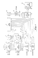
- Figure 1 shows origin vector destination address circuitry 13, drawn vector destination address circuitry 15, and source logic circuitry 55.
- the source logic circuitry 55 produces pixel addresses for reading rasterop data from the source portion of the image memory while the drawn and origin vector destination address circuits 15 and 33 produce pixel addresses for writing the data into the destination portion of image memory.
- the source and destination pixel addresses are sent to address collection circuits 57 where they are buffered, combined with refresh addresses, and multiplexed for rows and columns for writing into the bit map memory 63 through address circuit 59.
- address collection circuits 57 For the sake of simplicity, we will consider only a one-plane memory and pixel values equal to either "1" or "0".
- the source addresses provide a basis for reading pixel values so that when the destination addresses are generated, the pixel values from the "addressed" source locations will be transferred internally in the bit map memory 63 to the destination addresses generated.
- the user can choose the values used for the origin vector and the values used for the drawn vectors.
- For each vector there is an X extent DX and a Y extent DY.
- the major axis is defined as the axis which has the largest extent, in other words if
- the X axis is the major axis and the Y axis is the minor axis.
- the user chooses the major and minor axes by deciding the values of SDX, SDY, FDX and FDY (shown in Figure 2). The user also decides how the image at the destination is going to be drawn by deciding on the arithmetic signs to be designated with DX and DY.
- vector 17 to be drawn is defined by two vectorial components FDX and FDY. If the horizontal direction to the right of point 19 and the vertical direction upwards of line 21 are considered positive, then the vectorial components FDX and FDY in Figure 2 are both positive. The user enters the FDX and FDY values as positive values into the circuitry 15 of Figure 1.
- the vector 23, defined by vectorial components SDX and SDY has been chosen as the origin vector. Since SDX is directed to the left of point 19, it has a negative value while the component SDY has a positive arithmetic sign. SDX and SDY are entered into circuitry 13 of Figure 1 with the proper arithmetic signs. In the destination address circuitry 13 and 15, the absolute value of DX (i.e.
- SDX or FDX is subtracted from the absolute value of DY (i.e. SDY or FDY) and the results thereof, together with the arithmetic values of DX and DY, indicate in which octant the respective vector lies.
- DY i.e. SDY or FDY
- the relationships of DX to DY and the signs which modify them along with their designated octants can be seen in Figure 3.
- PLAs 29 and 31 respectively serve to control switching circuits in origin and drawn vector destination address circuitry 13 and 15.
- the PLAs are part number 82S100 manufactured by Signetics Corporation.
- lines 33 and 35 respectively connect destination address circuitry 13 and 15 to the state machine 37.
- the destination address circuitry 15 will count each time the X address is incremented. When the X count reaches the value FDX, a signal indicating that vector 17 has been completely drawn will be sent on line 35 to the state machine 37.
- the state machine 37 in turn will send a signal to both PLAs 29 and 31.
- PLA 29 will set the switches in destination address circuitry 13 to increment the address values along the -DX and +DY vectorial components of vector 23.
- the PLA 31 will initialize destination address circuitry 15 to provide a starting address on origin vector 23.
- the state machine 37 in a preferred embodiment is part number 82S100 manufactured by Signetics Corporation.
- FIG. 1 there is a drawn vector scale circuit 41 and an origin vector scale circuit 43.
- the input to scale circuit 41 is a drawn vector scale factor FS on line 45 and the input to scale circuit 43 is an origin vector scale factor SS on line 47.
- the scale factors and the scale circuitry enable the present system to expand or reduce the size of an image by fractional valued multiples or by whole number multiples. Expanding the source image (i.e. upscaling) is accomplished by copying one pixel value from the source into multiple pixel locations at the destination. Downscaling is accomplished by transforming multiple pixel values from the source into one pixel value at the destination.
- the scale factor FS (which is always less than 1) is accumulated each time a drawn vector pixel address is generated.
- the scale circuit 41 is designed to send a signal on line 49 which indicates to the state machine 37 that the address of the vector being drawn should be incremented.
- the state machine 37 sends a control signal to PLA 31, which in turn causes destination address circuitry 15 to increment the address of the vector being drawn.
- scale circuitry 41 sends a signal on line 51 which causes the state machine 37 to send a signal to PLA 53.
- PLA 53 in response sends a signal to the source logic circuit 55.
- the source logic circuit 55 causes the source address to be incremented.
- the system in expanding an image, the system must copy the pixel values of one source address into multiple destination addresses. In reducing an image the system must read a number of pixel values from the source image before it produces a pixel value at a single destination address.
- the system handles that assignment by producing three pixel values in the expanded image from the first pixel value in the source; two more pixel values in the expanded image from the second source pixel value; three more pixel values in the expanded image from the third source pixel value; and two more pixel values in the expanded image from the last source pixel value.
- the scale circuits 41 and 43 are designed to accomplish the foregoing averaging of pixel value generation in the expanded image.
- the address collection logic 57 and the bit map memory 63 do not represent circuitry which is part of the present invention but are shown as one example of a utility means for using the signals generated by the present invention.
- Figure 1 shows two input lines 65 and 67 connected to the destination address circuit 13.
- the values X1 and Y1 on lines 67 and 65 are respectively the X and Y addresses for the starting point, in the destination section of memory, of the transformed image.
- the SX and SY values during an initialization procedure are transferred from circuit 13 to circuit 15. Accordingly, after an initialization and the system has begun to transform an image, the starting point for each drawn vector is the address of the last-generated pixel value of the origin vector.
- the addresses FX and FY sent to the bit map memory come only from the drawn vector destination address circuit 15. It follows that the transformed image is expanded by changing the FX and FY values.
- the origin vector is advanced and therefore drawn by changing the initialization address in response to a control signal from the state machine 37.
- the scale circuits 41 and 43 receive control signals (on lines 69 and 71) from state machine 37 to initialize these circuits.
- the state machine 37 and the PLAs 29 and 31 are programmable devices and are programmed to accomplish the steps set out in this
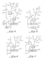
- Figures 4-7 represent a set of circuits found in the drawn vector destination address circuitry 15.
- Figures 8-11 represent a set of circuits found in the origin vector destination address circuitry 13.
- Figure 11 shows the circuit that produces the SX address, which SX address becomes the input to line 7-3 of Figure 7.
- the circuits shown in Figures 4-11 are shown in logic form, i.e. as switches, add-subtract devices, accumulators, registers and the like. Actually these circuits are made up of a plurality of integrated circuit chips in which the switching is accomplished electronically.
- the switches for all of the circuits of Figures 4-13, as well as the switches of circuit 55 of Figure 1 are multiplexers and are part number 74153 manufactured by Texas Instruments Corporation.
- the add-subtract devices for all of the circuits of Figures 4-13, as well as the add-subtract device in circuit 55 of Figure 1 are part number 74181 manufactured by Texas Instruments Corporation.
- the accumulators for all the circuits of Figures 4-13, as well as the accumulator in circuit 55 of Figure 1 are part number 7491 manufactured by Texas Instruments Corporation.
- Other types of add-subtract devices as well as other types of accumulators could be used.
- the registers, such as register 8-13, are part number 7474 manufactured by Texas Instruments Corporation.
- PLA29 (in response to signals from state machine 37) sets the switch 11-1 to the "0" position 11-2.
- the switch 11-3 is set to the "0" position 11-4. Accordingly, zero is added to zero in the add-subtract (A-S) device 11-5 and the sum of zero is placed in the accumulator 11-6.
- A-S add-subtract
- PLA 29 sets switch 11-3 to the X1 input line 11-7. The switch 11-1 remains in the "0" position, i.e., connected to line 11-2.
- the X1 address is added to zero in the add-subtract device 11-5 and the sum (i.e. X1) is transferred to accumulator 11-6.
- the value in the accumulator 11-6 is present on terminal 11-8 as the SX address, which is output to the drawn vector destination address circuitry 15.
- circuitry of Figure 10 is identical to that of the circuitry of Figure 11 except that the input is the Y1 address of the starting point of the image to be transferred as found on line 10-7.
- the circuits of Figures 6 and 7 accept the respective input signals SY and SX, which represent the starting address for a corresponding vector to be drawn, from the circuits of Figures 10 and 11.
- the address values SY and SX are respectively added to zero in A-S devices 6-5 and 7-5 by setting switch 6-1 to the "0" line 6-2 and switch 6-3 to the SY line 6-7 and by setting switch 7-1 to the "0" line 7-2 and switch 7-3 to the SX line 7-7.
- the values SY and SX are respectively stored in accumulators 6-6 and 7-6.
- PLA 31 sets switch 7-3 ( Figure 7) to the "1" input line 7-12 and sets switch 7-1 to the accumulator input line 7-13. Each time there is an output signal on line 49, PLA 31 clocks the A-S device 7-5. With switches 7-3 and 7-1 set in the aforementioned manner, the sum in the accumulator 7-6 (i.e.
- FX which initially is the last SX address
- FX is added to unity and thus there is a new address for a new pixel value to be computed for the vector being drawn.
- the FY value remains constant.
- PLA 31 has set switch 6-1 to the accumulator input line 6-13 and set switch 6-3 to the "0" input line 6-4. With such switch settings, zero is added to the original Y value from the accumulator and FY remains constant.
- switches 10-3 and 11-3 are set (in response to signals from PLA 19) to the zero position, i.e., respectively to lines 10-4 and 11-4, and switches 10-1 and 11-1 are set respectively to their accumulator input lines 10-13 and 11-13. Therefore, the SY and SX addresses are the starting Y1 and X1 addresses.
- switch 5-1 is set to the accumulator input line 5-10.
- -FDX from the accumulator is added (in the add-subtract device 5-6) to +1.
- the arithmetic sign of the accumulator contents stays negative, it provides a negative arithmetic sign value in the register 5-8.
- the accumulator contents become less negative and will eventually reach zero. The value of zero is sensed as a sign change in register 5-8.
- An arithmetic sign change in register 5-8 generates a signal at terminal 5-9 and that signal is present on line 35 of Figure 1.
- the count signal on line 35 of Figure 1 is transmitted to state machine 37, which responds by sending signals to both PLA 29 and PLA 31 as described earlier.
- state machine 37 responds by sending signals to both PLA 29 and PLA 31 as described earlier.
- "1" will be added to the Y1 address in Figure 10 and the second vector to be drawn will start at a position above the first drawn vector in the X-Y plane, i.e., (X1, Y1 + 1).
- PLA 29 sets switch 10-1 to the accumulator input line 10-13 and sets switch 10-3 to the "1" input line 10-12.
- the PLA signal clocks the "1" to be added to the initial SY address (i.e. Y1), so that the second drawn vector is started from a new address Y1 + 1.
- SX remains equal to X1 since in our example we are transforming a rectangular image without rotation.
- the circuitry of Figure 9 will count the Y address increments. Each time a pixel address is computed to further define the origin vector, the count circuit of Figure 9 increases its accumulator value by +1.
- the accumulator 9-7 is initially loaded with a -SDY value in the same way that accumulator 5-7 of Figure 5 was loaded with a -FDX value.
- a predetermined signal is generated on terminal 9-9, which is transmitted on line 33 of Figure 1.
- the end of the origin vector is reached, then only one more drawn vector is needed to complete transformation of the source image, and that message is communicated by sending the signal on line 33.
- the scale circuit of Figure 12 employs a scale factor FS of 1/2.4 or .417
- the scale circuit of Figure 13 employs a scale factor SS of 1/3.2 or .312.
- the state machine 37 transmits signals on line 69 to set switch 12-1 to the "0" input line 12-2.
- switch 12-3 is set to the "0" input line 12-4. Therefore, a zero value is added to a zero value to provide a sum of zero in accumulator 12-6, thereby resetting the scale circuit 41 to zero.
- the scale circuit 43 of Figure 13 is reset to zero in the same way.
- switch 12-3 is set to the scale factor FS line 12-9.
- a signal value .417 is transmitted from line 12-9 to A-S device 12-5.
- switch 12-1 is set to the accumulator input line 12-8.
- a pixel address is computed for the drawn vector, in response to a signal on line 49 and a clock signal in state machine 37.
- the signal on line 49 is generated for the entire time if the system is upscaling.
- Flip-flop 50 is set, i.e. switched to its Q side, if the system is operating in an upscaling mode.
- the overflow signal will pass through the OR gate 65 to provide an increment control signal on line 51.
- the overflow signal is output in response to the contents of accumulator 12-6 exceeding a whole number (i.e. an integer). If the system is doing a downscale, then flip-flop 50 is set to the side and there is a constant increment control signal on line 51. Bear in mind that the drawn vector will be completed before the system increments the origin vector address.
- the value .417 from the accumulator 12-6 is added to .417 from the scale factor FS line 12-9 and the value of .834 is stored in the accumulator.
- a second pixel address has been computed for the expanded vector being drawn.
- the value .834 from the accumulator 12-6 is added to .417 from the scale factor FS line 12-9 and hence the accumulator should have the sum 1.251 stored therein.
- the accumulator 12-6 is designed to treat the value of "1" as a carry and thus provide a signal on line 12-11.
- the carry signal on line 12-11 causes the overflow circuit 12-7 to provide a signal on line 51 through the OR gate 65.
- Table I shows that for the first, third, sixth and eighth source pixel addresses there were three drawn vector pixel addresses computed and for each of the other source pixel addresses only two drawn vector pixel addresses were computed.
- Each of the 13 drawn vectors would follow the same pattern in the X direction. However, the pattern in the Y direction would differ due to the different scale factor.
- the circuitry of Figure 13 operates in the same fashion as the circuitry of Figure 12 except that switch 13-3 is only set to the scale factor SS line 13-9 in response to a count signal on line 35 of Figure 1.
- the Bresenham algorithm circuit of the drawn vector destination address circuit is shown in Figure 4. This circuit enables the image to be rotated. Bresenham's algorithm provides a technique, or a routine, by which an arbitrary vector can be approximated on a rectangular grid of pixels. (The Bresenham algorithm is used by the transformation circuit arrangement of the invention, but was not invented by the Applicants.) In order to select those pixels corresponding to the rotated vector, some pixels are located diagonally from the previously generated pixels. If the address of a pixel value locates that pixel value at a position diagonal to the location of the last pixel value, then both the major axis and minor axis addresses are incremented.
- Bresenham's algorithm provides a basis for determining whether both the major and minor axes addresses or only the major axis address should be incremented.
- Figure 14 shows an image S (for source) located in the source portion of the memory and an image D (for destination) located in the destination portion of the memory.
- the image D has been rotated.
- the user decides to what angle the destination image should be rotated and chooses FDY and SDX to effect the proper angular rotation.
- FDY has a value of 5 pixels
- SDX has a value of 2 pixels. If Bresenham's algorithm is changed slightly so that the end strokes along the major axis are divided, a better average of the pixel values along the intended diagonal line as it appears to the viewer is obtained.
- the absolute value of the vectorial component along the major axis is subtracted from the absolute value of the vectorial component along the minor axis. If the difference is negative, only the major axis address is incremented whereas if the difference is positive, both the major and minor axes addresses are incremented. Further, if the difference is negative, then in the following step the difference value is added to the absolute value of the component along the minor axis. Table II sets forth the Bresenham algorithm and the manner in which it is applied through the destination address circuitry 13 and 15.
- step 2 of Table II states that only the X address should be incremented. Accordingly, pixel 79 is located one pixel position to the right.
- the pixels in Figure 14 are grouped along the desired position of the vector 73 to be drawn and the viewer sees these pixels as a line approximating vector 73.
- FIG. 8 is the Bresenham algorithm circuit found in the origin vector destination address circuit 13.
- switches 8-1, 8-3 and 8-5 are respectively set to the "0" input lines 8-2, 8-4 and 8-6. Hence all of the zeros are added together and the Bresenham circuit of Figure 8 is reset to zero.
- switch 8-3 is set to line 8-7 while switch 8-1 remains set at "0" input line 8-2.
- switch 8-5 is set to the SDY line 8-9 and SDX is transferred from the A-S device 8-8 to be subtracted from SDY in the A-S device 8-10.
- the difference computed in A-S device 8-10 is stored in the accumulator 8-11. If the difference in the accumulator 8-11 is negative, then SDX is the component along the major axis; if the difference is positive, then SDY is the component along the major axis.
- the arithmetic sign bit from the difference is stored in flip-flop 8-12, and that signal is one of the three signals sent on lines 25 to PLA 29.
- the two other signals on lines 25, which indicate the sign values of SDX and SDY, are stored in two flip-flops (not shown) which receive their arithmetic sign input directly from the input signals on lines 26 in Figure 1.
- the circuitry of Figure 4 is initialized in the same fashion as the circuitry of Figure 8.
- a zero is interpreted as an arithmetic plus sign, which sign is stored in register 4-13.
- Register 4-13 in a preferred embodiment is a 74S74 manufactured by Texas Instruments Corporation.
- the arithmetic sign signal from register 4-13 is transmitted on line 28 to PLA 31.
- PLA 31 responds to the plus sign signal to set the switches 7-3 and 6-3 to their respective "1" input lines and hence both the FX and FY addresses are incremented as indicated in the last two columns of Table II. Accordingly pixel 77 of Figure 14 is located as shown.
- PLA 31 will set switch 4-3 at its FDX input on line 4-7 while switch 4-1 remains set at line 4-14 and switch 4-5 remains set at FDY input line 4-9.
- the accumulator 4-11 provides a zero to the A-S device 4-8, while line 4-7 provides FDX to the A-S device 4-8 and the control signal from PLA 31 causes
- the -FDX value is transferred to the A-S device 4-10, whereat
- PLA 31 responds to the arithmetic negative sign to set switch 6-3 at the "0" input line 6-4 while switch 7-3 remains set at the "1" input line 7-12. Accordingly only the FX address is incremented, as indicated in the last two columns of Table II. It follows that pixel 79 of Figure 14 is located as shown. The system continues the operation of generating signals for PLA 31, which in turn directs the circuitry of Figures 6 and 7 to generate the proper FX and FY signals.
- the Bresenham algorithm circuitry of Figure 8 operates in an identical fashion, providing signals to PLA 29 (line 30 being analogous to line 28), which in turn directs the address circuits of Figures 10 and 11 to generate SX and SY addresses.
- the addresses to provide pixels along origin vector 74 in Figure 14 are only incremented when the count circuit of Figure 5 indicates that a drawn vector has been completely drawn.
- the count circuit of Figure 5 operates to count, in response to control signals from PLA 31 (as described earlier), each time a pixel value, such as pixels 77 and 79, is generated.
- FIG 15 there is shown a vector 81 which has the same slope as vector 73 in Figure 14 but which is twice as long. Letters have been placed at positions corresponding to the centers of pixels and of course the pixel positions of Figure 15 would be twice as large as the pixel positions of Figure 14.
- Figure 15 is exaggerated to show the arrangement by which holes occur.
- "A”s depict the centers of pixels forming a vector along line 81.
- "B”s depict centers of pixels forming a second vector along line 83. Positions 85, 87, 89, 91 and 93 have neither an A nor a B and therefore are deemed to be holes.
- the system first examines the arithmetic signs of SDX, SDY, FDX and FDY. If there is an odd number of minus signs, then holes are possible. In addition, holes will occur only during the generation of pixel addresses which form the drawn vectors when the origin of one drawn vector is diagonally displaced along the origin vector relative to the origin of the next drawn vector. Finally, holes occur when the above two conditions are present and the address of a subsequent pixel on a drawn vector is located diagonally with respect to the address of a previously generated pixel. The first condition is detected in the state machine 37 and the second and third conditions are detected by the Bresenham algorithm circuits, which output appropriate signals to the state machine.
- a plus sign signal along line 28 from the Bresenham algorithm circuitry of Figure 4 would indicate that the address of a subsequent pixel on a drawn vector will be located diagonally with respect to a previously generated pixel address, which is the third condition mentioned above to alert the system to a hole fill.
- the sign signal from the circuitry of Figure 4 is output to the hole test AND gate in the state machine 37. It is apparent from a consideration of Figure 15 that all three conditions are present for generating holes during generation of the A pixels. There are no holes generated when the B pixels are computed, since the second condition, i.e. that the origin of the next drawn vector be located diagonally with respect to the previous drawn vector origin, is not present. The origin 97 of vector C is not located diagonally with respect to the origin 99 of vector B.
- state machine 37 sends an instruction signal to PLA 31 which in turn enables the circuitry of Figures 5-7.
- the instruction signal from PLA 31 sets switch 7-3 to "0" input line 7-4 and sets switch 6-3 to its "1" input line 6-12 so that only the Y axis address will be incremented.
- switch 5-4 is set to the "0" input line 5-11 so that the pixel value added at location 85 will not be counted.
- the switches 4-1, 4-3 and 4-5 of the Bresenham algorithm circuit in Figure 4 will be set to their "0" inputs to prevent a new instruction during the time frame in which the pixel value in location 85 is generated.
- the state machine 37 instructs PLA 31 to set switch 7-3 to the "1" input line 7-12; switch 6-3 to the "0" input line 6-4; switch 5-4 to the "1” input line 5-5; and switches 4-1, 4-3 and 4-5 respectively to the accumulator input line 4-14, the FDX input line 4-7 and the FDY input line 4-9.
- the address along the X axis is incremented and the next FX address is where the A pixel value 101 is located.
- the pixel value at location 101 will be counted and the Bresenham circuit will generate new instructions for incrementing the address to generate the A pixel 103.
Abstract
Description
- In the video display art there are techniques referred to as rasterops, which is a short-hand notation for raster operations. In general the notion of rasterops is the concept of moving information, which is arranged in a pattern, from one part of memory to another part of memory while still maintaining the pattern or some version thereof. Known circuit arrangements expand or contract a pattern defined by pixel bits of information. However, such expansions and contractions have been by whole number multiples of the dimensions and not by fractional-valued multiples of the dimensions. In addition, prior art rasterops circuits have provided a means to rotate (by multiples of 90 degrees) images as viewed on a video display screen. However, if an image is rotated by some arbitrary angle different than 90 degrees, the edge lines of such a rotated image very often resemble a step function configuration and some of the pixels needed to provide a solid image are missing. The present invention is arranged to fill in these holes. In addition, the present system permits many different transformations between the source image and destination image. For instance, the present system enables the user to display a number of different font sizes while employing a single font resource.
- In this description the sequence of parallel vectors which are drawn while performing a raster operation will be referred to as "drawn" vectors. The sequence of the points of origin of these "drawn" vectors forms a vector which will be referred to as the "origin" vector. For example, in Figure 2, the
numerals 17 and 39 indicate "drawn" vectors andnumeral 23 indicates the origin vector from which the "drawn" vectors are drawn. In the case where the source image is made up of a plurality of parallel vectors extending in the X direction (i.e. the X vectors) from a vector extending in the Y direction (i.e. the Y vector), the "drawn" vectors are X vectors of the source image and the transformed (i.e. rotated and/or scaled) X vectors of the transformed image and the "origin" vectors are the Y vector of the source image and transformed Y vector of the transformed image. - The present circuit arrangement includes circuitry for generating source addresses, circuitry for generating drawn vector destination addresses, and circuitry for generating origin vector destination addresses. The source address circuitry provides a sequence of pixel addresses that define a rectangular area in the image memory. The drawn vector destination address circuitry generates a sequence of pixel addresses that trace arbitrary lines in the image memory. The origin vector destination address circuitry generates a sequence of pixel addresses that trace a line in the image memory different than the line traced by the pixel addresses from the drawn vector destination address circuitry. Each point along the origin vector is used as the origin of a drawn vector. The combination of the drawn vectors originating along an origin vector results in a sequence of pixel addresses that define an arbitrarily oriented parallelogram in the image memory. This parallelogram is a transformation of the source rectangle, i.e. each destination drawn vector is a transformation of a corresponding source drawn vector and the destination origin vector is a transformation of the source origin vector. Accordingly, the image of the source rectangle may be transformed into an arbitrary parallelogram in the image memory. In addition, the present system includes circuitry which handles scale factors for enabling the source image and transformed image to be of different sizes.
- Each of the destination address circuits includes an X address circuit, a Y address circuit, a count circuit and a Bresenham algorithm circuit. The present system is employed with circuitry which includes a timing circuit that generates 960-nanosecond time frames during a horizontal scan. Every other time frame is used for refreshing the screen. The remaining time frames are employed to read pixel information from a source address and to write pixel information into a destination address in a bit map memory. The X and Y address circuits provide the addresses into which such pixel information should be written. The count circuit determines when a vector which is being drawn is complete. When all of the pixel values of a drawn vector have been written, the count circuit sends a message to the system in response to which the origin vector address is incremented. The Bresenham algorithm circuits provide control signals which tell the system to increment pixel addresses along the vectorial components of the major and minor axes or to generate a sequence of pixel addresses that trace an arbitrary line in image memory. The Bresenham algorithm circuits are also employed to fill holes by interrupting what would be a normal two-increment diagonal placement of a pixel value and instead causing a one-increment address procedure with the placement of a pixel value thereat followed by a second increment address generation to the normal diagonal location. The two-step procedure will cause a hole to be filled. The origin vector destination address circuit generates a sequence of pixel addresses that trace another line in image memory. Each point along the origin vector is used as the origin for a drawn vector. The foregoing results in a sequence of pixel addresses that defines an arbitrarily oriented parallelogram in the image memory. Thus, the rectangular area of the source may be transformed into an arbitrarily configured parallelogram at another location (destination) in image memory. In addition, scale factor circuits are employed to permit the source and transformed images to be different sizes.
- The objects and features of the present invention will be described in detail with reference to the drawings wherein:
- Figure 1 is a block diagram schematic of the overall system along with a bit map memory system;
- Figure 2 depicts a parallelogram in the destination location in memory;
- Figure 3 shows the octants in which a vector can be drawn and the DX and DY conditions associated with each octant;
- Figures 4-7 show portions of the drawn vector destination address circuitry:
- Figure 4 is a logic circuit which implements Bresenham's algorithm for use in generating drawn vector destination addresses;
- Figure 5 is a logic circuit which counts the pixel addresses which are incremented to determine when a drawn vector has been completely drawn;
- Figure 6 is a logic circuit which generates drawn vector Y address components;
- Figure 7 is a logic circuit which generates drawn vector X address components;
- Figures 8-11 show portions of the origin vector destination address circuitry:
- Figure 8 is a logic circuit which implements Bresenham's algorithm for use in generating origin vector destination addresses;
- Figure 9 is a logic circuit which counts the pixel addresses which are incremented to determine when the last pixel of the origin vector has been generated;
- Figure 10 is a logic circuit which generates origin vector Y address components;
- Figure 11 is a logic circuit which generates origin vector X address components;
- Figure 12 is a logic circuit which forms part of the drawn vector scale circuit and which generates control signals which are used to scale an image along the drawn vector component axis;
- Figure 13 is a logic circuit which forms part of the origin vector scale circuit and which generates control signals which are used to scale an image along the origin vector component axis;
- Figure 14 depicts both a source image which has been rotated and the effect of Bresenham's algorithm; and
- Figure 15 depicts a rotated image in need of hole fill.
- Figure 1 shows origin vector destination address circuitry 13, drawn vector
destination address circuitry 15, andsource logic circuitry 55. Thesource logic circuitry 55 produces pixel addresses for reading rasterop data from the source portion of the image memory while the drawn and origin vectordestination address circuits 15 and 33 produce pixel addresses for writing the data into the destination portion of image memory. The source and destination pixel addresses are sent to addresscollection circuits 57 where they are buffered, combined with refresh addresses, and multiplexed for rows and columns for writing into thebit map memory 63 throughaddress circuit 59. For the sake of simplicity, we will consider only a one-plane memory and pixel values equal to either "1" or "0". The source addresses provide a basis for reading pixel values so that when the destination addresses are generated, the pixel values from the "addressed" source locations will be transferred internally in thebit map memory 63 to the destination addresses generated. - The user can choose the values used for the origin vector and the values used for the drawn vectors. For each vector, there is an X extent DX and a Y extent DY. The major axis is defined as the axis which has the largest extent, in other words if |DX| > |DY|, then X is the major axis. For purposes of this discussion, we will assume that the X axis is the major axis and the Y axis is the minor axis. The user chooses the major and minor axes by deciding the values of SDX, SDY, FDX and FDY (shown in Figure 2). The user also decides how the image at the destination is going to be drawn by deciding on the arithmetic signs to be designated with DX and DY.
- In Figure 2 vector 17 to be drawn is defined by two vectorial components FDX and FDY. If the horizontal direction to the right of
point 19 and the vertical direction upwards ofline 21 are considered positive, then the vectorial components FDX and FDY in Figure 2 are both positive. The user enters the FDX and FDY values as positive values into thecircuitry 15 of Figure 1. In Figure 2, thevector 23, defined by vectorial components SDX and SDY, has been chosen as the origin vector. Since SDX is directed to the left ofpoint 19, it has a negative value while the component SDY has a positive arithmetic sign. SDX and SDY are entered into circuitry 13 of Figure 1 with the proper arithmetic signs. In thedestination address circuitry 13 and 15, the absolute value of DX (i.e. SDX or FDX) is subtracted from the absolute value of DY (i.e. SDY or FDY) and the results thereof, together with the arithmetic values of DX and DY, indicate in which octant the respective vector lies. The relationships of DX to DY and the signs which modify them along with their designated octants can be seen in Figure 3. - As can be seen from Figure 3, if three parameters are known, then the octant position of the vector is known. If the arithmetic sign of DX, the arithmetic sign of DY and the larger of DX or DY is known, then the system knows in which octant the vector lies. As previously mentioned, the user (the program) provides the arithmetic signs and magnitudes of DX and DY. Signals representing the three parameters are transmitted on
lines PLAs 29 and 31 respectively serve to control switching circuits in origin and drawn vectordestination address circuitry 13 and 15. In a preferred embodiment the PLAs are part number 82S100 manufactured by Signetics Corporation. - It can also be seen in Figure 1 that lines 33 and 35 respectively connect
destination address circuitry 13 and 15 to thestate machine 37. When a vector is being drawn, thedestination address circuitry 15 will count each time the X address is incremented. When the X count reaches the value FDX, a signal indicating that vector 17 has been completely drawn will be sent online 35 to thestate machine 37. Thestate machine 37 in turn will send a signal to bothPLAs 29 and 31. In response to this signal fromstate machine 37,PLA 29 will set the switches in destination address circuitry 13 to increment the address values along the -DX and +DY vectorial components ofvector 23. In addition, the PLA 31 will initializedestination address circuitry 15 to provide a starting address onorigin vector 23. By incrementing the component addresses oforigin vector 23 and initializing the X and Y addresses to start at the incremented addresses oforigin vector 23, asecond vector 39 is started and ultimately drawn. Thestate machine 37 in a preferred embodiment is part number 82S100 manufactured by Signetics Corporation. - As can be further seen in Figure 1, there is a drawn vector scale circuit 41 and an origin vector scale circuit 43. The input to scale circuit 41 is a drawn vector scale factor FS on line 45 and the input to scale circuit 43 is an origin vector scale factor SS on
line 47. The scale factors and the scale circuitry enable the present system to expand or reduce the size of an image by fractional valued multiples or by whole number multiples. Expanding the source image (i.e. upscaling) is accomplished by copying one pixel value from the source into multiple pixel locations at the destination. Downscaling is accomplished by transforming multiple pixel values from the source into one pixel value at the destination. - For instance, for upscaling, in drawn vector scale circuit 41 the scale factor FS (which is always less than 1) is accumulated each time a drawn vector pixel address is generated. The scale circuit 41 is designed to send a signal on
line 49 which indicates to thestate machine 37 that the address of the vector being drawn should be incremented. Thestate machine 37 sends a control signal to PLA 31, which in turn causesdestination address circuitry 15 to increment the address of the vector being drawn. When the sum of the scale factors exceeds 1, then scale circuitry 41 sends a signal online 51 which causes thestate machine 37 to send a signal toPLA 53.PLA 53 in response sends a signal to thesource logic circuit 55. Thesource logic circuit 55 causes the source address to be incremented. As mentioned above, in expanding an image, the system must copy the pixel values of one source address into multiple destination addresses. In reducing an image the system must read a number of pixel values from the source image before it produces a pixel value at a single destination address. By way of example, if an image in the source had a vector four units long and the program called for expanding it by a factor of 2.5, then the resulting vector would be ten units long. The system handles that assignment by producing three pixel values in the expanded image from the first pixel value in the source; two more pixel values in the expanded image from the second source pixel value; three more pixel values in the expanded image from the third source pixel value; and two more pixel values in the expanded image from the last source pixel value. Hence there would be ten pixel values in the expanded image for the four pixel values in the source. The scale circuits 41 and 43 are designed to accomplish the foregoing averaging of pixel value generation in the expanded image. - The
address collection logic 57 and thebit map memory 63 do not represent circuitry which is part of the present invention but are shown as one example of a utility means for using the signals generated by the present invention. - Figure 1 shows two
input lines lines circuit 15. Accordingly, after an initialization and the system has begun to transform an image, the starting point for each drawn vector is the address of the last-generated pixel value of the origin vector. Note that the addresses FX and FY sent to the bit map memory come only from the drawn vectordestination address circuit 15. It follows that the transformed image is expanded by changing the FX and FY values. The origin vector is advanced and therefore drawn by changing the initialization address in response to a control signal from thestate machine 37. The scale circuits 41 and 43 receive control signals (onlines 69 and 71) fromstate machine 37 to initialize these circuits. Thestate machine 37 and thePLAs 29 and 31 are programmable devices and are programmed to accomplish the steps set out in this description. - Figures 4-7 represent a set of circuits found in the drawn vector
destination address circuitry 15. Figures 8-11 represent a set of circuits found in the origin vector destination address circuitry 13. Figure 11 shows the circuit that produces the SX address, which SX address becomes the input to line 7-3 of Figure 7. The circuits shown in Figures 4-11 are shown in logic form, i.e. as switches, add-subtract devices, accumulators, registers and the like. Actually these circuits are made up of a plurality of integrated circuit chips in which the switching is accomplished electronically. In a preferred embodiment the switches for all of the circuits of Figures 4-13, as well as the switches ofcircuit 55 of Figure 1, are multiplexers and are part number 74153 manufactured by Texas Instruments Corporation. Other types of switching means and other forms of multiplexers could be used. In a preferred embodiment the add-subtract devices for all of the circuits of Figures 4-13, as well as the add-subtract device incircuit 55 of Figure 1, are part number 74181 manufactured by Texas Instruments Corporation. In a preferred embodiment, the accumulators for all the circuits of Figures 4-13, as well as the accumulator incircuit 55 of Figure 1, are part number 7491 manufactured by Texas Instruments Corporation. Other types of add-subtract devices as well as other types of accumulators could be used. The registers, such as register 8-13, are part number 7474 manufactured by Texas Instruments Corporation. - During initialization, PLA29 (in response to signals from state machine 37) sets the switch 11-1 to the "0" position 11-2. In addition, the switch 11-3 is set to the "0" position 11-4. Accordingly, zero is added to zero in the add-subtract (A-S) device 11-5 and the sum of zero is placed in the accumulator 11-6. It follows that the SX address circuit of Figure 11 is initially reset to zero. The circuits of Figures 4-10 are operated for reset in a similar manner and thus all of these circuits are reset to zero. In the next step during initialization,
PLA 29 sets switch 11-3 to the X₁ input line 11-7. The switch 11-1 remains in the "0" position, i.e., connected to line 11-2. During the proper clock time the X₁ address is added to zero in the add-subtract device 11-5 and the sum (i.e. X₁) is transferred to accumulator 11-6. The value in the accumulator 11-6 is present on terminal 11-8 as the SX address, which is output to the drawn vectordestination address circuitry 15. - The operation of the circuitry of Figure 10 is identical to that of the circuitry of Figure 11 except that the input is the Y₁ address of the starting point of the image to be transferred as found on line 10-7.
- The circuits of Figures 6 and 7 accept the respective input signals SY and SX, which represent the starting address for a corresponding vector to be drawn, from the circuits of Figures 10 and 11. The address values SY and SX are respectively added to zero in A-S devices 6-5 and 7-5 by setting switch 6-1 to the "0" line 6-2 and switch 6-3 to the SY line 6-7 and by setting switch 7-1 to the "0" line 7-2 and switch 7-3 to the SX line 7-7. The values SY and SX are respectively stored in accumulators 6-6 and 7-6. Hence the initial address values of FY and FX are respectively set equal to SY and SX, which are in turn respectively equal to Y₁ and X₁. Since both the first drawn vector and the origin vector start at the same X-Y address when being transferred to bit map memory (i.e. the starting point chosen by the user), it follows that initially X₁ = SX = FX and Y₁ = SY = FY.
- If we assume, by way of example, that the image to be moved has a rectangular boundary (defined along the X and Y directions), that there is to be no rotation and that the drawn vectors will extend in the X direction, then only Figures 7 and 10 need to be discussed, since the drawn vectors will have no Y component. Under such circumstances, PLA 31 sets switch 7-3 (Figure 7) to the "1" input line 7-12 and sets switch 7-1 to the accumulator input line 7-13. Each time there is an output signal on
line 49, PLA 31 clocks the A-S device 7-5. With switches 7-3 and 7-1 set in the aforementioned manner, the sum in the accumulator 7-6 (i.e. FX, which initially is the last SX address) is added to unity and thus there is a new address for a new pixel value to be computed for the vector being drawn. During each read and write time frame, the FY value remains constant. The foregoing is true because PLA 31 has set switch 6-1 to the accumulator input line 6-13 and set switch 6-3 to the "0" input line 6-4. With such switch settings, zero is added to the original Y value from the accumulator and FY remains constant. During drawing of the first vector on the video display, both switches 10-3 and 11-3 are set (in response to signals from PLA 19) to the zero position, i.e., respectively to lines 10-4 and 11-4, and switches 10-1 and 11-1 are set respectively to their accumulator input lines 10-13 and 11-13. Therefore, the SY and SX addresses are the starting Y₁ and X₁ addresses. - As pixel addresses are computed for the vector being drawn, the addresses are counted in the count circuit of Figure 5, which is initially reset to zero. Thereafter, during further initialization, switch 5-4 is set to line 5-3 to receive the FDX value, while switch 5-1 is set to line 5-2 to receive the zero reset value. FDX is provided by the user. However, when FDX is passed to A-S device 5-6, it is subtracted from zero and hence the sum -FDX is stored in accumulator 5-7. The arithmetic sign of the sum is directed to the register 5-8. When pixel addresses are being computed for the vector being drawn, switch 5-4 is set (by PLA 31) to the "1" terminal 5-5. At the same time switch 5-1 is set to the accumulator input line 5-10. At the time that the first pixel address is computed, -FDX from the accumulator is added (in the add-subtract device 5-6) to +1. As long as the arithmetic sign of the accumulator contents stays negative, it provides a negative arithmetic sign value in the register 5-8. As "1"s are added to -FDX, the accumulator contents become less negative and will eventually reach zero. The value of zero is sensed as a sign change in register 5-8. An arithmetic sign change in register 5-8 generates a signal at terminal 5-9 and that signal is present on
line 35 of Figure 1. - The count signal on
line 35 of Figure 1 is transmitted tostate machine 37, which responds by sending signals to bothPLA 29 and PLA 31 as described earlier. In response to the signal fromPLA 29 and assuming that the ground rules of Figure 3 are in effect (i.e. the positive Y direction is up), "1" will be added to the Y₁ address in Figure 10 and the second vector to be drawn will start at a position above the first drawn vector in the X-Y plane, i.e., (X₁, Y₁ + 1). - Under these
circumstances PLA 29 sets switch 10-1 to the accumulator input line 10-13 and sets switch 10-3 to the "1" input line 10-12. The PLA signal clocks the "1" to be added to the initial SY address (i.e. Y₁), so that the second drawn vector is started from a newaddress Y₁ + 1. SX remains equal to X₁ since in our example we are transforming a rectangular image without rotation. At the same time the circuitry of Figure 9 will count the Y address increments. Each time a pixel address is computed to further define the origin vector, the count circuit of Figure 9 increases its accumulator value by +1. The accumulator 9-7 is initially loaded with a -SDY value in the same way that accumulator 5-7 of Figure 5 was loaded with a -FDX value. When the value in accumulator 9-7 is increased to zero, an arithmetic sign change is detected and a predetermined signal is generated on terminal 9-9, which is transmitted on line 33 of Figure 1. When the end of the origin vector is reached, then only one more drawn vector is needed to complete transformation of the source image, and that message is communicated by sending the signal on line 33. - Note from Figure 1 that when the SOX and SOY addresses are generated from the
source logic 55, they are transmitted to theaddress collection logic 57 as mentioned earlier. The addresses SOX and SOY are not incremented until the scale circuits generate signals onlines - Referring to Figure 12, during initialization the
state machine 37 transmits signals online 69 to set switch 12-1 to the "0" input line 12-2. In addition, switch 12-3 is set to the "0" input line 12-4. Therefore, a zero value is added to a zero value to provide a sum of zero in accumulator 12-6, thereby resetting the scale circuit 41 to zero. The scale circuit 43 of Figure 13 is reset to zero in the same way. After initialization, switch 12-3 is set to the scale factor FS line 12-9. A signal value .417 is transmitted from line 12-9 to A-S device 12-5. At the same time, switch 12-1 is set to the accumulator input line 12-8. In response to a clock signal at A-S device 12-5, the value .417 is added to 0 and stored in accumulator 12-6. Coincident with the addition of the factor .417, a pixel address is computed for the drawn vector, in response to a signal online 49 and a clock signal instate machine 37. The signal online 49 is generated for the entire time if the system is upscaling. Flip-flop 50 is set, i.e. switched to its Q side, if the system is operating in an upscaling mode. The overflow signal will pass through theOR gate 65 to provide an increment control signal online 51. The overflow signal is output in response to the contents of accumulator 12-6 exceeding a whole number (i.e. an integer). If the system is doing a downscale, then flip-flop 50 is set to theside and there is a constant increment control signal on
line 51. Bear in mind that the drawn vector will be completed before the system increments the origin vector address. - During the next clock time the value .417 from the accumulator 12-6 is added to .417 from the scale factor FS line 12-9 and the value of .834 is stored in the accumulator. In the meantime a second pixel address has been computed for the expanded vector being drawn. During the next clock time the value .834 from the accumulator 12-6 is added to .417 from the scale factor FS line 12-9 and hence the accumulator should have the sum 1.251 stored therein. However, the accumulator 12-6 is designed to treat the value of "1" as a carry and thus provide a signal on line 12-11. The carry signal on line 12-11 causes the overflow circuit 12-7 to provide a signal on
line 51 through theOR gate 65. It follows then that the source address SOX is incremented by "1" and there is a value of .251 remaining in the accumulator. Thus, for the first pixel address in the source section of memory three pixel addresses have been computed for the vector being drawn. Table 1 shows the relationship between the pixel values in the source vector and the pixel values in the drawn vector. It should be recognized that FDX of the destination image will be 24 pixels because the 10 pixels in the X direction of the source image are being expanded by a factor of 2.4.
- Table I shows that for the first, third, sixth and eighth source pixel addresses there were three drawn vector pixel addresses computed and for each of the other source pixel addresses only two drawn vector pixel addresses were computed. Each of the 13 drawn vectors would follow the same pattern in the X direction. However, the pattern in the Y direction would differ due to the different scale factor. The circuitry of Figure 13 operates in the same fashion as the circuitry of Figure 12 except that switch 13-3 is only set to the scale factor SS line 13-9 in response to a count signal on
line 35 of Figure 1. - The Bresenham algorithm circuit of the drawn vector destination address circuit is shown in Figure 4. This circuit enables the image to be rotated. Bresenham's algorithm provides a technique, or a routine, by which an arbitrary vector can be approximated on a rectangular grid of pixels. (The Bresenham algorithm is used by the transformation circuit arrangement of the invention, but was not invented by the Applicants.) In order to select those pixels corresponding to the rotated vector, some pixels are located diagonally from the previously generated pixels. If the address of a pixel value locates that pixel value at a position diagonal to the location of the last pixel value, then both the major axis and minor axis addresses are incremented. If the address of a pixel value should locate that pixel value at a pixel position along the major axis displaced from the last pixel value, then only the major axis address is incremented. Bresenham's algorithm provides a basis for determining whether both the major and minor axes addresses or only the major axis address should be incremented.
- Figure 14 shows an image S (for source) located in the source portion of the memory and an image D (for destination) located in the destination portion of the memory. The image D has been rotated. The user decides to what angle the destination image should be rotated and chooses FDY and SDX to effect the proper angular rotation. Using the rectangle discussed in our previous example (10 pixels by 4 pixels), we choose an angle of rotation of 30°. Hence FDY has a value of 5 pixels and SDX has a value of 2 pixels. If Bresenham's algorithm is changed slightly so that the end strokes along the major axis are divided, a better average of the pixel values along the intended diagonal line as it appears to the viewer is obtained. According to Bresenham's algorithm, in order to generate addresses for a vector, the absolute value of the vectorial component along the major axis is subtracted from the absolute value of the vectorial component along the minor axis. If the difference is negative, only the major axis address is incremented whereas if the difference is positive, both the major and minor axes addresses are incremented. Further, if the difference is negative, then in the following step the difference value is added to the absolute value of the component along the minor axis. Table II sets forth the Bresenham algorithm and the manner in which it is applied through the
destination address circuitry 13 and 15.
- In Table II each time the accumulator had a difference of zero (or if there had been a plus answer), both the X and Y addresses of the vector being drawn were incremented and each time the accumulator had a negative value therein, only the X address was incremented. In Figure 14 the pixels are shown in the locations directed by Table II. The pixels in Figure 14 are drawn smaller than their actual size as related to the drawing (since we assumed that the image size was 10 pixels by 4 pixels) in order to make the drawing more meaningful. The starting point of vector 73 is the
point 75. Note thatstep 1 of Table II states that both the X and Y addresses should be incremented and hencepixel 77 is located one pixel position to the right and one pixel position above. Note thatstep 2 of Table II states that only the X address should be incremented. Accordingly,pixel 79 is located one pixel position to the right. By following the arithmetic sign interpretation of Table II, it can be seen that the pixels in Figure 14 are grouped along the desired position of the vector 73 to be drawn and the viewer sees these pixels as a line approximating vector 73. - Consider now the operation of the Bresenham algorithm circuitry shown in Figures 4 and 8. The system must first decide what the major and minor axes are for the drawn and origin vectors and in what octant the vectors are going to be located. The user knows where the transformed image is to be drawn and, in accordance with the octant relationships shown in Figure 3, provides signs for the component axes. The user also knows how much the image is to be rotated and therefore the user deterimines the values of FDX, FDY, SDX and SDY. While it would be a simple matter for the user to provide the information as to which axis would be the major axis, the system uses the Bresenham algorithm circuit to make that determination.
- Consider Figure 8 which is the Bresenham algorithm circuit found in the origin vector destination address circuit 13. During initialization, switches 8-1, 8-3 and 8-5 are respectively set to the "0" input lines 8-2, 8-4 and 8-6. Hence all of the zeros are added together and the Bresenham circuit of Figure 8 is reset to zero. Thereafter, during initialization switch 8-3 is set to line 8-7 while switch 8-1 remains set at "0" input line 8-2. Thus, the SDX value is added to zero in the add-subtract device 8-8. At the same time switch 8-5 is set to the SDY line 8-9 and SDX is transferred from the A-S device 8-8 to be subtracted from SDY in the A-S device 8-10. The difference computed in A-S device 8-10 is stored in the accumulator 8-11. If the difference in the accumulator 8-11 is negative, then SDX is the component along the major axis; if the difference is positive, then SDY is the component along the major axis. The arithmetic sign bit from the difference is stored in flip-flop 8-12, and that signal is one of the three signals sent on
lines 25 toPLA 29. The two other signals onlines 25, which indicate the sign values of SDX and SDY, are stored in two flip-flops (not shown) which receive their arithmetic sign input directly from the input signals onlines 26 in Figure 1. The circuitry of Figure 4 is initialized in the same fashion as the circuitry of Figure 8. - During the initialization (as just described), the system has determined that, with respect to the drawn vector 73 (Figure 14), X is the major axis and Y is the minor axis. Prior to the first time frame for reading from the source and writing into the destination location of memory, the starting addresses for FX and FY will be generated as described earlier with respect to the circuits of Figures 6 and 7. Referring to Figure 4, during the first time frame for reading from the source and writing into the destination, switch 4-1 will be set to the accumulator input line 4-14; switch 4-3 will be set to the FDX/2 input line 4-15; and switch 4-5 will be set to the FDX input line 4-9. Since there is a zero in the accumulator from the reset procedure (described above), FDX/2 gets subtracted from zero in the A-S device 4-8, which results in a difference signal of -FDX/2. The signal from PLA 31 directs the A-S device 4-8 to subtract. The value of -FDX/2 is then directed to A-S device 4-10, where the absolute value of FDX/2 is subtracted from the absolute value of FDY (i.e. |FDY| - |FDX/2|). From the numerical values of Table II, we find that the calculations in the two A-S devices 4-8 and 4-10 result in 0 - 5 + 5 = 0. Hence there is a zero in accumulator 4-11. A zero is interpreted as an arithmetic plus sign, which sign is stored in register 4-13. Register 4-13 in a preferred embodiment is a 74S74 manufactured by Texas Instruments Corporation. The arithmetic sign signal from register 4-13 is transmitted on
line 28 to PLA 31. PLA 31 responds to the plus sign signal to set the switches 7-3 and 6-3 to their respective "1" input lines and hence both the FX and FY addresses are incremented as indicated in the last two columns of Table II. Accordinglypixel 77 of Figure 14 is located as shown. During the next time frame wherein the source is read and the destination is written into, PLA 31 will set switch 4-3 at its FDX input on line 4-7 while switch 4-1 remains set at line 4-14 and switch 4-5 remains set at FDY input line 4-9. In accordance with the settings of the switches and the last time frame operation, the accumulator 4-11 provides a zero to the A-S device 4-8, while line 4-7 provides FDX to the A-S device 4-8 and the control signal from PLA 31 causes |FDX| to be subtracted from zero. Hence the -FDX value is transferred to the A-S device 4-10, whereat |FDX| is subtracted from |FDY|. From the numerical values of Table II we find that the calculations in the two A-S devices 4-8 and 4-10 result in 0 - 10 + 5 = -5. Hence there is a -5 value in accumulator 4-11. The arithmetic negative sign is stored in register 4-13 and transmitted to PLA 31. PLA 31 responds to the arithmetic negative sign to set switch 6-3 at the "0" input line 6-4 while switch 7-3 remains set at the "1" input line 7-12. Accordingly only the FX address is incremented, as indicated in the last two columns of Table II. It follows thatpixel 79 of Figure 14 is located as shown. The system continues the operation of generating signals for PLA 31, which in turn directs the circuitry of Figures 6 and 7 to generate the proper FX and FY signals. The Bresenham algorithm circuitry of Figure 8 operates in an identical fashion, providing signals to PLA 29 (line 30 being analogous to line 28), which in turn directs the address circuits of Figures 10 and 11 to generate SX and SY addresses. The addresses to provide pixels alongorigin vector 74 in Figure 14 are only incremented when the count circuit of Figure 5 indicates that a drawn vector has been completely drawn. The count circuit of Figure 5 operates to count, in response to control signals from PLA 31 (as described earlier), each time a pixel value, such aspixels - It was mentioned earlier that the present system effects a hole fill. Before discussing the circuitry to effect the hole fill, we should consider the necessity of hole filling. In Figure 15 there is shown a
vector 81 which has the same slope as vector 73 in Figure 14 but which is twice as long. Letters have been placed at positions corresponding to the centers of pixels and of course the pixel positions of Figure 15 would be twice as large as the pixel positions of Figure 14. Figure 15 is exaggerated to show the arrangement by which holes occur. "A"s depict the centers of pixels forming a vector alongline 81. "B"s depict centers of pixels forming a second vector alongline 83.Positions - There is a simple test for alerting the system that holes are possible in the destination parallelogram. The system first examines the arithmetic signs of SDX, SDY, FDX and FDY. If there is an odd number of minus signs, then holes are possible. In addition, holes will occur only during the generation of pixel addresses which form the drawn vectors when the origin of one drawn vector is diagonally displaced along the origin vector relative to the origin of the next drawn vector. Finally, holes occur when the above two conditions are present and the address of a subsequent pixel on a drawn vector is located diagonally with respect to the address of a previously generated pixel. The first condition is detected in the
state machine 37 and the second and third conditions are detected by the Bresenham algorithm circuits, which output appropriate signals to the state machine. - It will be recalled that the arithmetic signs of the input signals on
lines state machine 37 and the output signal therefrom is input to a hole test AND gate in thestate machine 37. A plus sign signal alongline 25 from the Bresenham algorithm circuit (flip flop 8-12) of Figure 8 indicates that the origin of the next drawn vector will be diagonally located with respect to the origin of the previous drawn vector, which is the second condition mentioned above to alert for a hole fill. The last-mentioned sign signal is output to the hole test AND gate in thestate machine 37. - A plus sign signal along
line 28 from the Bresenham algorithm circuitry of Figure 4 would indicate that the address of a subsequent pixel on a drawn vector will be located diagonally with respect to a previously generated pixel address, which is the third condition mentioned above to alert the system to a hole fill. The sign signal from the circuitry of Figure 4 is output to the hole test AND gate in thestate machine 37. It is apparent from a consideration of Figure 15 that all three conditions are present for generating holes during generation of the A pixels. There are no holes generated when the B pixels are computed, since the second condition, i.e. that the origin of the next drawn vector be located diagonally with respect to the previous drawn vector origin, is not present. Theorigin 97 of vector C is not located diagonally with respect to theorigin 99 of vector B. - Since, with respect to the generation of the A pixels in Figure 15 the three alert conditions exist,
state machine 37 sends an instruction signal to PLA 31 which in turn enables the circuitry of Figures 5-7. The instruction signal from PLA 31 sets switch 7-3 to "0" input line 7-4 and sets switch 6-3 to its "1" input line 6-12 so that only the Y axis address will be incremented. In addition, switch 5-4 is set to the "0" input line 5-11 so that the pixel value added atlocation 85 will not be counted. The switches 4-1, 4-3 and 4-5 of the Bresenham algorithm circuit in Figure 4 will be set to their "0" inputs to prevent a new instruction during the time frame in which the pixel value inlocation 85 is generated. In the next time frame thestate machine 37 instructs PLA 31 to set switch 7-3 to the "1" input line 7-12; switch 6-3 to the "0" input line 6-4; switch 5-4 to the "1" input line 5-5; and switches 4-1, 4-3 and 4-5 respectively to the accumulator input line 4-14, the FDX input line 4-7 and the FDY input line 4-9. Hence only the address along the X axis is incremented and the next FX address is where theA pixel value 101 is located. The pixel value atlocation 101 will be counted and the Bresenham circuit will generate new instructions for incrementing the address to generate theA pixel 103.
Claims (15)
Applications Claiming Priority (2)
| Application Number | Priority Date | Filing Date | Title |
|---|---|---|---|
| US834600 | 1986-02-28 | ||
| US06/834,600 US4799173A (en) | 1986-02-28 | 1986-02-28 | Transformation circuit to effect raster operations |
Publications (3)
| Publication Number | Publication Date |
|---|---|
| EP0235471A2 true EP0235471A2 (en) | 1987-09-09 |
| EP0235471A3 EP0235471A3 (en) | 1990-05-02 |
| EP0235471B1 EP0235471B1 (en) | 1993-11-24 |
Family
ID=25267316
Family Applications (1)
| Application Number | Title | Priority Date | Filing Date |
|---|---|---|---|
| EP86401906A Expired - Lifetime EP0235471B1 (en) | 1986-02-28 | 1986-08-29 | A transformation circuit to effect raster operations |
Country Status (14)
| Country | Link |
|---|---|
| US (1) | US4799173A (en) |
| EP (1) | EP0235471B1 (en) |
| JP (1) | JPS62203285A (en) |
| KR (1) | KR900001964B1 (en) |
| CN (1) | CN1005437B (en) |
| AU (1) | AU566479B2 (en) |
| BR (1) | BR8604139A (en) |
| CA (1) | CA1268870A (en) |
| DE (1) | DE3689331T2 (en) |
| DK (1) | DK414186A (en) |
| FI (1) | FI863815A (en) |
| GR (1) | GR862202B (en) |
| IE (1) | IE862164L (en) |
| ZA (1) | ZA866373B (en) |
Cited By (1)
| Publication number | Priority date | Publication date | Assignee | Title |
|---|---|---|---|---|
| EP0254300A2 (en) * | 1986-07-22 | 1988-01-27 | Nec Corporation | Rotated graphic pattern generating system |
Families Citing this family (9)
| Publication number | Priority date | Publication date | Assignee | Title |
|---|---|---|---|---|
| JP2509563B2 (en) * | 1986-03-28 | 1996-06-19 | 株式会社東芝 | Image size conversion circuit |
| JPS6329791A (en) * | 1986-07-23 | 1988-02-08 | ミノルタ株式会社 | Font conversion system of character/image generator |
| GB2219178A (en) * | 1988-02-11 | 1989-11-29 | Benchmark Technologies | State machine controlled video processor |
| US4992961A (en) * | 1988-12-01 | 1991-02-12 | Hewlett-Packard Company | Method and apparatus for increasing image generation speed on raster displays |
| US7382929B2 (en) | 1989-05-22 | 2008-06-03 | Pixel Instruments Corporation | Spatial scan replication circuit |
| US6341178B1 (en) * | 1995-12-04 | 2002-01-22 | Xerox Corporation | Method and apparatus for lossless precompression of binary images |
| US6252576B1 (en) | 1998-08-06 | 2001-06-26 | In-System Design, Inc. | Hardware-efficient system for hybrid-bilinear image scaling |
| US6400851B1 (en) * | 1999-01-28 | 2002-06-04 | Microsoft Corporation | Rotating image data |
| AU2006340834B2 (en) * | 2005-11-14 | 2010-12-23 | Colgate-Palmolive Company | Light-emitting oral care implement |
Citations (2)
| Publication number | Priority date | Publication date | Assignee | Title |
|---|---|---|---|---|
| FR2523787A1 (en) * | 1982-03-19 | 1983-09-23 | Quantel Ltd | METHOD AND DEVICE FOR VIDEO PROCESSING FOR IMAGE ROTATION |
| WO1985002035A1 (en) * | 1983-10-25 | 1985-05-09 | Ramtek Corporation | Surface-fill method and apparatus |
Family Cites Families (4)
| Publication number | Priority date | Publication date | Assignee | Title |
|---|---|---|---|---|
| US4032768A (en) * | 1975-10-24 | 1977-06-28 | Tektronix, Inc. | Constant velocity vector generator |
| US4458330A (en) * | 1981-05-13 | 1984-07-03 | Intergraph Corporation | Banded vector to raster converter |
| JPS5971105A (en) * | 1982-10-15 | 1984-04-21 | Victor Co Of Japan Ltd | Address signal generating circuit |
| GB8322438D0 (en) * | 1983-08-19 | 1983-10-12 | Marconi Avionics | Display systems |
-
1986
- 1986-02-28 US US06/834,600 patent/US4799173A/en not_active Expired - Lifetime
- 1986-08-11 IE IE862164A patent/IE862164L/en unknown
- 1986-08-22 AU AU61748/86A patent/AU566479B2/en not_active Ceased
- 1986-08-22 ZA ZA866373A patent/ZA866373B/en unknown
- 1986-08-26 GR GR862202A patent/GR862202B/en unknown
- 1986-08-29 BR BR8604139A patent/BR8604139A/en not_active IP Right Cessation
- 1986-08-29 DE DE3689331T patent/DE3689331T2/en not_active Expired - Lifetime
- 1986-08-29 DK DK414186A patent/DK414186A/en not_active Application Discontinuation
- 1986-08-29 EP EP86401906A patent/EP0235471B1/en not_active Expired - Lifetime
- 1986-09-03 JP JP61207637A patent/JPS62203285A/en active Pending
- 1986-09-08 CN CN86106165.9A patent/CN1005437B/en not_active Expired
- 1986-09-22 FI FI863815A patent/FI863815A/en not_active Application Discontinuation
- 1986-09-25 KR KR1019860008019A patent/KR900001964B1/en not_active IP Right Cessation
- 1986-09-29 CA CA000519352A patent/CA1268870A/en not_active Expired - Fee Related
Patent Citations (2)
| Publication number | Priority date | Publication date | Assignee | Title |
|---|---|---|---|---|
| FR2523787A1 (en) * | 1982-03-19 | 1983-09-23 | Quantel Ltd | METHOD AND DEVICE FOR VIDEO PROCESSING FOR IMAGE ROTATION |
| WO1985002035A1 (en) * | 1983-10-25 | 1985-05-09 | Ramtek Corporation | Surface-fill method and apparatus |
Non-Patent Citations (1)
| Title |
|---|
| COMPUTERS GRAPHICS AND IMAGE PROCESSING, vol. 13, no. 2, June 1980, pages 127-141, Academic Press, Inc., New York, US; C. BRACCINI et al.: "Fast geometrical manipulations of digital images" * |
Cited By (2)
| Publication number | Priority date | Publication date | Assignee | Title |
|---|---|---|---|---|
| EP0254300A2 (en) * | 1986-07-22 | 1988-01-27 | Nec Corporation | Rotated graphic pattern generating system |
| EP0254300A3 (en) * | 1986-07-22 | 1990-05-16 | Nec Corporation | Rotated graphic pattern generating system |
Also Published As
| Publication number | Publication date |
|---|---|
| DE3689331D1 (en) | 1994-01-05 |
| DK414186A (en) | 1987-08-29 |
| FI863815A0 (en) | 1986-09-22 |
| DK414186D0 (en) | 1986-08-29 |
| IE862164L (en) | 1987-08-28 |
| BR8604139A (en) | 1987-11-17 |
| DE3689331T2 (en) | 1994-06-16 |
| KR900001964B1 (en) | 1990-03-27 |
| GR862202B (en) | 1986-12-31 |
| EP0235471B1 (en) | 1993-11-24 |
| CA1268870A (en) | 1990-05-08 |
| JPS62203285A (en) | 1987-09-07 |
| FI863815A (en) | 1987-08-29 |
| EP0235471A3 (en) | 1990-05-02 |
| KR870008262A (en) | 1987-09-25 |
| AU6174886A (en) | 1987-09-03 |
| US4799173A (en) | 1989-01-17 |
| AU566479B2 (en) | 1987-10-22 |
| CN1005437B (en) | 1989-10-11 |
| CN86106165A (en) | 1987-09-09 |
| ZA866373B (en) | 1987-04-29 |
Similar Documents
| Publication | Publication Date | Title |
|---|---|---|
| US4967392A (en) | Drawing processor for computer graphic system using a plurality of parallel processors which each handle a group of display screen scanlines | |
| US4225861A (en) | Method and means for texture display in raster scanned color graphic | |
| US5946000A (en) | Memory construct using a LIFO stack and a FIFO queue | |
| US5251298A (en) | Method and apparatus for auxiliary pixel color management using monomap addresses which map to color pixel addresses | |
| KR970006034B1 (en) | Apparatus for modifying pixel data stored in a random access memory | |
| US6181353B1 (en) | On-screen display device using horizontal scan line memories | |
| US5864347A (en) | Apparatus for manipulation of display data | |
| US6360029B1 (en) | Method and apparatus for variable magnification of an image | |
| EP0235471B1 (en) | A transformation circuit to effect raster operations | |
| US5491769A (en) | Method and apparatus for variable minification of an image | |
| EP0345672B1 (en) | Address generator | |
| EP0574245A2 (en) | Method and apparatus for variable expansion and variable shrinkage of an image | |
| CA1200025A (en) | Graphic and textual image generator for a raster scan display | |
| US4945497A (en) | Method and apparatus for translating rectilinear information into scan line information for display by a computer system | |
| US5299299A (en) | Scan line full figure filling device for display units and printers | |
| EP0229986B1 (en) | Cursor circuit for a dual port memory | |
| EP0148575A2 (en) | Horizontal smooth scrolling system and method for a video display generator | |
| JP3004993B2 (en) | Image processing device | |
| JP2613933B2 (en) | Display capacity conversion device and display system | |
| KR920008274B1 (en) | 16/256 color switching apparatus | |
| JP2822856B2 (en) | Graphic processing unit | |
| JP2941688B2 (en) | Graphic processing unit | |
| JPH0863595A (en) | Method and device for rotation processing of image | |
| JPH0268672A (en) | Address generating part for picture processing processor | |
| Stylus | 6.111: Introductory Digital Systems Laboratory Group# 11: Final Project Report User-Friendly Stylus and Video Projection CAD System Jeremy Schwartz, Paul Peeling, Faraz Ahmad |
Legal Events
| Date | Code | Title | Description |
|---|---|---|---|
| PUAI | Public reference made under article 153(3) epc to a published international application that has entered the european phase |
Free format text: ORIGINAL CODE: 0009012 |
|
| AK | Designated contracting states |
Kind code of ref document: A2 Designated state(s): BE CH DE FR GB IT LI NL SE |
|
| PUAL | Search report despatched |
Free format text: ORIGINAL CODE: 0009013 |
|
| AK | Designated contracting states |
Kind code of ref document: A3 Designated state(s): BE CH DE FR GB IT LI NL SE |
|
| 17P | Request for examination filed |
Effective date: 19901006 |
|
| 17Q | First examination report despatched |
Effective date: 19920810 |
|
| GRAA | (expected) grant |
Free format text: ORIGINAL CODE: 0009210 |
|
| AK | Designated contracting states |
Kind code of ref document: B1 Designated state(s): BE CH DE FR GB IT LI NL SE |
|
| PG25 | Lapsed in a contracting state [announced via postgrant information from national office to epo] |
Ref country code: IT Free format text: LAPSE BECAUSE OF FAILURE TO SUBMIT A TRANSLATION OF THE DESCRIPTION OR TO PAY THE FEE WITHIN THE PRE;WARNING: LAPSES OF ITALIAN PATENTS WITH EFFECTIVE DATE BEFORE 2007 MAY HAVE OCCURRED AT ANY TIME BEFORE 2007. THE CORRECT EFFECTIVE DATE MAY BE DIFFERENT FROM THE ONE RECORDED.SCRIBED TIME-LIMIT Effective date: 19931124 Ref country code: CH Effective date: 19931124 Ref country code: SE Effective date: 19931124 Ref country code: BE Effective date: 19931124 Ref country code: NL Effective date: 19931124 Ref country code: LI Effective date: 19931124 |
|
| REF | Corresponds to: |
Ref document number: 3689331 Country of ref document: DE Date of ref document: 19940105 |
|
| REG | Reference to a national code |
Ref country code: CH Ref legal event code: PL |
|
| ET | Fr: translation filed | ||
| NLV1 | Nl: lapsed or annulled due to failure to fulfill the requirements of art. 29p and 29m of the patents act | ||
| PLBE | No opposition filed within time limit |
Free format text: ORIGINAL CODE: 0009261 |
|
| STAA | Information on the status of an ep patent application or granted ep patent |
Free format text: STATUS: NO OPPOSITION FILED WITHIN TIME LIMIT |
|
| 26N | No opposition filed | ||
| REG | Reference to a national code |
Ref country code: GB Ref legal event code: 732E |
|
| REG | Reference to a national code |
Ref country code: GB Ref legal event code: IF02 |
|
| PGFP | Annual fee paid to national office [announced via postgrant information from national office to epo] |
Ref country code: FR Payment date: 20050817 Year of fee payment: 20 |
|
| PGFP | Annual fee paid to national office [announced via postgrant information from national office to epo] |
Ref country code: GB Payment date: 20050824 Year of fee payment: 20 |
|
| PGFP | Annual fee paid to national office [announced via postgrant information from national office to epo] |
Ref country code: DE Payment date: 20050930 Year of fee payment: 20 |
|
| PG25 | Lapsed in a contracting state [announced via postgrant information from national office to epo] |
Ref country code: GB Free format text: LAPSE BECAUSE OF EXPIRATION OF PROTECTION Effective date: 20060828 |
|
| REG | Reference to a national code |
Ref country code: GB Ref legal event code: PE20 |