EP0234756B1 - Einrichtung zum Schneiden von Bahnen in Streifen - Google Patents
Einrichtung zum Schneiden von Bahnen in Streifen Download PDFInfo
- Publication number
- EP0234756B1 EP0234756B1 EP19870300790 EP87300790A EP0234756B1 EP 0234756 B1 EP0234756 B1 EP 0234756B1 EP 19870300790 EP19870300790 EP 19870300790 EP 87300790 A EP87300790 A EP 87300790A EP 0234756 B1 EP0234756 B1 EP 0234756B1
- Authority
- EP
- European Patent Office
- Prior art keywords
- web
- blade
- pressure roller
- rod
- lateral shifting
- Prior art date
- Legal status (The legal status is an assumption and is not a legal conclusion. Google has not performed a legal analysis and makes no representation as to the accuracy of the status listed.)
- Expired - Lifetime
Links
Images

Classifications
-
- B—PERFORMING OPERATIONS; TRANSPORTING
- B26—HAND CUTTING TOOLS; CUTTING; SEVERING
- B26D—CUTTING; DETAILS COMMON TO MACHINES FOR PERFORATING, PUNCHING, CUTTING-OUT, STAMPING-OUT OR SEVERING
- B26D7/00—Details of apparatus for cutting, cutting-out, stamping-out, punching, perforating, or severing by means other than cutting
- B26D7/06—Arrangements for feeding or delivering work of other than sheet, web, or filamentary form
-
- B—PERFORMING OPERATIONS; TRANSPORTING
- B26—HAND CUTTING TOOLS; CUTTING; SEVERING
- B26D—CUTTING; DETAILS COMMON TO MACHINES FOR PERFORATING, PUNCHING, CUTTING-OUT, STAMPING-OUT OR SEVERING
- B26D1/00—Cutting through work characterised by the nature or movement of the cutting member or particular materials not otherwise provided for; Apparatus or machines therefor; Cutting members therefor
- B26D1/01—Cutting through work characterised by the nature or movement of the cutting member or particular materials not otherwise provided for; Apparatus or machines therefor; Cutting members therefor involving a cutting member which does not travel with the work
- B26D1/02—Cutting through work characterised by the nature or movement of the cutting member or particular materials not otherwise provided for; Apparatus or machines therefor; Cutting members therefor involving a cutting member which does not travel with the work having a stationary cutting member
- B26D1/03—Cutting through work characterised by the nature or movement of the cutting member or particular materials not otherwise provided for; Apparatus or machines therefor; Cutting members therefor involving a cutting member which does not travel with the work having a stationary cutting member with a plurality of cutting members
- B26D1/035—Cutting through work characterised by the nature or movement of the cutting member or particular materials not otherwise provided for; Apparatus or machines therefor; Cutting members therefor involving a cutting member which does not travel with the work having a stationary cutting member with a plurality of cutting members for thin material, e.g. for sheets, strips or the like
-
- B—PERFORMING OPERATIONS; TRANSPORTING
- B26—HAND CUTTING TOOLS; CUTTING; SEVERING
- B26D—CUTTING; DETAILS COMMON TO MACHINES FOR PERFORATING, PUNCHING, CUTTING-OUT, STAMPING-OUT OR SEVERING
- B26D7/00—Details of apparatus for cutting, cutting-out, stamping-out, punching, perforating, or severing by means other than cutting
- B26D7/26—Means for mounting or adjusting the cutting member; Means for adjusting the stroke of the cutting member
- B26D7/2628—Means for adjusting the position of the cutting member
-
- Y—GENERAL TAGGING OF NEW TECHNOLOGICAL DEVELOPMENTS; GENERAL TAGGING OF CROSS-SECTIONAL TECHNOLOGIES SPANNING OVER SEVERAL SECTIONS OF THE IPC; TECHNICAL SUBJECTS COVERED BY FORMER USPC CROSS-REFERENCE ART COLLECTIONS [XRACs] AND DIGESTS
- Y10—TECHNICAL SUBJECTS COVERED BY FORMER USPC
- Y10T—TECHNICAL SUBJECTS COVERED BY FORMER US CLASSIFICATION
- Y10T83/00—Cutting
- Y10T83/202—With product handling means
- Y10T83/2092—Means to move, guide, or permit free fall or flight of product
- Y10T83/2196—Roller[s]
-
- Y—GENERAL TAGGING OF NEW TECHNOLOGICAL DEVELOPMENTS; GENERAL TAGGING OF CROSS-SECTIONAL TECHNOLOGIES SPANNING OVER SEVERAL SECTIONS OF THE IPC; TECHNICAL SUBJECTS COVERED BY FORMER USPC CROSS-REFERENCE ART COLLECTIONS [XRACs] AND DIGESTS
- Y10—TECHNICAL SUBJECTS COVERED BY FORMER USPC
- Y10T—TECHNICAL SUBJECTS COVERED BY FORMER US CLASSIFICATION
- Y10T83/00—Cutting
- Y10T83/525—Operation controlled by detector means responsive to work
- Y10T83/531—With plural work-sensing means
-
- Y—GENERAL TAGGING OF NEW TECHNOLOGICAL DEVELOPMENTS; GENERAL TAGGING OF CROSS-SECTIONAL TECHNOLOGIES SPANNING OVER SEVERAL SECTIONS OF THE IPC; TECHNICAL SUBJECTS COVERED BY FORMER USPC CROSS-REFERENCE ART COLLECTIONS [XRACs] AND DIGESTS
- Y10—TECHNICAL SUBJECTS COVERED BY FORMER USPC
- Y10T—TECHNICAL SUBJECTS COVERED BY FORMER US CLASSIFICATION
- Y10T83/00—Cutting
- Y10T83/525—Operation controlled by detector means responsive to work
- Y10T83/541—Actuation of tool controlled in response to work-sensing means
- Y10T83/543—Sensing means responsive to work indicium or irregularity
-
- Y—GENERAL TAGGING OF NEW TECHNOLOGICAL DEVELOPMENTS; GENERAL TAGGING OF CROSS-SECTIONAL TECHNOLOGIES SPANNING OVER SEVERAL SECTIONS OF THE IPC; TECHNICAL SUBJECTS COVERED BY FORMER USPC CROSS-REFERENCE ART COLLECTIONS [XRACs] AND DIGESTS
- Y10—TECHNICAL SUBJECTS COVERED BY FORMER USPC
- Y10T—TECHNICAL SUBJECTS COVERED BY FORMER US CLASSIFICATION
- Y10T83/00—Cutting
- Y10T83/647—With means to convey work relative to tool station
- Y10T83/6584—Cut made parallel to direction of and during work movement
- Y10T83/6587—Including plural, laterally spaced tools
-
- Y—GENERAL TAGGING OF NEW TECHNOLOGICAL DEVELOPMENTS; GENERAL TAGGING OF CROSS-SECTIONAL TECHNOLOGIES SPANNING OVER SEVERAL SECTIONS OF THE IPC; TECHNICAL SUBJECTS COVERED BY FORMER USPC CROSS-REFERENCE ART COLLECTIONS [XRACs] AND DIGESTS
- Y10—TECHNICAL SUBJECTS COVERED BY FORMER USPC
- Y10T—TECHNICAL SUBJECTS COVERED BY FORMER US CLASSIFICATION
- Y10T83/00—Cutting
- Y10T83/647—With means to convey work relative to tool station
- Y10T83/6584—Cut made parallel to direction of and during work movement
- Y10T83/6587—Including plural, laterally spaced tools
- Y10T83/6588—Tools mounted on common tool support
- Y10T83/659—Tools axially shiftable on support
-
- Y—GENERAL TAGGING OF NEW TECHNOLOGICAL DEVELOPMENTS; GENERAL TAGGING OF CROSS-SECTIONAL TECHNOLOGIES SPANNING OVER SEVERAL SECTIONS OF THE IPC; TECHNICAL SUBJECTS COVERED BY FORMER USPC CROSS-REFERENCE ART COLLECTIONS [XRACs] AND DIGESTS
- Y10—TECHNICAL SUBJECTS COVERED BY FORMER USPC
- Y10T—TECHNICAL SUBJECTS COVERED BY FORMER US CLASSIFICATION
- Y10T83/00—Cutting
- Y10T83/647—With means to convey work relative to tool station
- Y10T83/6584—Cut made parallel to direction of and during work movement
- Y10T83/6603—Tool shiftable relative to work-conveying means
-
- Y—GENERAL TAGGING OF NEW TECHNOLOGICAL DEVELOPMENTS; GENERAL TAGGING OF CROSS-SECTIONAL TECHNOLOGIES SPANNING OVER SEVERAL SECTIONS OF THE IPC; TECHNICAL SUBJECTS COVERED BY FORMER USPC CROSS-REFERENCE ART COLLECTIONS [XRACs] AND DIGESTS
- Y10—TECHNICAL SUBJECTS COVERED BY FORMER USPC
- Y10T—TECHNICAL SUBJECTS COVERED BY FORMER US CLASSIFICATION
- Y10T83/00—Cutting
- Y10T83/647—With means to convey work relative to tool station
- Y10T83/6584—Cut made parallel to direction of and during work movement
- Y10T83/6635—By feed roller
- Y10T83/6636—Pinch rollers
Definitions
- the present invention relates to apparatus for longitudinally cutting ribbons and the like from webs of material. At present, most ribbons are produced by one of two methods.
- ribbons are cut from webs of material by mounting the rolled web of material on a suitable support roll in a lathe-like machine and rotating the roll.
- a rotating knife blade is adjusted longitudinally of the web a distance corresponding to the width of the ribbon. The blade is then moved radially inwardly toward the axis of the bolt of the material to sever the roll of ribbon from the remainder of the bolt.
- ribbons are cut from fabric by unrolling the web past an array of knives (either stationary or rotary and in some cases heated) whose positions are fixed. The resulting ribbons are then re-rolled at the take-up end of the machine.
- this method due to constant variation in the growth, shrinkage and lateral shifting of the web, no consistent alignment is maintained between the cutting knives and the pattern on the web. Again only "random pattern" materials are used.
- US-A-2623586 discloses a cutting apparatus which operates using a method similar to the above-mentioned second method. That is, the apparatus comprises web-driving means and a plurality of blades for cutting the web into strips. This document is the basis of the preamble of claim 1.
- the main object of the present invention is to provide an apparatus for longitudinally cutting many individual ribbon strips from rolled fabric webs while maintaining straight edges and will aligned patterns in each of the ribbons despite constant variations in the growth, shrinkage and lateral shifting of the web as it is unrolled.
- the present invention provides an apparatus for cutting a web into strips of ribbon, comprising: means for driving a web through the apparatus along a direction of travel; means for longitudinally cutting the driven web into a plurality of strips comprising respective blade holding means for holding a plurality of blades parallel to the direction of travel, characterised in that the cutting means is upstream of the driving means and in that means are provided for laterally shifting the respective blade holding means and changing the blade spacing in response to variations in the patterns of the web while maintaining the blades parallel to the direction of travel, said lateral shifting means including a flexible and resilient rod interconnecting each of said blade holding means adjacent the associated blade.
- the flexible rod may be of nylon and is mounted in a configuration which allows it to be stretched and relaxed along its length.
- Each blade holder preferably consists of two ends which are in turn interconnected by a spring steel flexure parellogram linkage which allows the ends to be laterally offset from one another while maintaining their parallel orientation.
- the plurality of blades or knives can initially be spaced apart along the bar and rod to obtain the relative spacing therebetween corresponding to the ribbon patterns of the web. Once this is done, the nylon rod is then used to adjust the lateral position and relative spacing of the knives in response to variations in the pattern on the web during unwinding from its supply roll. This is accomplished by two operators who manually control the positions of the two ends of the nylon rod. Each oprator concentrates on one knife on his respective side of the web and adjusts the corresponding end of the nylon rod to keep that knife aligned with the proper point on the web pattern. Provided that proper knife alignment is maintained near the two edges of the web, each of the remaining knives will be positioned proportionally by the nylon rod as it is stretched, relaxed and shifted laterally thus resulting in proper alignment of all of the knives with respect to the web pattern.
- a line on the web pattern is sensed by a photo-electric device.
- the output of it controls a servo-positioning mechanism which can adjust the position of the corresponding end of the nylon rod in response to variations in the web pattern.
- the individual strips of ribbon are pulled off downstream of the plurality of knives by a series of drive rollers which employ a flexible fluid-filled rubber roller in conjunction therewith to keep the ribbons in contact with the drive rollers.
- the rubber roller is filled with a heavy liquid, water for example, which distributes itself uniformly along the inside of the roller, thus providing uniform downward weight pressure and thus uniform driving traction on all of the ribbons.
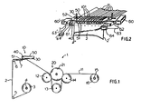
- the appratus 1 in accordance with the present invention comprises a supply spindle 4 which receives a rolled web 3 of fabric which has a plurality of patterns printed or woven thereon.
- the web 2 is held under tension by spindle 4 and travels around guide rollers 5 and 6 to a cutting station 10 which comprises a cutting support of platen 7 which extends the entire width of the web 2 and a plurality of blade holders 50 each of which have a blade 51 held therein and each mounted at the two ends by mounting bar 30 and nylon rod 40.
- the strips 11 are taken off through a drive mechanism 20 including three driven rollers 12, 13 and 14 and a flexible pressure roller 21 which will be described hereinafter.
- the driven strips 11 are then taken off onto roller 15 to form individual rolls 16 or the strips 11 can be taken off for addition processing.
- FIG 2 shows the cutting station 10 in more detail.
- the web 2 which is under tension, is driven through the cutting station so as to be split up into individual strips 11.
- This is carried out by a plurality of blades 51 each of which is mounted in a blade holder 50.
- the blade holders 50 have a front end through which a nylon rod 40 extends and to which each blade holder 50 is rigidly connected.
- the other end of each blade holder 50 is connected to a rigid mounting bar 30.
- the two ends of each blade holder 50 are interconnected by a spring steel parallelogram linkage 52 which will be described in more detail with reference to Figures 3 and 4.
- bar 30 are connected to flexible spring steel plates to allow a shifting thereof to the right or left as will be explained in more detail with reference to Figures 5 and 6.
- the blades 51 are able to follow the pattern of the fabric web 2 even if there is a lateral shifting thereof as it unwinds from roll 3.
- ribbons having substantially straight edges may be produced with a uniform pattern thereon.
- the shifting of the righthand blade to follow the lateral shifting of a pattern near edge 2' of the web 2 can be carried out by an operator stationed at the right side of the apparatus and manually moving the right side of rod 40 to keep it aligned with the movement of a pattern near edge 2' and similarly the shifting of the lefthand blade to follow the lateral shifting of a pattern near edge 2" of the web 2 can be carried out by an operator stationed at the left side of the apparatus and manually moving the left side of rod 40 to keep it aligned with the movement of a pattern near edge 2".
- each operator by following his own pattern at each side will compensate for the stretching, shrinkage and lateral displacement of the patterns on the web and by such action will proportionately distribute the cut of all the blades in between.
- optoelectric means 64 and 64' are provided which sense the position of a pattern near edge 2' and a pattern near edge 2" respectively, during the moving of the web through the cutting station 10.
- the output of the optoelectric sensors 64 and 64' are fed via lines 63 and 63' to servo mechanisms 60, 60' respectively which effect the movement and stretching or releasing of the rod 40 to the left and right consistent with the movement of the patterns near edge 2' and 2".
- the mechanisms 60, 60' are connected to ends of rod 40 by connecting members 61, 62.
- FIGS 3 and 4 show the blade holder 50 in accordance with the present invention.
- the blade holding end 54 of the blade holder 50 has a cutout 511 for receiving a blade 51 as shown.
- the blade is held in place by means of a mounting screw 512.
- End 54 also includes a clamping mechanism for rigidly connecting the end 54 to the nylon rod 40.
- the clamping mechanism includes clamping member 541 which is opposite a depression 542 which receives nylon rod 40 therein.
- the clamping member 541 is clamped against the rod 40 by means of screw 543 which is engaged in the threaded hole 545.
- the other end 53 of the blade holder has a cutout 531 for receiving mounting bar 30 therein with a flattened edge 31 thereof in the position shown.
- End 53 includes a clamping mechanism for rigidly connecting the end 53 to the bar 30 and this clamping mechanism includes the clamping screw 532 which is received through threaded hole 533 and which is rotated until the end of the screw contacts the flattened surface 31 of bar 30.
- the parallelogram linkage 52 comprises two flexure plates 521, 522 which are composed of spring tempered steel and are preferably 0,1 cm (0.05") thick.
- the plates 521, 522 have flexure hinges comprising thin sections 527-530 therein which have a thickness of approximately 0,02 cm (0.01").
- the plates 521, 522 are connected to the ends 53, 54 at portions 534 and 513 respectively by means of connecting screws 523-526.
- the dotted lines show the typical offset position that can be achieved by the parellologram linkage and this is characteristically approximately plus or minus 8 mm (5/16"). Whatever the degree the effort is, however, the knife blade remains parallel to its normal position.
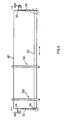
- mounting bar 30 is capable of shifting from the left to the right by means of the linkage including flexible spring steel plates 32, 33 connected at either end thereof. These plates 32, 33 are connected to mounting blocks 34, 35 which are in turn connected to mounting tabs 100 from the machine frame.
- This mounting configuration supports the mounting bar such that it is well constrained in all axes (rotational and translational) exceptfortrans- lation along its length (transverse motion with respect to the web).
- the parallelogram linkage is constructed such that its spring constant is much less than that of the combined spring constant of a number of knife holders (e.g. 5 holders or more). This means that in the configuration of Figures 5 and 6, if the nylon rod is pulled to one side, the knife holder parallelograms will deflect very little but the mounting bar linkage will deflect a great deal.
- the mounting bar 30 In its rest position, the mounting bar 30 is centered within the machine frame and it is in this position when the knife holders are initially fastened to it. That is, the blade holders 50 are unclamped at ends 53 and 54 and placed at desired spaced apart positions corresponding to the pattern on the web to be cut. The clamping screws 532 and 543 are then tightened to fix the holders in place on bar 30 and rod 40. As the web is unwound and carried past the cutting knives, the position of the nylon rod 40 (and therefore the knives) is adjusted in response to variation in the pattern on the web. If theweb is simply translated left or right, the mounting bar will shift accordingly on its parallelogram thus requiring no deflection in the knife holder parallelograms.
- the mounting bar linkage will remain in its rest position but the knife holder linkages will deflect in varying amounts to follow the nylon rod position. Subsequently, in cases where both growth (or shrinkage) and translation are required, the knife holder linkages will accommodate the growth/shrinkage and the mounting bar linkage will accommodate the translational offset.
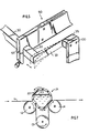
- Fig. 7 shows the drive system 20 for the web material and includes the three driven rollers 12-14 with arrows thereon showing the sense of rotation of each.
- the web 11 is held in contact with the driven rollers 12 and 14 by means of a flexible roller21 which comprises flexible rubber tubing 22 which is filled with a liquid 23 which is preferably water.
- the ends of the tube 22 are sealed and the tube 22 is allowed to rest againstthe rollers 12 and 14 with the web 11 therebetween.
- FIG. 7 Another feature of the drive system of Fig. 7 is the tension amplification afforded by the "windlass effect" resulting from the appropriate positioning of the three drive rollers.
- the flexible roller provides very uniform pinching force, the magnitude of this force is not great enough for most practical applications.
- the relatively weak but uniform, pinch force developed at roller 14 is amplified by the contact angle ofthe web with rollers 12 and 13 (i.e., a small traction force at roller 14 results in a proportional traction force of much greater magnitude at rollers 12 and 13).
Landscapes
- Life Sciences & Earth Sciences (AREA)
- Forests & Forestry (AREA)
- Engineering & Computer Science (AREA)
- Mechanical Engineering (AREA)
- Treatment Of Fiber Materials (AREA)
Claims (10)
Applications Claiming Priority (2)
| Application Number | Priority Date | Filing Date | Title |
|---|---|---|---|
| US823949 | 1986-01-29 | ||
| US06/823,949 US4674380A (en) | 1986-01-29 | 1986-01-29 | Apparatus for cutting ribbon |
Publications (2)
| Publication Number | Publication Date |
|---|---|
| EP0234756A1 EP0234756A1 (de) | 1987-09-02 |
| EP0234756B1 true EP0234756B1 (de) | 1991-01-23 |
Family
ID=25240216
Family Applications (1)
| Application Number | Title | Priority Date | Filing Date |
|---|---|---|---|
| EP19870300790 Expired - Lifetime EP0234756B1 (de) | 1986-01-29 | 1987-01-29 | Einrichtung zum Schneiden von Bahnen in Streifen |
Country Status (4)
| Country | Link |
|---|---|
| US (1) | US4674380A (de) |
| EP (1) | EP0234756B1 (de) |
| AU (1) | AU578208B2 (de) |
| DE (1) | DE3767503D1 (de) |
Families Citing this family (10)
| Publication number | Priority date | Publication date | Assignee | Title |
|---|---|---|---|---|
| US4883335A (en) * | 1986-01-06 | 1989-11-28 | American Telephone And Telegraph Company | Single-mode optical fiber tap |
| US4819528A (en) * | 1987-12-03 | 1989-04-11 | Essex Manufacturing Company | Ribbon cutting apparatus having multiple, independently driven groups of cutting blades |
| AU606487B2 (en) * | 1987-12-19 | 1991-02-07 | Sumitomo Rubber Industries, Ltd. | Method for correcting tyre deflection in tyre grooving and apparatus therefor |
| EP0381777B1 (de) * | 1988-07-28 | 1995-03-01 | Sumitomo Rubber Industries, Co. Ltd | Reifenrillenvorrichtung und verfahren |
| US5121885A (en) * | 1991-01-02 | 1992-06-16 | Chipman Donald I | Sheet fabric slitter and reroller |
| EP0710531B1 (de) * | 1994-11-07 | 2000-04-12 | Eastman Kodak Company | Vorrichtung und Verfahren zum Langsscheiden von Bandmaterial |
| US6148871A (en) * | 1998-11-02 | 2000-11-21 | Spring Industries, Inc. | Woven fabric with flat film warp yarns |
| CN107055186A (zh) * | 2017-04-25 | 2017-08-18 | 深圳正峰印刷有限公司 | 高精度分条设备及其分条刀治具 |
| RU2680766C9 (ru) * | 2017-08-28 | 2020-03-18 | Виктория Анатольевна Бибикова | Трикотажная пряжа для ручного вязания и способ ее получения |
| CN111002378B (zh) * | 2019-12-06 | 2024-10-18 | 北京金辰西维科安全印务有限公司 | 一种剥离夹具 |
Family Cites Families (10)
| Publication number | Priority date | Publication date | Assignee | Title |
|---|---|---|---|---|
| US2623586A (en) * | 1949-01-25 | 1952-12-30 | Joseph M Volpi | Fabric slitting apparatus |
| US2593154A (en) * | 1950-01-18 | 1952-04-15 | David N Judelson | Machine for cutting webs of material into strips |
| US3407690A (en) * | 1966-12-12 | 1968-10-29 | Armstrong Cork Co | Method of trimming and cutting in register |
| US3682031A (en) * | 1970-06-29 | 1972-08-08 | Midland Ross Corp | Rewinding apparatus |
| US3699621A (en) * | 1970-12-16 | 1972-10-24 | Ici Ltd | Rollers |
| US3877119A (en) * | 1972-05-29 | 1975-04-15 | Mueller Franz | Apparatus for cutting pile fabric |
| DE2245355A1 (de) * | 1972-09-15 | 1974-03-21 | Kurt Warnke | Gatter-brotschneidemaschine |
| SE415347B (sv) * | 1978-12-07 | 1980-09-29 | Tetra Pak Int | Anordning for kantskerning av en lopande laminatbana |
| DE2917719A1 (de) * | 1979-05-02 | 1980-11-13 | Hillesheimer W Dipl Ing Kg | Transportables folienschneidgeraet |
| IT1186425B (it) * | 1985-12-11 | 1987-11-26 | Fici Finanz Ind Comm Immo | Macchina per il taglio di nastri continui in strisce,in particolare con cilindri di taglio variabili in dimensione |
-
1986
- 1986-01-29 US US06/823,949 patent/US4674380A/en not_active Expired - Fee Related
-
1987
- 1987-01-28 AU AU68067/87A patent/AU578208B2/en not_active Ceased
- 1987-01-29 DE DE8787300790T patent/DE3767503D1/de not_active Expired - Lifetime
- 1987-01-29 EP EP19870300790 patent/EP0234756B1/de not_active Expired - Lifetime
Also Published As
| Publication number | Publication date |
|---|---|
| DE3767503D1 (de) | 1991-02-28 |
| AU6806787A (en) | 1987-07-30 |
| AU578208B2 (en) | 1988-10-13 |
| US4674380A (en) | 1987-06-23 |
| EP0234756A1 (de) | 1987-09-02 |
Similar Documents
| Publication | Publication Date | Title |
|---|---|---|
| US4674380A (en) | Apparatus for cutting ribbon | |
| US4360356A (en) | Decurler apparatus | |
| CA1296084C (en) | System for processing a web | |
| US4697755A (en) | Rewinder with slitter | |
| EP0710531B1 (de) | Vorrichtung und Verfahren zum Langsscheiden von Bandmaterial | |
| EP0165824A2 (de) | Kaschiervorrichtung mit Ausdehnungsüberwachung | |
| EP0119255B1 (de) | Gewebebehandlungsvorrichtung | |
| EP0512060A1 (de) | System zur autonomen nachbehandlung einer materialbahn. | |
| US9981821B2 (en) | Splicing equipment for strips wound on a pair of spools | |
| US4400230A (en) | Label indexing and applicator apparatus | |
| GB1567243A (en) | Printing and die-cutting apparatus | |
| KR920007788A (ko) | 광선조절 창 덮개 | |
| JP2659033B2 (ja) | 包装材ウエッブの端同士を接続する装置 | |
| US5777878A (en) | Screen printing press having longitudinal, lateral and angular screen frame registration system and method | |
| CA2296118C (en) | An apparatus for guiding an endless paper web | |
| GB1569886A (en) | Splicing webs of sheet material | |
| US4819528A (en) | Ribbon cutting apparatus having multiple, independently driven groups of cutting blades | |
| CA1134201A (en) | Variable tape advance imprint marker | |
| US5787777A (en) | Cutting device for trimming printed paper packages in a packaging machine | |
| GB1573462A (en) | Adjustable compression roller apparatus | |
| US5179896A (en) | Indent printer for plastic pipe and method of use | |
| EP0176230A1 (de) | Wickelmaschine mit Längsschneidevorrichtung | |
| US3728921A (en) | Apparatus for cutting a web into sheets and positioning the sheets | |
| US6006669A (en) | Apparatus for affixing removable notes to a moving web | |
| EP0721904B1 (de) | Aufwickelvorrichtung |
Legal Events
| Date | Code | Title | Description |
|---|---|---|---|
| PUAI | Public reference made under article 153(3) epc to a published international application that has entered the european phase |
Free format text: ORIGINAL CODE: 0009012 |
|
| AK | Designated contracting states |
Kind code of ref document: A1 Designated state(s): CH DE FR GB IT LI |
|
| 17P | Request for examination filed |
Effective date: 19871022 |
|
| 17Q | First examination report despatched |
Effective date: 19890110 |
|
| GRAA | (expected) grant |
Free format text: ORIGINAL CODE: 0009210 |
|
| AK | Designated contracting states |
Kind code of ref document: B1 Designated state(s): CH DE FR GB IT LI |
|
| PG25 | Lapsed in a contracting state [announced via postgrant information from national office to epo] |
Ref country code: LI Effective date: 19910123 Ref country code: IT Free format text: LAPSE BECAUSE OF FAILURE TO SUBMIT A TRANSLATION OF THE DESCRIPTION OR TO PAY THE FEE WITHIN THE PRE;WARNING: LAPSES OF ITALIAN PATENTS WITH EFFECTIVE DATE BEFORE 2007 MAY HAVE OCCURRED AT ANY TIME BEFORE 2007. THE CORRECT EFFECTIVE DATE MAY BE DIFFERENT FROM THE ONE RECORDED.SCRIBED TIME-LIMIT Effective date: 19910123 Ref country code: FR Effective date: 19910123 Ref country code: CH Effective date: 19910123 |
|
| REF | Corresponds to: |
Ref document number: 3767503 Country of ref document: DE Date of ref document: 19910228 |
|
| PGFP | Annual fee paid to national office [announced via postgrant information from national office to epo] |
Ref country code: GB Payment date: 19910322 Year of fee payment: 5 |
|
| REG | Reference to a national code |
Ref country code: CH Ref legal event code: PL |
|
| EN | Fr: translation not filed | ||
| PG25 | Lapsed in a contracting state [announced via postgrant information from national office to epo] |
Ref country code: DE Effective date: 19911001 |
|
| PLBE | No opposition filed within time limit |
Free format text: ORIGINAL CODE: 0009261 |
|
| STAA | Information on the status of an ep patent application or granted ep patent |
Free format text: STATUS: NO OPPOSITION FILED WITHIN TIME LIMIT |
|
| 26N | No opposition filed | ||
| PG25 | Lapsed in a contracting state [announced via postgrant information from national office to epo] |
Ref country code: GB Effective date: 19920129 |
|
| GBPC | Gb: european patent ceased through non-payment of renewal fee |