EP0234691B1 - Vehicle roof opening mechanism - Google Patents
Vehicle roof opening mechanism Download PDFInfo
- Publication number
- EP0234691B1 EP0234691B1 EP87300241A EP87300241A EP0234691B1 EP 0234691 B1 EP0234691 B1 EP 0234691B1 EP 87300241 A EP87300241 A EP 87300241A EP 87300241 A EP87300241 A EP 87300241A EP 0234691 B1 EP0234691 B1 EP 0234691B1
- Authority
- EP
- European Patent Office
- Prior art keywords
- gear wheel
- strut
- vehicle roof
- roof
- rack
- Prior art date
- Legal status (The legal status is an assumption and is not a legal conclusion. Google has not performed a legal analysis and makes no representation as to the accuracy of the status listed.)
- Expired - Lifetime
Links
- 230000000903 blocking effect Effects 0.000 claims description 6
- 230000001419 dependent effect Effects 0.000 description 1
- 239000000463 material Substances 0.000 description 1
- 229920003023 plastic Polymers 0.000 description 1
- 239000004033 plastic Substances 0.000 description 1
Images


Classifications
-
- B—PERFORMING OPERATIONS; TRANSPORTING
- B60—VEHICLES IN GENERAL
- B60J—WINDOWS, WINDSCREENS, NON-FIXED ROOFS, DOORS, OR SIMILAR DEVICES FOR VEHICLES; REMOVABLE EXTERNAL PROTECTIVE COVERINGS SPECIALLY ADAPTED FOR VEHICLES
- B60J7/00—Non-fixed roofs; Roofs with movable panels, e.g. rotary sunroofs
- B60J7/02—Non-fixed roofs; Roofs with movable panels, e.g. rotary sunroofs of sliding type, e.g. comprising guide shoes
-
- B—PERFORMING OPERATIONS; TRANSPORTING
- B60—VEHICLES IN GENERAL
- B60J—WINDOWS, WINDSCREENS, NON-FIXED ROOFS, DOORS, OR SIMILAR DEVICES FOR VEHICLES; REMOVABLE EXTERNAL PROTECTIVE COVERINGS SPECIALLY ADAPTED FOR VEHICLES
- B60J7/00—Non-fixed roofs; Roofs with movable panels, e.g. rotary sunroofs
- B60J7/08—Non-fixed roofs; Roofs with movable panels, e.g. rotary sunroofs of non-sliding type, i.e. movable or removable roofs or panels, e.g. let-down tops or roofs capable of being easily detached or of assuming a collapsed or inoperative position
- B60J7/16—Non-fixed roofs; Roofs with movable panels, e.g. rotary sunroofs of non-sliding type, i.e. movable or removable roofs or panels, e.g. let-down tops or roofs capable of being easily detached or of assuming a collapsed or inoperative position non-foldable and rigid, e.g. a one-piece hard-top or a single rigid roof panel
- B60J7/1628—Non-fixed roofs; Roofs with movable panels, e.g. rotary sunroofs of non-sliding type, i.e. movable or removable roofs or panels, e.g. let-down tops or roofs capable of being easily detached or of assuming a collapsed or inoperative position non-foldable and rigid, e.g. a one-piece hard-top or a single rigid roof panel for covering the passenger compartment
- B60J7/1635—Non-fixed roofs; Roofs with movable panels, e.g. rotary sunroofs of non-sliding type, i.e. movable or removable roofs or panels, e.g. let-down tops or roofs capable of being easily detached or of assuming a collapsed or inoperative position non-foldable and rigid, e.g. a one-piece hard-top or a single rigid roof panel for covering the passenger compartment of non-convertible vehicles
- B60J7/1642—Roof panels, e.g. sunroofs or hatches, movable relative to the main roof structure, e.g. by lifting or pivoting
-
- Y—GENERAL TAGGING OF NEW TECHNOLOGICAL DEVELOPMENTS; GENERAL TAGGING OF CROSS-SECTIONAL TECHNOLOGIES SPANNING OVER SEVERAL SECTIONS OF THE IPC; TECHNICAL SUBJECTS COVERED BY FORMER USPC CROSS-REFERENCE ART COLLECTIONS [XRACs] AND DIGESTS
- Y10—TECHNICAL SUBJECTS COVERED BY FORMER USPC
- Y10T—TECHNICAL SUBJECTS COVERED BY FORMER US CLASSIFICATION
- Y10T292/00—Closure fasteners
- Y10T292/08—Bolts
- Y10T292/1043—Swinging
- Y10T292/1075—Operating means
- Y10T292/1094—Screw
Definitions
- This invention relates to a vehicle roof of the type having a roof opening, a panel which is pivotable about an axis located in the vicinity of its front edge at right angles to the longitudinal axis of the vehicle between a position in which it closes the roof opening and a position in which its rear edge is raised above the level of the vehicle roof, a strut having one end pivotally attached to the underside of the panel adjacent to its rear edge and having a rack comprising a series of uniformly spaced gear teeth on a side edge thereof, a gear wheel rotatably mounted on the underside of the vehicle roof adjacent to the rear edge of the roof opening, guide means for retaining the rack in driving engagement with the gear wheel, and drive means for effecting rotation of the gear wheel, stop means adjacent to the end of the strut opposite to that which is attached to the roof panel and a blocking lever pivotally mounted on the underside of the vehicle roof adjacent to the gear wheel and resiliently biased into a blocking position in which it is engageable with the stop means to prevent movement of the strut beyond the range
- the gear wheel is fast with a pinion mounted on a horizontal axle and the drive means comprises a worm wheel mounted with its axis vertical so as to engage with the pinion and a manually operable drive member fast with the worm wheel, and spring means engages with said horizontal axle so as to bias the pinion into engagement with the worm wheel.
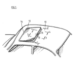
- roof 10 of a motor vehicle has an opening which is filled by panel 12 hinged along its leading edge 14 to a frame 16 which bounds the opening.
- An opening mechanism 18 at the rear of the panel 12 is arranged to hold the panel 12 in a fully open position as illustrated, in a fully closed position in which the panel 12 is level with the vehicle roof 10 and in a continuous range of intermediate positions between the closed position and the fully open position.
- the hinges (not shown) at the leading edge 14 of the panel 12 are constructed to allow the panel 12 to be disengaged from the frame 16 when the panel 12 is tilted beyond its fully open position illustrated in Figure 1.
- a clamping ring 20 ( Figures 3 to 5), secured to the bottom edge of the frame 16, engages with the underside of the vehicle roof 10 so as to hold the frame 16 in firm engagement therewith.
- the opening mechanism 18 comprises an arcuate strut 22 which is attached at one end to a bracket 24 attached to the underside of the roof panel 12 by means of a pivot pin 26.
- the strut 22 has a toothed rack; 28 formed on its radially outer edge, the rack 28 engaging with a pinion 30 which is journalled on a shaft 32.
- the shaft 32 is mounted on a bracket 34 which is secured to the frame 16 so as to project into the roof opening at approximately the central position along the rear edge thereof.
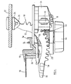
- a leaf spring 36 ( Figure 4), secured to the frame 16 adjacent to the bracket 34 engages with the radially inner edge of the arcuate strut 22 so as to bias the rack 28 into engagement with the pinion 30.
- a second pinion 42 which is engaged by a worm wheel 44 mounted on the bracket 34 with its axis vertical.
- a manually operable drive knob 46 is mounted fast with the worm wheel 44 below the bottom of the bracket 34 so as to be accessible from the inside of the vehicle.
- the end of the shaft 32 nearer to the pinion 42 is mounted in a slot 48 in the bracket 34 which is oriented to permit limited movement of the pinion 42 radially with respect to the axis with the worm wheel 44, the mounting 50 at the other end of the shaft 32 being constructed to allow limited pivotal movement.
- a spring 52 mounted on the bracket 34 adjacent to the slot 48, engages with the end of the shaft 32 to bias the pinion into engagement with the worm wheel 44.
- rotation of the knob 46 causes the worm wheel 44 to drive the pinion 42, which in turn causes the pinion 30 to drive the rack 28 so as to move it between a closed position, in which the pinion 30 engages with the end of the rack 28 nearer to the pivot pin 26 and the panel 12 is in engagement with seal projections 54 and 56 on the frame 16, and a fully open position in which the pinion 30 engages with the end of the rack 28 further from the pivot pin 26 and the panel 12 is disposed in the position illustrated in Figure 1.
- a first stop projection 58 ( Figures 4 and 5) is formed on a side face of the strut 22 so as to be engageable with a pawl tip 60 formed on a lever 62 which is mounted on a pivot pin 64 secured to the bracket 34.
- the lever 62 is formed from resilient plastics material and has an integral spring arm 64 which engages with a projection 66 on the bracket 34 to bias the pawl tip 60 into the position illustrated.
- the lever 62 also has a limb 68 which projects beyond the edge of the bracket 34 where it can be engaged by a user's finger so as to displace the pawl tip 60 away from the strut 22 and out of the path of the stop member 58.
- the rear edge of the panel 12 can now be pushed up manually beyond the position illustrated in Figure 1 but, unless the lever 62 is held in its displaced position, such upward movement is limited by engagement of the pawl tip 60 with a second stop projection 70 on the strut 22 beyond the first stop projection 58.
- the rear edge of the panel can not be lifted manually until the rack 28 is clear of the pinion 30 because such movement would be resisted by the worm wheel 44. The risk of inadvertently disengaging the strut 22 is therefore very small.
Landscapes
- Engineering & Computer Science (AREA)
- Mechanical Engineering (AREA)
- Body Structure For Vehicles (AREA)
- Power-Operated Mechanisms For Wings (AREA)
- Automatic Cycles, And Cycles In General (AREA)
- Vehicle Interior And Exterior Ornaments, Soundproofing, And Insulation (AREA)
Description
- This invention relates to a vehicle roof of the type having a roof opening, a panel which is pivotable about an axis located in the vicinity of its front edge at right angles to the longitudinal axis of the vehicle between a position in which it closes the roof opening and a position in which its rear edge is raised above the level of the vehicle roof, a strut having one end pivotally attached to the underside of the panel adjacent to its rear edge and having a rack comprising a series of uniformly spaced gear teeth on a side edge thereof, a gear wheel rotatably mounted on the underside of the vehicle roof adjacent to the rear edge of the roof opening, guide means for retaining the rack in driving engagement with the gear wheel, and drive means for effecting rotation of the gear wheel, stop means adjacent to the end of the strut opposite to that which is attached to the roof panel and a blocking lever pivotally mounted on the underside of the vehicle roof adjacent to the gear wheel and resiliently biased into a blocking position in which it is engageable with the stop means to prevent movement of the strut beyond the range of positions in which the gear wheel can engage with the rack, the blocking lever being manually displaceable into a release position allowing the stop means to pass. A roof of this type is disclosed in FR-A 2 548 978.
- According to the invention, in a roof of this type, the gear wheel is fast with a pinion mounted on a horizontal axle and the drive means comprises a worm wheel mounted with its axis vertical so as to engage with the pinion and a manually operable drive member fast with the worm wheel, and spring means engages with said horizontal axle so as to bias the pinion into engagement with the worm wheel.
- Preferred features of the invention are set out in the
dependent claims - An embodiment of the invention will now be described, by way of example, with reference to the accompanying drawings, in which;
- Figure 1 is a perspective view of a top of a motor car fitted with an opening roof of the type preferred to a bar, having a frame surrounding the roof opening and with the panel in the open position;
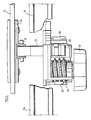
- Figure 2 is a partially broken away cross sectional view taken on the line 2 - 2 in Figure 1;
- Figure 3 is a cross sectional view taken on the line 3 - 3 in Figure 1;
- Figure 4 is a cross sectional view taken on the line 4 - 4 in Figure 1; and Figure 5 is a partly schematic plan view from below of the mechanism illustrated in Figures 2 to 4.
- Referring to Figure 1,
roof 10 of a motor vehicle has an opening which is filled bypanel 12 hinged along its leadingedge 14 to aframe 16 which bounds the opening. Anopening mechanism 18 at the rear of thepanel 12 is arranged to hold thepanel 12 in a fully open position as illustrated, in a fully closed position in which thepanel 12 is level with thevehicle roof 10 and in a continuous range of intermediate positions between the closed position and the fully open position. The hinges (not shown) at the leadingedge 14 of thepanel 12 are constructed to allow thepanel 12 to be disengaged from theframe 16 when thepanel 12 is tilted beyond its fully open position illustrated in Figure 1. A clamping ring 20 (Figures 3 to 5), secured to the bottom edge of theframe 16, engages with the underside of thevehicle roof 10 so as to hold theframe 16 in firm engagement therewith. - Referring to Figures 2 to 5, the
opening mechanism 18 comprises anarcuate strut 22 which is attached at one end to abracket 24 attached to the underside of theroof panel 12 by means of apivot pin 26. Thestrut 22 has a toothed rack; 28 formed on its radially outer edge, therack 28 engaging with apinion 30 which is journalled on ashaft 32. Theshaft 32 is mounted on abracket 34 which is secured to theframe 16 so as to project into the roof opening at approximately the central position along the rear edge thereof. A leaf spring 36 (Figure 4), secured to theframe 16 adjacent to thebracket 34 engages with the radially inner edge of thearcuate strut 22 so as to bias therack 28 into engagement with thepinion 30. - Also journalled on the
shaft 32 and secured fast with thepinion 30 is asecond pinion 42 which is engaged by aworm wheel 44 mounted on thebracket 34 with its axis vertical. A manuallyoperable drive knob 46 is mounted fast with theworm wheel 44 below the bottom of thebracket 34 so as to be accessible from the inside of the vehicle. In order to ensure rattle-free engagement between theworm wheel 44 and thepinion 42, the end of theshaft 32 nearer to thepinion 42 is mounted in aslot 48 in thebracket 34 which is oriented to permit limited movement of thepinion 42 radially with respect to the axis with theworm wheel 44, themounting 50 at the other end of theshaft 32 being constructed to allow limited pivotal movement. Aspring 52, mounted on thebracket 34 adjacent to theslot 48, engages with the end of theshaft 32 to bias the pinion into engagement with theworm wheel 44. - In use, rotation of the
knob 46 causes theworm wheel 44 to drive thepinion 42, which in turn causes thepinion 30 to drive therack 28 so as to move it between a closed position, in which thepinion 30 engages with the end of therack 28 nearer to thepivot pin 26 and thepanel 12 is in engagement withseal projections frame 16, and a fully open position in which thepinion 30 engages with the end of therack 28 further from thepivot pin 26 and thepanel 12 is disposed in the position illustrated in Figure 1. - In order to prevent the
knob 46 being rotated sufficiently to drive thepinion 30 off the end of the rack further from thepivot pin 26, a first stop projection 58 (Figures 4 and 5) is formed on a side face of thestrut 22 so as to be engageable with apawl tip 60 formed on alever 62 which is mounted on apivot pin 64 secured to thebracket 34. Thelever 62 is formed from resilient plastics material and has anintegral spring arm 64 which engages with aprojection 66 on thebracket 34 to bias thepawl tip 60 into the position illustrated. Thelever 62 also has alimb 68 which projects beyond the edge of thebracket 34 where it can be engaged by a user's finger so as to displace thepawl tip 60 away from thestrut 22 and out of the path of thestop member 58. The rear edge of thepanel 12 can now be pushed up manually beyond the position illustrated in Figure 1 but, unless thelever 62 is held in its displaced position, such upward movement is limited by engagement of thepawl tip 60 with asecond stop projection 70 on thestrut 22 beyond thefirst stop projection 58. Thus, in order to free thestrut 22 completely, it is necessary first to hold thelever 62 in its displaced position while rotating thedrive wheel 46 and then to continue to hold thelever 62 while manually lifting the rear edge of the panel. The rear edge of the panel can not be lifted manually until therack 28 is clear of thepinion 30 because such movement would be resisted by theworm wheel 44. The risk of inadvertently disengaging thestrut 22 is therefore very small.
Claims (3)
Applications Claiming Priority (2)
| Application Number | Priority Date | Filing Date | Title |
|---|---|---|---|
| GB8601207 | 1986-01-18 | ||
| GB8601207A GB2185525B (en) | 1986-01-18 | 1986-01-18 | Vehicle roof opening mechanism |
Publications (3)
| Publication Number | Publication Date |
|---|---|
| EP0234691A2 EP0234691A2 (en) | 1987-09-02 |
| EP0234691A3 EP0234691A3 (en) | 1989-02-08 |
| EP0234691B1 true EP0234691B1 (en) | 1990-07-25 |
Family
ID=10591592
Family Applications (1)
| Application Number | Title | Priority Date | Filing Date |
|---|---|---|---|
| EP87300241A Expired - Lifetime EP0234691B1 (en) | 1986-01-18 | 1987-01-12 | Vehicle roof opening mechanism |
Country Status (9)
| Country | Link |
|---|---|
| US (1) | US4725093A (en) |
| EP (1) | EP0234691B1 (en) |
| JP (1) | JPS62166112A (en) |
| KR (1) | KR870007007A (en) |
| AU (1) | AU579954B2 (en) |
| BR (1) | BR8700162A (en) |
| CA (1) | CA1281350C (en) |
| DE (1) | DE3763859D1 (en) |
| GB (1) | GB2185525B (en) |
Families Citing this family (5)
| Publication number | Priority date | Publication date | Assignee | Title |
|---|---|---|---|---|
| ES2029223T3 (en) * | 1987-09-25 | 1993-06-16 | Zani S.R.L | OPENING AND CLOSING CONTROLS FOR VEHICLE ROOFS. |
| JPH0196327U (en) * | 1987-12-21 | 1989-06-27 | ||
| US5401453A (en) * | 1993-02-17 | 1995-03-28 | Mid-American Products, Inc. | Method of forming a vehicle window frame with a seal insert |
| US6692245B1 (en) | 1997-08-18 | 2004-02-17 | Ipl Inc. | Mold for making a window frame |
| US6637157B1 (en) * | 1999-12-10 | 2003-10-28 | Delphi Technologies, Inc. | Vehicle liftgate power operating system |
Family Cites Families (10)
| Publication number | Priority date | Publication date | Assignee | Title |
|---|---|---|---|---|
| GB595485A (en) * | 1945-07-05 | 1947-12-05 | Worcester Windshields & Caseme | Improvements in means for adjusting or regulating windshields and other angularly-movable panels |
| GB197589A (en) * | 1922-07-28 | 1923-05-17 | Charles Yeomans Hopkins | Improved opening and closing devices for fanlight windows and the like |
| GB298500A (en) * | 1928-07-05 | 1928-10-02 | John Harold Smith Wright | Improvements in and relating to wind screens for motor cars and the like |
| GB1091528A (en) * | 1963-08-26 | 1967-11-15 | Teleflex Prod Ltd | Improvements in gearing for adjusting windows and other angularly movable panels |
| US3979148A (en) * | 1975-06-12 | 1976-09-07 | Wayne Martin | Window frame apparatus for vehicles |
| FR2397512B1 (en) * | 1977-07-11 | 1986-05-02 | Mecanismes Comp Ind De | DEVICE FOR CLOSING A SLIDING MEMBER, IN PARTICULAR OF A SUNROOF OF A MOTOR VEHICLE |
| DE3045363A1 (en) * | 1980-12-02 | 1982-07-08 | Karosseriewerke Weinsberg Gmbh, 7102 Weinsberg | VEHICLE ROOF |
| DE3324949A1 (en) * | 1983-07-11 | 1985-01-24 | Karosseriewerke Weinsberg Gmbh, 7102 Weinsberg | Extendable and removable roof component for motor vehicles |
| US4617758A (en) * | 1984-01-23 | 1986-10-21 | Truth Inc. | Self-locking window operator |
| EP0172869B1 (en) * | 1984-03-06 | 1988-10-05 | Webasto AG Fahrzeugtechnik | Actuator for an openable vehicle roof |
-
1986
- 1986-01-18 GB GB8601207A patent/GB2185525B/en not_active Expired
-
1987
- 1987-01-05 AU AU67125/87A patent/AU579954B2/en not_active Ceased
- 1987-01-12 DE DE8787300241T patent/DE3763859D1/en not_active Expired - Fee Related
- 1987-01-12 EP EP87300241A patent/EP0234691B1/en not_active Expired - Lifetime
- 1987-01-12 CA CA000527158A patent/CA1281350C/en not_active Expired - Lifetime
- 1987-01-13 US US07/002,964 patent/US4725093A/en not_active Expired - Fee Related
- 1987-01-14 JP JP62007392A patent/JPS62166112A/en active Pending
- 1987-01-16 BR BR8700162A patent/BR8700162A/en unknown
- 1987-01-17 KR KR870000327A patent/KR870007007A/en not_active Withdrawn
Also Published As
| Publication number | Publication date |
|---|---|
| BR8700162A (en) | 1987-12-08 |
| GB2185525B (en) | 1989-10-25 |
| AU579954B2 (en) | 1988-12-15 |
| AU6712587A (en) | 1987-07-23 |
| KR870007007A (en) | 1987-08-14 |
| DE3763859D1 (en) | 1990-08-30 |
| GB8601207D0 (en) | 1986-02-19 |
| JPS62166112A (en) | 1987-07-22 |
| US4725093A (en) | 1988-02-16 |
| EP0234691A2 (en) | 1987-09-02 |
| EP0234691A3 (en) | 1989-02-08 |
| CA1281350C (en) | 1991-03-12 |
| GB2185525A (en) | 1987-07-22 |
Similar Documents
| Publication | Publication Date | Title |
|---|---|---|
| US4759584A (en) | Beverage container holder for vehicles | |
| CA1230151A (en) | Sliding and venting sunroof | |
| US4925072A (en) | Locking mechanism for a pivotable closure | |
| US4962564A (en) | Concealed windshield wiper system | |
| CA1281350C (en) | Vehicle roof opening mechanism | |
| EP0551980B1 (en) | Latch for hinged panel | |
| US4194321A (en) | Oven hinge mechanism including detent lock | |
| JPS5946589B2 (en) | ashtray device | |
| CA1299219C (en) | Removable roof assembly with improved wind deflector | |
| US4819498A (en) | Tilt steering apparatus for vehicles | |
| EP0478156B1 (en) | Blind for vehicle opening roof | |
| JPH0728022Y2 (en) | Open car roof lock structure | |
| JPS63137021A (en) | Sliding roof for automobile | |
| JPS6271723A (en) | Sunroof apparatus for vehicle | |
| JPH0583414B2 (en) | ||
| JPH0634525Y2 (en) | Tightening handle with stopper for sliding door | |
| JPH0776227A (en) | Deflector devide for sunroof | |
| JPH0237283Y2 (en) | ||
| JP3734610B2 (en) | Tilt lock mechanism of rotating device | |
| EP0255417B1 (en) | Actuating device for a sliding window of a motor vehicle door | |
| JPH089857Y2 (en) | Switch support device | |
| EP0507486A1 (en) | Vehicle opening roof | |
| JP2668342B2 (en) | Door stop holding device | |
| JPH0427688Y2 (en) | ||
| EP0885761A1 (en) | Open roof construction for a vehicle |
Legal Events
| Date | Code | Title | Description |
|---|---|---|---|
| PUAI | Public reference made under article 153(3) epc to a published international application that has entered the european phase |
Free format text: ORIGINAL CODE: 0009012 |
|
| AK | Designated contracting states |
Kind code of ref document: A2 Designated state(s): DE ES FR IT SE |
|
| PUAL | Search report despatched |
Free format text: ORIGINAL CODE: 0009013 |
|
| AK | Designated contracting states |
Kind code of ref document: A3 Designated state(s): DE ES FR IT SE |
|
| 17P | Request for examination filed |
Effective date: 19890608 |
|
| 17Q | First examination report despatched |
Effective date: 19891027 |
|
| GRAA | (expected) grant |
Free format text: ORIGINAL CODE: 0009210 |
|
| AK | Designated contracting states |
Kind code of ref document: B1 Designated state(s): DE ES FR IT SE |
|
| PG25 | Lapsed in a contracting state [announced via postgrant information from national office to epo] |
Ref country code: IT Free format text: LAPSE BECAUSE OF FAILURE TO SUBMIT A TRANSLATION OF THE DESCRIPTION OR TO PAY THE FEE WITHIN THE PRESCRIBED TIME-LIMIT;WARNING: LAPSES OF ITALIAN PATENTS WITH EFFECTIVE DATE BEFORE 2007 MAY HAVE OCCURRED AT ANY TIME BEFORE 2007. THE CORRECT EFFECTIVE DATE MAY BE DIFFERENT FROM THE ONE RECORDED. Effective date: 19900725 Ref country code: SE Effective date: 19900725 |
|
| REF | Corresponds to: |
Ref document number: 3763859 Country of ref document: DE Date of ref document: 19900830 |
|
| ET | Fr: translation filed | ||
| PG25 | Lapsed in a contracting state [announced via postgrant information from national office to epo] |
Ref country code: ES Free format text: LAPSE BECAUSE OF FAILURE TO SUBMIT A TRANSLATION OF THE DESCRIPTION OR TO PAY THE FEE WITHIN THE PRESCRIBED TIME-LIMIT Effective date: 19901105 |
|
| PLBE | No opposition filed within time limit |
Free format text: ORIGINAL CODE: 0009261 |
|
| STAA | Information on the status of an ep patent application or granted ep patent |
Free format text: STATUS: NO OPPOSITION FILED WITHIN TIME LIMIT |
|
| 26N | No opposition filed | ||
| PGFP | Annual fee paid to national office [announced via postgrant information from national office to epo] |
Ref country code: DE Payment date: 19960115 Year of fee payment: 10 |
|
| PG25 | Lapsed in a contracting state [announced via postgrant information from national office to epo] |
Ref country code: DE Effective date: 19971001 |
|
| PGFP | Annual fee paid to national office [announced via postgrant information from national office to epo] |
Ref country code: FR Payment date: 19980129 Year of fee payment: 12 |
|
| PG25 | Lapsed in a contracting state [announced via postgrant information from national office to epo] |
Ref country code: FR Free format text: LAPSE BECAUSE OF NON-PAYMENT OF DUE FEES Effective date: 19990930 |
|
| REG | Reference to a national code |
Ref country code: FR Ref legal event code: ST |