EP0233850B1 - Arrangement for controlled damping of pivoting movements in an articulated bus - Google Patents
Arrangement for controlled damping of pivoting movements in an articulated bus Download PDFInfo
- Publication number
- EP0233850B1 EP0233850B1 EP87850037A EP87850037A EP0233850B1 EP 0233850 B1 EP0233850 B1 EP 0233850B1 EP 87850037 A EP87850037 A EP 87850037A EP 87850037 A EP87850037 A EP 87850037A EP 0233850 B1 EP0233850 B1 EP 0233850B1
- Authority
- EP
- European Patent Office
- Prior art keywords
- vehicle
- control system
- damping
- hydraulic
- throttle
- Prior art date
- Legal status (The legal status is an assumption and is not a legal conclusion. Google has not performed a legal analysis and makes no representation as to the accuracy of the status listed.)
- Expired
Links
- 238000013016 damping Methods 0.000 title claims description 36
- 230000004044 response Effects 0.000 claims description 10
- 239000012530 fluid Substances 0.000 description 21
- 230000000903 blocking effect Effects 0.000 description 9
- 238000006073 displacement reaction Methods 0.000 description 9
- 230000000694 effects Effects 0.000 description 3
- 230000002159 abnormal effect Effects 0.000 description 2
- 230000008878 coupling Effects 0.000 description 2
- 238000010168 coupling process Methods 0.000 description 2
- 238000005859 coupling reaction Methods 0.000 description 2
- 230000003213 activating effect Effects 0.000 description 1
- 230000008859 change Effects 0.000 description 1
- 238000004891 communication Methods 0.000 description 1
- 238000012937 correction Methods 0.000 description 1
- 230000007812 deficiency Effects 0.000 description 1
- 238000010586 diagram Methods 0.000 description 1
- 238000005096 rolling process Methods 0.000 description 1
- 230000007704 transition Effects 0.000 description 1
- 230000001960 triggered effect Effects 0.000 description 1
Images

Classifications
-
- B—PERFORMING OPERATIONS; TRANSPORTING
- B62—LAND VEHICLES FOR TRAVELLING OTHERWISE THAN ON RAILS
- B62D—MOTOR VEHICLES; TRAILERS
- B62D53/00—Tractor-trailer combinations; Road trains
- B62D53/04—Tractor-trailer combinations; Road trains comprising a vehicle carrying an essential part of the other vehicle's load by having supporting means for the front or rear part of the other vehicle
- B62D53/08—Fifth wheel traction couplings
- B62D53/0871—Fifth wheel traction couplings with stabilising means, e.g. to prevent jack-knifing, pitching, rolling, buck jumping
-
- B—PERFORMING OPERATIONS; TRANSPORTING
- B62—LAND VEHICLES FOR TRAVELLING OTHERWISE THAN ON RAILS
- B62D—MOTOR VEHICLES; TRAILERS
- B62D47/00—Motor vehicles or trailers predominantly for carrying passengers
- B62D47/02—Motor vehicles or trailers predominantly for carrying passengers for large numbers of passengers, e.g. omnibus
- B62D47/025—Motor vehicles or trailers predominantly for carrying passengers for large numbers of passengers, e.g. omnibus articulated buses with interconnecting passageway, e.g. bellows
Definitions
- the present invention relates to an arrangement for controlled damping of pivoting movements in a vehicle with two vehicle units pivotally joined to each other, particularly an articulated bus, as defined in the introductory portion of claim 1.
- pivot blocks In order to limit uncontrolled angular displacement in articulated vehicles, a number of different types of pivot blocks have been developed, intended to he activated when critical situations arise.
- One of the most well known arrangements in this respect is based on disposing hydraulic cylinders between the vehicle units, usually one hydraulic cylinder on either side of the longitudinal axis or the vehicle and a pivot plate or the like joining the vehicle units.
- the respective ends of the hydraulic cylinders are fixed to the vehicle units, and the hydraulic cylinders communicate with each other via a connecting line. Hydraulic fluid flows through said line to and from each cylinder depending on the angular displacement of the vehicle units. Should the rate of angular displacement be abnormally high, a blocking means is activated which completely or partially blocks the throughflow in the connecting line and thus prevents further angular displacement.
- Sensing the rate of angular displacement by sensing the hydraulic fluid flow rate presents problems, however, in selecting a suitable critical boundary value for activating the pivot block.
- the system Under normal operating conditions, which includes turning at both low and high speed, the system should not be over-sensitive, but at the same time the system must be sufficiently sensitive to react quickly to an abnormal angular displacement. In certain cases, such an uncontrolled angular displacement can even happen relatively slowly.
- boundary values for blocking actuation which are compromises. This means that such an angular blocking means will be activated under certain operating conditions when it should not be, and vice versa.
- Another general solution is based on arranging means which sense the pivot angle between the vehicle units and means which sense the vehicle steering angle. Signals corresponding to these values are compared and if the pivot angle is greater than what is warranted by the prevailing steering angle, blocking means are activated which prevent continued pivot angle increase.
- so-called high-speed damping in is sensed when the vehicle exceeds a certain high speed and when the steering angle exceeds a certain loin value.
- a powerful damping is triggered by coupling in a throttle in a connecting line between the dampers.
- additional throttles in the connecting line to thus be able to engage a lower degree of damping at lower speeds and at lesser steering angles.
- DE-A-3 405 871 shows an arrangement where the vehicle speed is used to control a throttle so that the damping increases with speed.
- sensors for sensing the pivot angle are also sensors for sensing the pivot angle, but the pivot angle signal is only used together with a signal representing the steering angle for calculating an allowable value of the pivot angle. If the pivot angle is larger than called for by the magnitude of the steering angle a blocking arrangement is activated in order to prevent further increase of the pivot angle.
- GB-A-2 069 428 also that it is known to vary the damping in response to the vehicle speed. It further shows that the damping can he varied in response to the steering angle, and that various combinations of vehicle speed and steering angle can provide various degrees of damping. Here too a signal representing the pivot angle is used only for comparison with the steering angle and for blocking the joint when need arises.
- the present invention has the purpose of limiting, for articulated vehicles, particularly articulated buses, the occurrence of uncontrolled pivoting movements in a manned which does not have the disadvantages occurring in known solutions.
- the purpose of the invention is thus to provide an arrangement for damping of the pivoting movements at a plurality of different levels depending on appropriate vehicle parameters, the electrical control system of the arrangement being arranged to connect the various throttles in response to parameter values representing the pivot angle and the vehicle speed.
- the damping between the vehicle units By allowing the magnitude of the pivot angle and the vehicle speed to control, in accordance with the invention, the damping between the vehicle units, the damping for each particular driving situation can be optimized.
- the damping can be selected at a number of different levels and the transitons between the various levels can be made softly, which gives the vehicle a stable feel when driving.
- a vehicle in particular an articulated bus 1, comprises a forward vehicle unit 2 and a rear vehicle unit 3, which are articulated to each other via a pivot joint 4.
- the forward vehicle unit 2 comprises a front axle carrying steered wheels and a middle axle carrying free rolling wheels (not shown).
- the rear vehicle unit 3 comprises a rear shaft carrying drive wheels (not shown), which are drivingly connected in a conventional manner to a drive unit arranged in the rear vehicle unit 3.
- the pivot joint 4 is made up of two pivot plates, of which the upper plate is securely fixed to the rear vehicle unit 3, and the lower plate is securely fixed to the forward vehicle unit 2. Said plates slide against each other and are fixed horizontally to each other by a central vertical pivot bolt 7 (shown only schematically here as a pivot point), about which the plates and thus also the vehicle units 2,3 can pivot relative to each other.
- the sensing of the relative pivoting between the vehicle units 2, 3, the pivot angle a is carried out with the help of four no-contact position sensors 8 fixed to the upper pivot plate 5 which is securely fixed to the rear vehicle unit 3.
- the sensors 8 are placed in a row in the radial direction from the pivot point 7 of the joint 4 and parallel to the longitudinal axis 10 of the rear vehicle unit 3.
- the sensors 8 cooperate with a cam disc 11 fixed to the lower pivot plate, said cam disc being provided with four radial steps 12 arranged symmetrically on either side of the longitudinal axis 9 of the forward vehicle unit 2.
- Fig. 1 the dimensions of the cam disc 11 have been exaggerated to more clearly reveal its shape.
- the steps 12 of the cam disc 11 are arranged to be sensed during the pivot movement, and each step 12, can only be sensed by one of the four sensors 8.
- the steps 12 represent different angle sectors, and by sensing which of the steps 12 is in front of its respective sensor 8, an indication is given of the pivot angle a between the vehicle units 2, 3.
- One step 14 is selected so that a sensor 8 senses when the pivot angle is greater than 9 degrees.
- the rest of the steps 12 are selected so that a sensor is activated when exceeding angles of 18 degrees, 30 degrees and 47 degrees, respectively.
- the maximum pivot angle is circa 50 degrees.
- a pivot angle of o degrees corresponds to driving straight ahead.
- a fifth positional sensor 13 is arranged analogously to the four other sensors 8 and interacts with a groove 14 in the cam disc 11. Said groove 14 extends along the cam disc 11 only on one side of the longitudinal axis 9 of the forward vehicle unit 2.
- the fifth sensor 13 is used to indicate in which direction the pivoting occurs.
- the signals from the respective sensors 8, 13 are led to an electronic control unit 15, which transforms in a conventional manner the respective signals to suitable signals representing the various pivot angles and the direction of pivoting.
- the connection of the sensors 8, 13 to the control unit 15 have only been represented schematically.
- the control unit 15 is also connected to a speed sensor 16, which provides a signal representing the speed of the vehicle 1.
- this sensor 16 is arranged to sense the rotational speed of a propeller shaft between the vehicle drive unit and its driven wheels. Since its design is wellknown, it will not be described in more detail here.
- the pistons 20 divide each cylinder 19 into a forward chamber 24, 25 and a rear chamber 26, 27.
- the chambers 24 - 27 are connected crosswise to each other, so that the forward chamber 24 in one damper 17 communicates with the rear chamber 27 in the other damper 18 and vice versa.
- two cooperating spaces 24, 27 and 25, 26 are formed, said spaces being connected via a first and a second hydraulic line 31, 32 to a hydraulic control system 30, which is represented schematically in Fig. 1.
- the two spaces 24, 27 and 25. 26, respectively, are also connected via the control system 30 to each other.
- the first hydraulic line 31 is connected to a first branch point 33, to which there are also connected a first and a second non-return valve 34, 35.
- the first non-return valve 34 permits flow only from the branch point 33, while the second non-return valve 35 permits flow only to the branch point 33.
- the second hydraulic line 32 is connected to a second branch point 36, to which a third non-return valve 37 is connected which only permits flow from the branch point 36, and a fourth non-return valve 38 is connected which only permits flow to the branch point 36.
- the first and the third non-return valves 34, 37 are connected to each other via a third hydraulic line 39.
- the second and the fourth non-return valves 35, 38 are also connected to each other via a fourth hydraulic line 40.
- a second switch valve 42 is arranged parallel to the fourth non-return valve 38.
- the third and fourth lines 39, 40 are joined to each other via three throttle lines 43, 44, 45 coupled in parallel.
- the first throttle line 43 comprises only a fixed first constriction 46.
- the second throttle line 44 comprises a fixed second constriction 47 in series with an electromagnetic valve 48, which has a normally open position and an activated closed position.
- the third throttle line 45 comprises a fixed third constriction 49 in series with an electromagnetic valve 50, which has a normally open position and an activated closed position.
- the three throttle lines 43, 44, 45 are connected at their respective ends via a fifth hydraulic line 51 to a third branch point 52 on the third line 39. At their respective other ends the throttle lines 43, 44, 45 are connected to a fourth branch point 53 on the fourth line 40.
- An overflow valve 54 is coupled between this fifth line 51 and the fourth line 40, so that if the pressure in the fifth line 51 should exceed a certain value, hydraulic fluid will flow directly to the fourth line 40. Under all normal operating conditions, however, the overflow valve 54 is closed.
- An accumulator tank 55 is also connected to the fourth line 40 at the fourth branch point 53. Hydraulic fluid can be directed to and from this tank as the volume varies in the hydraulic system. Such variations if volume can be caused by the volume in the different chambers 24 - 27 of the dampers 17, 18 being different due to space requirements of the piston rod 21 or temperature variations in the hydraulic fluid.
- the electromagnetic valves 41, 42, 48, 50 of the hydraulic control system 30 are controlled in response to signals from the electrical control system 15.
- the connections of the electrical control system 15 to the valves 41, 42, 48, 50 is only schematically represented as four lines 56 between the control systems 15, 30.
- the electrical control system 15 includes a program which, in response to input signals from the sensors 8, 13 and 16, sensing the pivot angle, the pivoting direction and the vehicle speed, activates the various valves 41, 42, 48, 50.
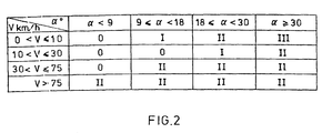
- the accompanying Fig. 2 shows in tabular form how the various degrees of damping are obtained in response to the pivot angle a and the vehicle speed v. As can be seen from Fig. 2, the intervals in question for the pivot angle agree with those sensed by the sensors 8. 0 indicates that no or virtually no damping is provided, I indicates that the damping is week, II that the damping is moderate and III that the damping is hard.
- damping When damping is at level 0, there is an exchange of hydraulic fluid in the respective chambers 24 - 27 of the dampers 17, 18 without any obstacle.
- the control system 30 merely acts as a communication between the respective spaces 24, 27 and 25, 26.
- the two switch valves 41, 42 assume their normally open positions which allows hydraulic fluid from the first hydraulic line 31 to flow via the first switch valve 41, the fourth hydraulic line 40 and the second switch valve 42 to the second hydraulic line 32.
- Damping at level 0 occurs primarily when driving straight ahead or at small pivot angles a, for example less than 9 degrees, at speeds v of less than a relatively high vehicle speed, for example 75 km/h.
- Damping at level I corresponds to a soft damping which occurs at moderate pivot angles a at low vehicle speeds v, and Fig. 2 gives exemplifying boundary values.
- the position sensors 8, 13 sense its magnitude and direction.
- Hydraulic fluid flows to the hydraulic control system via the first hydraulic fluid line 31.
- the first switch valve 41 is activated by the electrical control system in response to signals representing the pivoting direction, whereupon this valve 41 assumes its closed position. The hydraulic fluid therefore flows via the second non-return valve 34 to the third hydraulic line 39.
- the hydraulic fluid will then be conducted from the second line 32 via the second switch valve 42, the fourth line 40 and via the first non-return valve 35 to the first line 31.
- the throttles 46, 47, 49 will not have any damping effect.
- the dampers 17, 18 will thus only have a damping effect as the vehicle units 2, 3 are folded towards each other, while no damping is obtained when straightening them out.
- the second switch valve 42 is activated instead of the first switch valve 41. Otherwise, hydraulic fluid flows analogously through the control system 30.
- Damping at level II is effected in the same manner as at level I, but the solenoid valve 48 is activated in the second throttle line 44. Thus fluid will only flow through two parallel throttle lines 46, 49.
- solenoid valve 50 in the third throttle line 45 is also activated, and fluid only flows through one throttle 46.
- the arrangement according to the invention makes it possible to dampen pivoting movements in response to both the magnitude of the angular displacement and the speed of the vehicle. An optimum damping can be obtained for each situation without it having a negative effect on other situations.
- the damping is arranged in a plurality of different levels, these can be selected so that the transition between the levels is hardly noticeable.
- the described embodiment has essentially conventional components and therefore the functional reliability can be kept high at the same time as costs are kept low.
Landscapes
- Engineering & Computer Science (AREA)
- Chemical & Material Sciences (AREA)
- Combustion & Propulsion (AREA)
- Transportation (AREA)
- Mechanical Engineering (AREA)
- Vehicle Body Suspensions (AREA)
Description
- The present invention relates to an arrangement for controlled damping of pivoting movements in a vehicle with two vehicle units pivotally joined to each other, particularly an articulated bus, as defined in the introductory portion of
claim 1. - In articulated vehicles, such as articulated buses, there is the risk, under abnormal operating conditions, that the two vehicle units may be subjected to uncontrolled pivoting movements relative to each other. This can result in them folding inwardly about a curve center in an uncontrolled manner, socalled jack-knifing, or outwardly from said curve center with the rear chassis being thrown outwardly. Such uncontrolled pivoting movements can result in dangerous traffic situations by the mere fact that the size or an articulated vehicle in general does not permit any corrections requiring any amount of space. The risk of uncontrolled angular movements is particularly noticeable in articulated vehicles in which the rearmost axle is driven, since this driving force pushes the rest of the vehicle.
- In order to limit uncontrolled angular displacement in articulated vehicles, a number of different types of pivot blocks have been developed, intended to he activated when critical situations arise. One of the most well known arrangements in this respect is based on disposing hydraulic cylinders between the vehicle units, usually one hydraulic cylinder on either side of the longitudinal axis or the vehicle and a pivot plate or the like joining the vehicle units. The respective ends of the hydraulic cylinders are fixed to the vehicle units, and the hydraulic cylinders communicate with each other via a connecting line. Hydraulic fluid flows through said line to and from each cylinder depending on the angular displacement of the vehicle units. Should the rate of angular displacement be abnormally high, a blocking means is activated which completely or partially blocks the throughflow in the connecting line and thus prevents further angular displacement.
- Sensing the rate of angular displacement by sensing the hydraulic fluid flow rate presents problems, however, in selecting a suitable critical boundary value for activating the pivot block. Under normal operating conditions, which includes turning at both low and high speed, the system should not be over-sensitive, but at the same time the system must be sufficiently sensitive to react quickly to an abnormal angular displacement. In certain cases, such an uncontrolled angular displacement can even happen relatively slowly. These opposing factors have often made necessary that known practical embodiments of angular blocking systems have boundary values for blocking actuation which are compromises. This means that such an angular blocking means will be activated under certain operating conditions when it should not be, and vice versa.
- Another general solution is based on arranging means which sense the pivot angle between the vehicle units and means which sense the vehicle steering angle. Signals corresponding to these values are compared and if the pivot angle is greater than what is warranted by the prevailing steering angle, blocking means are activated which prevent continued pivot angle increase.
- This system as well has certain disadvantages. When taking a sharp curve or turning at a street corner, the steering angle will be reduced more quickly than the pivot angle. This means that the pivot blocking means will be activated and prevent continued increase in the pivot angle. In such operating conditions it is common that the driver will begin to accelerate the vehicle as soon as the forward vehicle unit has passed the curve or corner, despite the fact that the pivot angle can be relatively great at that time. In those cases where the friction between the vehicle wheels and the road surface is minimal, the tendency of the rear vehicle unit in such a situation to continue straight ahead can cause the wheels of the middle axle to slide. In this case the activated pivot blocking means will only prevent continued increase in the pivot angle, but not be able to prevent the rear vehicle unit from making an uncontrolled movement.
- In another known general solution, so-called high-speed damping, in is sensed when the vehicle exceeds a certain high speed and when the steering angle exceeds a certain loin value. When this happens, a powerful damping is triggered by coupling in a throttle in a connecting line between the dampers. It is also known to arrange additional throttles in the connecting line to thus be able to engage a lower degree of damping at lower speeds and at lesser steering angles.
- This system has, however, serious deficiencies when driving at low speed and at large pivot angles. Since only the steering angle is sensed, it is impossible to sense the pivot angle with this system. The change in the level of damping can occur quickly, thus making for uneven and jerky driving. There is also the risk that these rapid changes, especially when driving on a slippery road surface, will initiate an uncontrolled pivoting movement.
- A known solution of the kind defined in the introductory portion of the main claim is disclosed in DE-A-3 405 871, which shows an arrangement where the vehicle speed is used to control a throttle so that the damping increases with speed. There are also sensors for sensing the pivot angle, but the pivot angle signal is only used together with a signal representing the steering angle for calculating an allowable value of the pivot angle. If the pivot angle is larger than called for by the magnitude of the steering angle a blocking arrangement is activated in order to prevent further increase of the pivot angle.
- GB-A-2 069 428 also that it is known to vary the damping in response to the vehicle speed. It further shows that the damping can he varied in response to the steering angle, and that various combinations of vehicle speed and steering angle can provide various degrees of damping. Here too a signal representing the pivot angle is used only for comparison with the steering angle and for blocking the joint when need arises.
- The present invention has the purpose of limiting, for articulated vehicles, particularly articulated buses, the occurrence of uncontrolled pivoting movements in a manned which does not have the disadvantages occurring in known solutions. The purpose of the invention is thus to provide an arrangement for damping of the pivoting movements at a plurality of different levels depending on appropriate vehicle parameters, the electrical control system of the arrangement being arranged to connect the various throttles in response to parameter values representing the pivot angle and the vehicle speed.
- By allowing the magnitude of the pivot angle and the vehicle speed to control, in accordance with the invention, the damping between the vehicle units, the damping for each particular driving situation can be optimized. The damping can be selected at a number of different levels and the transitons between the various levels can be made softly, which gives the vehicle a stable feel when driving.
- Further characteristic features and advantages of the invention are revealed in the accompanying examples, which refer to the accompanying drawings.
- Fig. 1 shows a schematic coupling diagram of an arrangement according to the invention for damping pivot angular movements, and
- Fig. 2 is a table of the damping as a function of vehicle speed and pivot angle displacement.
- A vehicle, in particular an articulated
bus 1, comprises aforward vehicle unit 2 and arear vehicle unit 3, which are articulated to each other via a pivot joint 4. Theforward vehicle unit 2 comprises a front axle carrying steered wheels and a middle axle carrying free rolling wheels (not shown). Therear vehicle unit 3 comprises a rear shaft carrying drive wheels (not shown), which are drivingly connected in a conventional manner to a drive unit arranged in therear vehicle unit 3. - The pivot joint 4 is made up of two pivot plates, of which the upper plate is securely fixed to the
rear vehicle unit 3, and the lower plate is securely fixed to theforward vehicle unit 2. Said plates slide against each other and are fixed horizontally to each other by a central vertical pivot bolt 7 (shown only schematically here as a pivot point), about which the plates and thus also thevehicle units - The sensing of the relative pivoting between the
vehicle units upper pivot plate 5 which is securely fixed to therear vehicle unit 3. The sensors 8 are placed in a row in the radial direction from the pivot point 7 of the joint 4 and parallel to thelongitudinal axis 10 of therear vehicle unit 3. The sensors 8 cooperate with acam disc 11 fixed to the lower pivot plate, said cam disc being provided with fourradial steps 12 arranged symmetrically on either side of the longitudinal axis 9 of theforward vehicle unit 2. In Fig. 1 the dimensions of thecam disc 11 have been exaggerated to more clearly reveal its shape. Thesteps 12 of thecam disc 11 are arranged to be sensed during the pivot movement, and eachstep 12, can only be sensed by one of the four sensors 8. Thesteps 12 represent different angle sectors, and by sensing which of thesteps 12 is in front of its respective sensor 8, an indication is given of the pivot angle a between thevehicle units step 14 is selected so that a sensor 8 senses when the pivot angle is greater than 9 degrees. The rest of thesteps 12 are selected so that a sensor is activated when exceeding angles of 18 degrees, 30 degrees and 47 degrees, respectively. The maximum pivot angle is circa 50 degrees. A pivot angle of o degrees corresponds to driving straight ahead. By virtue of the fact that thecam disc 11 is arranged symmetrically in relation to the longitudinal axis 9 of theforward vehicle unit 2, an indication of the above mentioned pivot angles is obtained regardless of the direction of pivoting. A fifth positional sensor 13 is arranged analogously to the four other sensors 8 and interacts with agroove 14 in thecam disc 11. Saidgroove 14 extends along thecam disc 11 only on one side of the longitudinal axis 9 of theforward vehicle unit 2. The fifth sensor 13 is used to indicate in which direction the pivoting occurs. The signals from the respective sensors 8, 13 are led to anelectronic control unit 15, which transforms in a conventional manner the respective signals to suitable signals representing the various pivot angles and the direction of pivoting. In the accompanying Fig. 1, the connection of the sensors 8, 13 to thecontrol unit 15 have only been represented schematically. Thecontrol unit 15 is also connected to aspeed sensor 16, which provides a signal representing the speed of thevehicle 1. Suitably, thissensor 16 is arranged to sense the rotational speed of a propeller shaft between the vehicle drive unit and its driven wheels. Since its design is wellknown, it will not be described in more detail here. - In the joint 4 between the
vehicle units hydraulic dampers hydraulic cylinder 19 in which apiston 20 slides. Thepistons 20 are connected viapiston rods 2, to forwardjournal shafts 22 mounted in brackets which are securely fixed to theforward vehicle unit 2, while therespective cylinders 19 are connected torear journal shafts 23 on theupper pivot plate 5 fixed to the rear vehicle unit. Theforward pivot shafts 22 of thedampers forward vehicle unit 2 and the rear journal shafts of thedampers longitudinal axis 10 of therear vehicle unit 3. - The
pistons 20 divide eachcylinder 19 into aforward chamber 24, 25 and arear chamber 26, 27. The chambers 24 - 27 are connected crosswise to each other, so that the forward chamber 24 in onedamper 17 communicates with therear chamber 27 in theother damper 18 and vice versa. In this manner, two cooperatingspaces hydraulic line hydraulic control system 30, which is represented schematically in Fig. 1. The twospaces control system 30 to each other. The firsthydraulic line 31 is connected to afirst branch point 33, to which there are also connected a first and a secondnon-return valve 34, 35. The first non-return valve 34 permits flow only from thebranch point 33, while the secondnon-return valve 35 permits flow only to thebranch point 33. In an analogous manner, the secondhydraulic line 32 is connected to asecond branch point 36, to which a thirdnon-return valve 37 is connected which only permits flow from thebranch point 36, and a fourthnon-return valve 38 is connected which only permits flow to thebranch point 36. The first and the thirdnon-return valves 34, 37 are connected to each other via a thirdhydraulic line 39. The second and the fourthnon-return valves hydraulic line 40. - Parallel to the second
non-return valve 35 there is coupled between the third and thefourth line 39, 40 a so-called switch valve 41, which consists of an electrically operated valve with a normally open position and an activated closed position. In the same manner a second switch valve 42 is arranged parallel to the fourthnon-return valve 38. The third andfourth lines throttle lines first throttle line 43 comprises only a fixedfirst constriction 46. Thesecond throttle line 44 comprises a fixedsecond constriction 47 in series with anelectromagnetic valve 48, which has a normally open position and an activated closed position. Thethird throttle line 45 comprises a fixed third constriction 49 in series with anelectromagnetic valve 50, which has a normally open position and an activated closed position. - The three
throttle lines hydraulic line 51 to athird branch point 52 on thethird line 39. At their respective other ends the throttle lines 43, 44, 45 are connected to a fourth branch point 53 on thefourth line 40. - An
overflow valve 54 is coupled between thisfifth line 51 and thefourth line 40, so that if the pressure in thefifth line 51 should exceed a certain value, hydraulic fluid will flow directly to thefourth line 40. Under all normal operating conditions, however, theoverflow valve 54 is closed. - An accumulator tank 55 is also connected to the
fourth line 40 at the fourth branch point 53. Hydraulic fluid can be directed to and from this tank as the volume varies in the hydraulic system. Such variations if volume can be caused by the volume in the different chambers 24 - 27 of thedampers piston rod 21 or temperature variations in the hydraulic fluid. - The
electromagnetic valves hydraulic control system 30 are controlled in response to signals from theelectrical control system 15. In Fig. 1 the connections of theelectrical control system 15 to thevalves control systems - The
electrical control system 15 includes a program which, in response to input signals from thesensors 8, 13 and 16, sensing the pivot angle, the pivoting direction and the vehicle speed, activates thevarious valves - When damping is at
level 0, there is an exchange of hydraulic fluid in the respective chambers 24 - 27 of thedampers control system 30 merely acts as a communication between therespective spaces hydraulic line 31 to flow via the first switch valve 41, the fourthhydraulic line 40 and the second switch valve 42 to the secondhydraulic line 32. Damping atlevel 0 occurs primarily when driving straight ahead or at small pivot angles a, for example less than 9 degrees, at speeds v of less than a relatively high vehicle speed, for example 75 km/h. - Damping at level I corresponds to a soft damping which occurs at moderate pivot angles a at low vehicle speeds v, and Fig. 2 gives exemplifying boundary values. When pivoting occurs, the position sensors 8, 13 sense its magnitude and direction. When taking a curve to the right, for example, the
chambers 25, 26 of thedampers chambers 24, 27 will correspondingly increase their volume. Hydraulic fluid flows to the hydraulic control system via the firsthydraulic fluid line 31. At the same time the first switch valve 41 is activated by the electrical control system in response to signals representing the pivoting direction, whereupon this valve 41 assumes its closed position. The hydraulic fluid therefore flows via the second non-return valve 34 to the thirdhydraulic line 39. From there it flows to the fifthhydraulic line 51 and via the threeparallel throttle lines fourth line 40. By virtue of the fact that in this case the fluid flows through the threeparallel throttles hydraulic fluid line 32 and to thechambers 24, 27 of the damping means. After the pivot angle has reached its greatest value, there is a straightening out of the joint 4. Here the volumes of thechambers 24, 27 are changed in the opposite direction and hydraulic fluid must therefore be conducted in the opposite direction to that just described. The first switch valve 41 remains, however, in its activated closed position. The hydraulic fluid will then be conducted from thesecond line 32 via the second switch valve 42, thefourth line 40 and via the firstnon-return valve 35 to thefirst line 31. Thus thethrottles dampers vehicle units control system 30. - Damping at level II is effected in the same manner as at level I, but the
solenoid valve 48 is activated in thesecond throttle line 44. Thus fluid will only flow through twoparallel throttle lines 46, 49. Correspondingly for damping at level III,solenoid valve 50 in thethird throttle line 45 is also activated, and fluid only flows through onethrottle 46. - Tests have shown that when driving at relatively high speed, for example more than 75 km/h, it is advantageous to have the dampers activated both when the vehicle units are folded towards each other and when straightened out. For this reason the above description applies to the situation where there is no damping as the vehicle units are straightened out at vehicle speeds less than the above mentioned speed. At speeds over this speed, both of the switch valves are activated simultaneously, and thus no hydraulic fluid can pass through the switch valve. Instead, the hydraulic fluid passes in both directions through the throttle lines in accordance with the above description.
- The arrangement according to the invention makes it possible to dampen pivoting movements in response to both the magnitude of the angular displacement and the speed of the vehicle. An optimum damping can be obtained for each situation without it having a negative effect on other situations. By virtue of the fact that the damping is arranged in a plurality of different levels, these can be selected so that the transition between the levels is hardly noticeable.
- The described embodiment has essentially conventional components and therefore the functional reliability can be kept high at the same time as costs are kept low.
- It is also possible to combine the arrangement according to the invention with already existing systems for control of pivoting movements in articulated buses, and thus achieve additional advantages. The invention can be modified within the scope of the following patent claims and be made different from what is stated in the example. Instead of the fixed throttles it is possible to use variable throttles, which makes it possible, for each vehicle, to set an optimum throttling for different operating conditions. Instead of using throttles coupled in parallel, it is also possible to use throttles coupled in series, which can be by-passed with suitable solenoid valves.
- It is also possible to use a continuously variable throttle instead of stepped throttling levels. This would provide a continuously variable damping.
- The boundary values given in the description and in Fig. 2 for the pivot angle and the vehicle speed can also be changed if so desired.
Claims (4)
characterized in that the electrical control system (15) is arranged to connect the various throttles (46, 47, 49) in response to parameter values representing the pivot angle and the vehicle speed.
characterized in
characterized in that the hydraulic control system (30) comprises three throttle lines (43, 44, 45) coupled in parallel to each other, each line having one throttle (46, 47, 49).
characterized in that at least two of the throttle lines (44, 45) comprise electrically operated valves (48, 50) with which the flow through the respective throttle line (44,45) can be blocked.
Applications Claiming Priority (2)
| Application Number | Priority Date | Filing Date | Title |
|---|---|---|---|
| SE8600567A SE458195B (en) | 1986-02-10 | 1986-02-10 | ARRANGEMENTS FOR CONTROLLED DIMENSION OF LED ANGLE MOVEMENTS IN A VEHICLE WITH TWA WITH ANOTHER LEDABLE CONNECTED VEHICLE UNITS |
| SE8600567 | 1986-12-11 |
Publications (2)
| Publication Number | Publication Date |
|---|---|
| EP0233850A1 EP0233850A1 (en) | 1987-08-26 |
| EP0233850B1 true EP0233850B1 (en) | 1989-10-25 |
Family
ID=20363407
Family Applications (1)
| Application Number | Title | Priority Date | Filing Date |
|---|---|---|---|
| EP87850037A Expired EP0233850B1 (en) | 1986-02-10 | 1987-02-04 | Arrangement for controlled damping of pivoting movements in an articulated bus |
Country Status (4)
| Country | Link |
|---|---|
| US (1) | US4756543A (en) |
| EP (1) | EP0233850B1 (en) |
| DE (1) | DE3760865D1 (en) |
| SE (1) | SE458195B (en) |
Cited By (1)
| Publication number | Priority date | Publication date | Assignee | Title |
|---|---|---|---|---|
| DE4007684A1 (en) * | 1990-03-10 | 1991-09-12 | Man Nutzfahrzeuge Ag | JOINT DAMPING DEVICE ON JOINT COMBUSES |
Families Citing this family (24)
| Publication number | Priority date | Publication date | Assignee | Title |
|---|---|---|---|---|
| GB2232139B (en) * | 1988-03-31 | 1993-12-08 | James Steel | Anti-jack-knife device |
| US4986560A (en) * | 1989-04-18 | 1991-01-22 | Tambay Jean P | Anti-jackknifing device for articulated road vehicles |
| US5029948A (en) * | 1989-12-20 | 1991-07-09 | Eaton Corporation | Trailer anti-swing system and method |
| US5033798A (en) * | 1989-12-20 | 1991-07-23 | Eaton Corporation | Trailer brake anti-swing system and method |
| US5711541A (en) * | 1990-06-15 | 1998-01-27 | Hastings Deering (Australia) Limited | Stabilization apparatus |
| US5957476A (en) * | 1996-02-28 | 1999-09-28 | Simpson; William A. | Anti-jackknife system for tractor-trailers |
| DE29822472U1 (en) * | 1998-12-18 | 1999-04-01 | Hübner Gummi- und Kunststoff GmbH, 34123 Kassel | Hydraulic system for damping the rotary movement of a swivel joint between two vehicle parts of an articulated vehicle, e.g. an articulated bus |
| FI117795B (en) * | 2001-12-21 | 2007-02-28 | John Deere Forestry Oy | Articulated vehicle stabilization |
| US7261312B1 (en) * | 2003-04-11 | 2007-08-28 | Joplin Benjamin P | Trailer stabilization and weight distribution device |
| US7354056B2 (en) * | 2003-05-23 | 2008-04-08 | General Motors Corporation | Trailer stability control apparatus |
| GB0515533D0 (en) * | 2005-07-29 | 2005-09-07 | Pistorius Albert | Fifth wheel coupling |
| SE530628C3 (en) * | 2006-12-12 | 2008-08-19 | Scania Cv Ab | articulation control |
| SE533604C2 (en) * | 2009-03-18 | 2010-11-02 | Scania Cv Abp | Damping system for articulated vehicles and method for controlling the damping power of such damping system |
| SE534881C2 (en) * | 2009-09-24 | 2012-01-31 | Bae Systems Haegglunds Ab | Protective device for articulated vehicles and a method for controlling a stiffening agent for such a protective device |
| EP2353893B1 (en) * | 2010-02-04 | 2012-06-20 | HEMSCHEIDT FAHRWERKTECHNIK GmbH & Co. KG | Cushioning system for a swivel joint, in particular an articulated vehicle |
| CN102205859A (en) * | 2011-03-17 | 2011-10-05 | 微宏动力系统(湖州)有限公司 | Trailer type electric bus |
| HUE026141T2 (en) * | 2012-11-30 | 2016-05-30 | Huebner Gmbh & Co Kg | Articulated vehicle with a joint between the vehicle sections |
| EP3098144A4 (en) * | 2014-01-23 | 2017-11-08 | Jointech (Suzhou) Vehicle System Co., Ltd. | Hydraulic damping control system in articulated bus and corresponding bus articulation system |
| CN104329406B (en) * | 2014-10-16 | 2016-05-04 | 伊卡路斯(苏州)车辆系统有限公司 | Realize the rotating hydraulic bjuffer of vehicle safety and method thereof based on articulated system |
| CN104455165B (en) * | 2014-10-27 | 2016-08-24 | 伊卡路斯(苏州)车辆系统有限公司 | Hinging system for hinged chassis |
| DE102015108681A1 (en) * | 2015-06-02 | 2016-12-08 | Knorr-Bremse Systeme für Nutzfahrzeuge GmbH | Method for stabilizing a tractor-trailer combination while driving |
| US10512204B1 (en) | 2016-07-22 | 2019-12-24 | Ag Leader Technology, Inc. | Heading measurement compensation for GNSS navigation |
| US10599151B1 (en) | 2017-01-13 | 2020-03-24 | Ag Leader Technology, Inc. | Transformer (modifier) design for controlling articulated vehicles smoothly |
| US11548573B1 (en) * | 2021-08-20 | 2023-01-10 | David M Regen | Jackknife prevention apparatus |
Family Cites Families (12)
| Publication number | Priority date | Publication date | Assignee | Title |
|---|---|---|---|---|
| US4133552A (en) * | 1977-06-15 | 1979-01-09 | Gerald Sheine | Control means for a vehicular tractor-trailer connection |
| DE2748713C2 (en) * | 1977-10-29 | 1986-11-27 | Daimler-Benz Ag, 7000 Stuttgart | Device for influencing the articulation angle for an articulated pull |
| FR2424842A1 (en) * | 1978-05-03 | 1979-11-30 | Saviem | Load compensated articulated joint between tractor and trailer - has two cylinders at each side and interconnected by hydraulic circuit |
| DE3004409A1 (en) * | 1980-02-07 | 1981-08-13 | Daimler-Benz Ag, 7000 Stuttgart | JOINT TRAIN, ESPECIALLY OMNIBUS, WITH A DAMPING RESISTANCE FOR DAMPING ANKLE CHANGE CHANGES |
| SE419844B (en) * | 1980-07-03 | 1981-08-31 | Saab Scania Ab | ARRANGEMENTS FOR LEADING VEHICLES LIMIT UNCONTROLLED LED ANGLE RELATIONS BETWEEN A FRONT VEHICLE UNIT AND ONE RELEASED REAR VEHICLE UNIT EQUIPPED WITH DRIVE WHEELS |
| DE3327240A1 (en) * | 1982-08-18 | 1984-02-23 | FFG Fahrzeugwerkstätten Falkenried GmbH, 2000 Hamburg | Method for controlling the articulation stability of road vehicles having at least two vehicle parts which are connected by an articulation unit and an articulation unit for carrying out the method |
| GR79630B (en) * | 1982-08-18 | 1984-10-31 | Falkenried Fahrzeug Gmbh | |
| US4482165A (en) * | 1982-12-06 | 1984-11-13 | General Motors Corporation | Damping system for articulated vehicle |
| DE3405871A1 (en) * | 1983-02-19 | 1984-08-30 | Daimler-Benz Ag, 7000 Stuttgart | Anti-jackknifing control |
| DE3305758C2 (en) * | 1983-02-19 | 1987-01-08 | Daimler-Benz Ag, 7000 Stuttgart | Anti-kink control |
| DE3305751A1 (en) * | 1983-02-19 | 1984-08-30 | Daimler-Benz Ag, 7000 Stuttgart | KIND PROTECTION CONTROL |
| EP0122956B1 (en) * | 1983-04-20 | 1988-11-09 | Rainer M. Schultz | Stabilising device for road trains with fifth wheel traction couplings and for articulated vehicles |
-
1986
- 1986-02-10 SE SE8600567A patent/SE458195B/en not_active IP Right Cessation
-
1987
- 1987-02-04 DE DE8787850037T patent/DE3760865D1/en not_active Expired
- 1987-02-04 EP EP87850037A patent/EP0233850B1/en not_active Expired
- 1987-02-05 US US07/011,284 patent/US4756543A/en not_active Expired - Fee Related
Cited By (1)
| Publication number | Priority date | Publication date | Assignee | Title |
|---|---|---|---|---|
| DE4007684A1 (en) * | 1990-03-10 | 1991-09-12 | Man Nutzfahrzeuge Ag | JOINT DAMPING DEVICE ON JOINT COMBUSES |
Also Published As
| Publication number | Publication date |
|---|---|
| EP0233850A1 (en) | 1987-08-26 |
| DE3760865D1 (en) | 1989-11-30 |
| US4756543A (en) | 1988-07-12 |
| SE8600567D0 (en) | 1986-02-10 |
| SE458195B (en) | 1989-03-06 |
| SE8600567L (en) | 1987-08-11 |
Similar Documents
| Publication | Publication Date | Title |
|---|---|---|
| US4756543A (en) | Arrangement for controlled damping of pivoting movements in an articulated bus | |
| US4366966A (en) | Jackknifing-angle limiting device for articulated motor vehicle | |
| US5505480A (en) | Controlled stabilizer bar attachment apparatus for improved suspension articulation | |
| GB2069428A (en) | An articulated vehicle | |
| CA1228091A (en) | Buckling control system for articulated vehicles | |
| JPH0543546B2 (en) | ||
| US4556231A (en) | Apparatus for preventing unintentional bending or jackknifing and for improving lateral travelling stability in an articulated vehicle | |
| US5092419A (en) | All-wheel steering | |
| CA1231114A (en) | Anti-buckling control system for articulated vehicles | |
| US5193637A (en) | Hydraulic steering system for articulated automotive vehicle | |
| EP0658454B1 (en) | Vehicle roll control system | |
| US3250547A (en) | Hydraulic control system for trailer trucks | |
| GB2312657A (en) | Hydraulic servo steering system | |
| US6341251B1 (en) | Rear wheel steering control system for rear two-axle vehicle | |
| HUT51200A (en) | Method for controlling the swing-off of steerable articulated vehicles particularly articulated buses | |
| US5036933A (en) | Supplementary rear-wheel steering for motor vehicles | |
| GB2026963A (en) | Power steering apparatus | |
| US4905784A (en) | Power-assisted steering system for automotive vehicle | |
| US4640379A (en) | Vehicle steering control system | |
| WO2000052354A1 (en) | Jackknife resistant apparatus | |
| EP0553203B1 (en) | Fourwheel steering for motor vehicle | |
| US3848693A (en) | Dual hydraulic power steering system with hydrostatic control | |
| US4846296A (en) | Hydraulic fluid pressure control system for use with power assist steering | |
| JPS6331810A (en) | Steering characteristic control device for vehicle | |
| Cornett | Steering of large articulated vehicles |
Legal Events
| Date | Code | Title | Description |
|---|---|---|---|
| PUAI | Public reference made under article 153(3) epc to a published international application that has entered the european phase |
Free format text: ORIGINAL CODE: 0009012 |
|
| AK | Designated contracting states |
Kind code of ref document: A1 Designated state(s): BE CH DE FR GB IT LI NL |
|
| 17P | Request for examination filed |
Effective date: 19871217 |
|
| 17Q | First examination report despatched |
Effective date: 19880630 |
|
| GRAA | (expected) grant |
Free format text: ORIGINAL CODE: 0009210 |
|
| AK | Designated contracting states |
Kind code of ref document: B1 Designated state(s): BE CH DE FR GB IT LI NL |
|
| PG25 | Lapsed in a contracting state [announced via postgrant information from national office to epo] |
Ref country code: LI Effective date: 19891025 Ref country code: CH Effective date: 19891025 Ref country code: BE Effective date: 19891025 |
|
| REF | Corresponds to: |
Ref document number: 3760865 Country of ref document: DE Date of ref document: 19891130 |
|
| ITF | It: translation for a ep patent filed | ||
| REG | Reference to a national code |
Ref country code: CH Ref legal event code: PL |
|
| ET | Fr: translation filed | ||
| PLBE | No opposition filed within time limit |
Free format text: ORIGINAL CODE: 0009261 |
|
| STAA | Information on the status of an ep patent application or granted ep patent |
Free format text: STATUS: NO OPPOSITION FILED WITHIN TIME LIMIT |
|
| 26N | No opposition filed | ||
| ITTA | It: last paid annual fee | ||
| REG | Reference to a national code |
Ref country code: FR Ref legal event code: TP |
|
| REG | Reference to a national code |
Ref country code: GB Ref legal event code: 732E |
|
| NLS | Nl: assignments of ep-patents |
Owner name: SCANIA CV AB |
|
| REG | Reference to a national code |
Ref country code: GB Ref legal event code: IF02 |
|
| PGFP | Annual fee paid to national office [announced via postgrant information from national office to epo] |
Ref country code: DE Payment date: 20050127 Year of fee payment: 19 |
|
| PGFP | Annual fee paid to national office [announced via postgrant information from national office to epo] |
Ref country code: GB Payment date: 20050202 Year of fee payment: 19 |
|
| PGFP | Annual fee paid to national office [announced via postgrant information from national office to epo] |
Ref country code: NL Payment date: 20050203 Year of fee payment: 19 |
|
| PGFP | Annual fee paid to national office [announced via postgrant information from national office to epo] |
Ref country code: FR Payment date: 20050208 Year of fee payment: 19 |
|
| PG25 | Lapsed in a contracting state [announced via postgrant information from national office to epo] |
Ref country code: GB Free format text: LAPSE BECAUSE OF NON-PAYMENT OF DUE FEES Effective date: 20060204 |
|
| PGFP | Annual fee paid to national office [announced via postgrant information from national office to epo] |
Ref country code: IT Payment date: 20060228 Year of fee payment: 20 |
|
| PG25 | Lapsed in a contracting state [announced via postgrant information from national office to epo] |
Ref country code: NL Free format text: LAPSE BECAUSE OF NON-PAYMENT OF DUE FEES Effective date: 20060901 Ref country code: DE Free format text: LAPSE BECAUSE OF NON-PAYMENT OF DUE FEES Effective date: 20060901 |
|
| GBPC | Gb: european patent ceased through non-payment of renewal fee |
Effective date: 20060204 |
|
| NLV4 | Nl: lapsed or anulled due to non-payment of the annual fee |
Effective date: 20060901 |
|
| REG | Reference to a national code |
Ref country code: FR Ref legal event code: ST Effective date: 20061031 |
|
| PG25 | Lapsed in a contracting state [announced via postgrant information from national office to epo] |
Ref country code: FR Free format text: LAPSE BECAUSE OF NON-PAYMENT OF DUE FEES Effective date: 20060228 |