EP0233784A2 - Vacuum monitoring apparatus - Google Patents
Vacuum monitoring apparatus Download PDFInfo
- Publication number
- EP0233784A2 EP0233784A2 EP87301394A EP87301394A EP0233784A2 EP 0233784 A2 EP0233784 A2 EP 0233784A2 EP 87301394 A EP87301394 A EP 87301394A EP 87301394 A EP87301394 A EP 87301394A EP 0233784 A2 EP0233784 A2 EP 0233784A2
- Authority
- EP
- European Patent Office
- Prior art keywords
- filament
- gauge
- pressure
- mass spectrometer
- current
- Prior art date
- Legal status (The legal status is an assumption and is not a legal conclusion. Google has not performed a legal analysis and makes no representation as to the accuracy of the status listed.)
- Granted
Links
- 238000012544 monitoring process Methods 0.000 title description 8
- 239000007789 gas Substances 0.000 claims description 37
- 150000002500 ions Chemical class 0.000 claims description 26
- WFKWXMTUELFFGS-UHFFFAOYSA-N tungsten Chemical compound [W] WFKWXMTUELFFGS-UHFFFAOYSA-N 0.000 claims description 3
- 230000001419 dependent effect Effects 0.000 description 7
- 238000009792 diffusion process Methods 0.000 description 6
- 230000008859 change Effects 0.000 description 5
- 238000000034 method Methods 0.000 description 5
- 230000008569 process Effects 0.000 description 4
- 230000006870 function Effects 0.000 description 3
- 230000035945 sensitivity Effects 0.000 description 3
- 238000010276 construction Methods 0.000 description 2
- 238000010586 diagram Methods 0.000 description 2
- 238000004868 gas analysis Methods 0.000 description 2
- 239000012212 insulator Substances 0.000 description 2
- 230000004048 modification Effects 0.000 description 2
- 238000012986 modification Methods 0.000 description 2
- 230000009471 action Effects 0.000 description 1
- 230000002411 adverse Effects 0.000 description 1
- 239000004020 conductor Substances 0.000 description 1
- 238000013461 design Methods 0.000 description 1
- PCHJSUWPFVWCPO-UHFFFAOYSA-N gold Chemical compound [Au] PCHJSUWPFVWCPO-UHFFFAOYSA-N 0.000 description 1
- 239000010931 gold Substances 0.000 description 1
- 229910052737 gold Inorganic materials 0.000 description 1
- 238000004519 manufacturing process Methods 0.000 description 1
- 238000005259 measurement Methods 0.000 description 1
- 229910052751 metal Inorganic materials 0.000 description 1
- 239000002184 metal Substances 0.000 description 1
- 125000006850 spacer group Chemical group 0.000 description 1
- 230000001960 triggered effect Effects 0.000 description 1
Images


Classifications
-
- G—PHYSICS
- G01—MEASURING; TESTING
- G01L—MEASURING FORCE, STRESS, TORQUE, WORK, MECHANICAL POWER, MECHANICAL EFFICIENCY, OR FLUID PRESSURE
- G01L21/00—Vacuum gauges
- G01L21/10—Vacuum gauges by measuring variations in the heat conductivity of the medium, the pressure of which is to be measured
- G01L21/12—Vacuum gauges by measuring variations in the heat conductivity of the medium, the pressure of which is to be measured measuring changes in electric resistance of measuring members, e.g. of filaments; Vacuum gauges of the Pirani type
-
- G—PHYSICS
- G01—MEASURING; TESTING
- G01L—MEASURING FORCE, STRESS, TORQUE, WORK, MECHANICAL POWER, MECHANICAL EFFICIENCY, OR FLUID PRESSURE
- G01L21/00—Vacuum gauges
-
- G—PHYSICS
- G01—MEASURING; TESTING
- G01L—MEASURING FORCE, STRESS, TORQUE, WORK, MECHANICAL POWER, MECHANICAL EFFICIENCY, OR FLUID PRESSURE
- G01L21/00—Vacuum gauges
- G01L21/30—Vacuum gauges by making use of ionisation effects
- G01L21/32—Vacuum gauges by making use of ionisation effects using electric discharge tubes with thermionic cathodes
-
- H—ELECTRICITY
- H01—ELECTRIC ELEMENTS
- H01J—ELECTRIC DISCHARGE TUBES OR DISCHARGE LAMPS
- H01J49/00—Particle spectrometers or separator tubes
- H01J49/02—Details
Definitions
- This invention relates to apparatus for monitoring the pressure of gases in a chamber maintained substantially below atmospheric pressure, for example in the range 10 ⁇ 10 to 10 torr, and optionally for determining the composition of those gases over part of that range.
- vacuum gauge Several different types are conventionally used for monitoring pressure in the range 10 ⁇ 10 to 10 torr. Between 10 ⁇ 10 and 10 ⁇ 3 torr, hot cathode ionization gauges are often used whilst from 10 ⁇ 3 torr to 10 torr, thermal conductivity gauges, eg Pirani or thermocouple gauges, can be used. Below 10 ⁇ 3 torr it is frequently desirable to measure the partial pressures of the gases as well as their total pressure, and a small mass spectrometer, usually of the quadrupole type, provides a convenient way of doing this. The mass spectrometer can also be used to determine the total pressure of the gases (see, eg, US patent 4,535,236), obviating the need for an additional ionization gauge.
- a very common requirement for different types of pressure gauge exists on a vacuum vessel evacuated by a high vacuum pump such as a diffusion pump.
- the maximum pressure which can be tolerated without damage to the pump is typically 10 ⁇ 3 torr, which coincides with the upper pressure limit of a hot-cathode ionization gauge or a residual gas analyser (RGA) such as a mass spectrometer. Consequently, a hot-cathode ionization gauge or RGA mass spectrometer is provided to monitor total or partial pressure, respectively, in the evacuated vessel.
- a mechanical rotary pump is also necessary to maintain the pressure in the backing line to the diffusion pump at 10 ⁇ 1 torr or less, and it is conventional to use a Pirani type thermal conductivity gauge for monitoring the pressure in the backing line. Therefore a combined control unit is provided for both gauges, but the ionization gauge head or mass spectrometer is mounted on the vacuum vessel and the Pirani gauge head on the diffusion pump backing line.
- Such a control unit conventionally incorporates protection circuits which prevent the diffusion pump and ionization gauge or mass spectrometer from being switched on if the backing pressure exceeds the safe value for the diffusion pump, and which turn off the ionization gauge or mass spectrometer if the indicated total pressure rises above a preset value, typically 10 ⁇ 3 torr.
- a preset value typically 10 ⁇ 3 torr.
- Pirani-type thermal conductivity gauges comprise a thin filament heated to a temperature of 200-300°C by means of an electrical current which is maintained constant. Conduction of heat from the filament to a nearby heat sink (maintained at a lower temperature than the filament) is dependent on the thermal conductivity of the gas surrounding the filament and hence its pressure. If the gas pressure increases, the increased heat conduction tends to reduce the temperature of the filament and reduces its resistance, which causes the voltage across it to fall. Thus the voltage across the filament can be used as a measure of the pressure. The technique is only successful if the filament is long enough to ensure that its temperature is substantially constant over the greater part of its length.
- Heat losses by conduction through the supports of the filament will cause a temperature gradient to exist between the central portion of the filament and its ends, and the proportion of heat lost through these supports relative to that lost by conduction through the gas must be small. If it is not, the gauge will be insensitive and non-linear, becuase the proportion itself will vary with the temperature of the filament. Thus, as the temperature of the filament increases due to a fall in pressure of the gas, the heat lost through the mountings will also increase, limiting the temperature rise to a value less than that due to conduction through the gas alone.
- the filament is relatively long, typically 50-100 mm, so that the proportion of the heat lost through the mountings is small compared to that lost through the gas in the operable pressure range, and the change in the amount of heat lost through the mountings is insignificant.
- the filament will be disposed axially in a hollow tube which serves as the heat sink.
- Pirani gauges operating on this principle are therefore fairly large, and this has up to now precluded the manufacture of a wide-range vacuum monitor comprising either an ionization gauge or mass spectrometer and a Pirani gauge mounted on a single small vacuum flange.
- the ionization gauge or mass spectrometer occupies virtually all the space available on a standard 38 mm diameter flange.
- a high vacuum gauge such as a hot cathode ionization gauge or an RGA mass spectrometer and a thermal conductivity pressure gauge
- the invention provides apparatus adapted to measure the pressure of gases in a chamber maintained substantially below atmospheric pressure, comprising:-
- means are provided for preventing operation of said first filament when said output signal is indicative of a pressure greater than a predetermined level.
- the output signal may be produced by multiplying the signals indicative of the current in the second filament and the potential difference across it, so that the output signal is indicative of the power dissipated in the filament, which is related to the pressure of the gas surrounding it, as explained below.
- the first filament and the means for collecting ions comprise a conventional hot cathode ionization gauge, but preferably they form part of a residual gas analyser such as a quadrupole mass spectrometer.
- a quadrupole mass analyser is provided between an ion source comprising the first filament and the means for collecting ions, which is typically an electron multiplier or a Faraday collector.
- suitable control units for the ionization gauge or mass spectrometer will be provided.
- the residual gas analyser may be used as both a partial pressure and total pressure monitor below about 10 ⁇ 3 torr, as explained.
- the resistance of the filament is maintained substantially constant.
- the temperature of the filament also remains constant, so that the proportion of heat conducted from it through its mountings is constant, unlike the conventional Pirani gauge in which the temperature of the filament varies.
- the gauge of the invention therefore, it is possible to tolerate a much higher proportion of heat loss through the filament mountings without adversely affecting the linearity and sensitivity of the gauge, because this heat loss is a constant quantity.
- This enables the use of a much shorter filament than a conventional Pirani-type gauge, which in turn enables a thermal conductivity gauge filament to be incorporated on the same vacuum flange as an ionization gauge or a residual gas mass spectrometer.
- a conventional Pirani type gauge it is the variation in temperature of the filament with the changing pressure of gas which results in a change in resistance.
- the resistance of the filament is monitored by measuring the voltage across it when a constant current is supplied (or v.v.), and relating this to a change in gas pressure by calibration.
- the temperature of the filament may be maintained substantially constant and changes in thermal conductivity of the surrounding gas are detected by measuring the power dissipated by the filament, that is, the product of the potential difference across it and the current flowing through it. For example, an increase in gas pressure will result in increased heat loss from the filament, and consequently the power dissipated in it will be increased by the action of the control unit to maintain the temperature.
- the change in power dissipation can be related to the change in gas pressure by calibration.
- the provision of a thermal conductivity gauge on the same flange as an ionization gauge or mass spectrometer provides a very convenient way of protecting the filament of the ionization gauge or spectrometer against accidental damage by attempted operation when the pressure in the vacuum vessel is too high.
- Means are provided to prevent power being applied to the first filament if the output signal of the thermal conductivity gauge is such that the pressure in the vessel is above a safe level.
- This can be achieved by a conventional trip circuit similar to those used in the combined ionization gauge/Pirani gauge control unit previously described.
- the trip level is set at a predetermined level above which it is considered unsafe to operate the first filament, or at any other level below this if desired. Additional trip circuits, operating at that level or at any other predetermined levels, may also be provided to control other equipment associated with the apparatus. These may be triggered either from the high vacuum gauge or the thermal conductivity gauge, as required.
- thermal conductivity gauge and the high vacuum gauge of the apparatus In general it is unnecessary for the thermal conductivity gauge and the high vacuum gauge of the apparatus to operate simultaneously, but this possibility is not excluded from the invention.
- a controller will be provided which on being switched on will operate in the thermal conductivity gauge mode.
- the high vacuum mode will be enabled, automatically if desired, once the pressure as monitored by the thermal conductivity gauge has fallen below the predetermined level.
- the thermal conductivity gauge is no longer required because the high vacuum gauge will indicate any dangerous increase in pressure as soon as it begins to occur, and can be adapted to operate its filament trip. This feature is standard in many conventional ionization gauges.
- the high vacuum gauge is a mass spectrometer which can be set to monitor only a small mass range and in which no independent monitoring of the total ion current is provided. In this case, no direct protection of the mass spectrometer filament will be available and simultaneous operation of the thermal conductivity gauge can provide a useful measure of protection for the mass spectrometer filament.
- a quadrupole mass analyser is disposed between said means for collecting ions and an electron impact ion source which comprises an ion chamber and said first filament, and said second filament is disposed adjacent to said ion chamber.
- Many mass spectrometers adapted for residual gas analysis have electron impact ion sources which are adapted to operate with either of two electron emitting filaments, the second of which is provided as a back-up for the first in case of failure.
- the second filament may be dispensed with and replaced by the second filament of the invention to provide a thermal conductivity vacuum gauge.
- the ion chamber of the electron impact ion source serves as the heat sink required for the operation of the thermal conductivity gauge. In this way a very compact combined gauge can be provided with only minor modification of the spectrometer.
- a heat sink is provided adjacent to the filament.
- a rigid support conductor for an end of the filament remote from the flange will serve as a heat sink.
- Many conventional ionization gauges comprise a tubular metallic shield around the electrodes, or are designed to fit into a tube-like port on the vacuum vessel. No additional heat sink is required with gauges of this type. If the construction of the gauge is such that the filament support cannot be used as the heat sink and no shield is present, an additional heat sink, for example a metal plate secured to the mounting flange of the gauge disposed adjacent to the filament, should be provided.
- Ionization gauges incorporating more than one filament, the second of which serves as a back-up to the first, are also common.
- the second filament of the invention may simply replace the back-up filament, again minimizing the modifications to the gauge itself.
- the filaments used for the thermal conductivity gauge of the invention comprise a 60 mm length of gold-plated tungsten wire formed into a small diameter coil of 10-40 turns and about 10mm in length.
- a filament is typically operated at 300°C and results in a measurable pressure range of 8 ⁇ 10 ⁇ 3 to 10 torr. It can easily be incorporated in the ion source of the mass spectrometer.
- Other types of filament may of course be employed, dependent on the pressure range required and the physical construction of the gauge.
- an electron impact ionization source comprises an electron emitting filament 2 and a thermal-conductivity gauge filament 3 (figures 2 and 3).
- Ionization source 1 is fitted to a support tube 6 by an adaptor 7, and tube 6 contains a quadrupole mass analyser 18 comprising four electrodes 4 supported by two insulators 5.
- An adaptor 8 secures tube 6 to a housing 9 which is in turn attached to a base member 13 on a mounting flange 14.
- Flange 14 is a conventional high-vacuum type flange and is used to mount the gauge on the process chamber containing the gases to be monitored. It incorporates a vacuum tight electrical plug 15 comprising several pins 16 and a central spigot 17 which is used to connect the electrical supplies to the gauge.
- An electron multiplier 10 and Faraday collector 11 are provided in housing 9.
- the gauge When the gauge is used as a conventional quadrupole mass spectrometer, the gas in the process chamber 39 in which the gauge is situated is ionized in source 1 by electrons produced by filament 2, and the ions so produced are mass analysed by quadrupole mass analyser 18. Ions emerging from analyser 18 strike Faraday collector 11, giving an output signal accurately proportional to the partial pressure of the gases whose ions have been selected by analyser 18. Alternatively, ions from the analyser can be diverted into electron multiplier 10, which results in greater sensitivity at the expense of reproducibility and accuracy of measurement.
- ion chamber 12 of source 1 is attached to adaptor 7 by means of screws 19 and spaced from it by insulators 20-22.
- An electrode 23, which contains the ion exit aperture of the source, and a focusing electrode 24 are also supported on insultors 20-22 as shown.
- a support electrode 25 carries a cylindrical mesh 26 which defines the volume in which the ions are formed. Insulating spacers 27 are fitted between ion chamber 12 and the heads of screws 19, and insulating tubes 28 are fitted over the screws as shown.
- filament support plate 29 which carries electron emitting filament 2 and thermal-conductivity gauge filament 3.
- each filament is fixed between filament supports 31 and 32, each of which is mounted on an insulated feedthrough 33 in plate 29. Electrical connections to the filaments are made through barrel connectors (not shown) attached to the ends 30 of the supports 31 and 32.
- filament 3 is not used. Filament 2 is maintained at a temperature at which it emits electrons so that ionization source 1 functions as a conventional electron impact ionization source.
- ionization source 1 When the gauge is used as a thermal-conductivity pressure gauge, all the components of ionization source 1, except filament 3, are maintained at a fixed potential V ⁇ . Filament 3 is operated in the manner described below and ion chamber 12 and cylindrical mesh 26 serve as heat sinks, required for the operation of filament 3 as a thermal-conductivity pressure gauge.
- the electron emitting filament 2 is identical to the filament used in a conventional electron-impact ionization source.
- the thermal-conductivity gauge filament 3 typically comprises a 60 mm length of 0.05mm diameter gold plated tungsten wire formed into a small diameter coil containing approximately 20 turns and about 10 mm long, fitted between filament supports 31 and 32, as shown in figure 3.
- Figure 4 illustrates another preferred embodiment of the invention which comprises an ionization gauge. It is built on a conventional vacuum flange 34 which incorporates a vacuum tight electrical plug 35, typically fitted with pins 43 and central spigot 48.
- flange 34 is bolted to a second flange 36 which is connected to extension tube 37 on wall 38 enclosing the chamber 39. Chamber 39 is maintained substantially below atmospheric pressure.
- Gasket 40 is used to seal flanges 34 and 36 which are held together by bolts 41.
- Filament supports 42 and 44 are connected to pins 43 in base 35 by tubular connectors 45. Electron emitting filament 2 is fixed to the upper end of support 42 and to another of pins 43 by means of another tubular connector. Thermal-conductivity gauge filament 3 is fixed to support 44 and one of pins 43 in a similar fashion.
- Grid electrode 46 comprising a coarse spiral of thin wire, is supported on two rods (not shown), also mounted on some of pins 43.
- Collector electrode 47 comprises a thin wire connected to central spigot 48.
- Filament 2 grid 46 and collector electrode 47 comprise a conventional hot cathode ionization gauge and are employed as such when the gauge is used for monitoring pressures below 10 ⁇ 3 torr. For monitoring pressures greater than 10 ⁇ 3 torr, filament 3 is employed in the manner described below. Extension tube 37 and filament support 44 act as heat sinks, as required for the operation of filament 3 as a thermal-conductivity pressure gauge.
- thermal-conductivity gauge filaments in the gauges illstrated in figures 1-4 if they are substantially shorter than conventional thermal-conductivity gauge filaments, for example, those used in a Pirani gauge.
- the filaments of the invention are operated in the manner shown in figure 5.
- the thermal-conductivity gauge filament 3 is connected in series with a fixed resistor 49 and a current adjusting means 50 across a stablilized voltage supply (not shown).
- Fixed resistor 49 is comparable to the resistance of filament 3 in its operable pressure range.
- the voltage appearing across resistor 49 (which is proportional to the current flowing through filament 3) is amplified by an operational amplifier 51.
- the output of amplifier 51 is applied to one input of an analogue divider 53.
- the potential appearing across filament 3 is amplified by another operational amplifier 52 and applied to the other input of divider 53.
- Divider 53 is adapted to produce an output signal dependent on the quotient of the signals from amplifiers 52 and 51, so that the signal applied to the input of operational amplifier 54 is dependent on the resistance of filament 3.
- the output of amplifier 54 is applied to the adjusting means 50 so that the complete control loop comprising amplifiers 51, 52 and 54 and divider 53 operates to maintain constant the resistance, and therefore the temperature, of filament 3.
- the current adjusting means 50 comprises a power transistor. Consequently, the heat losses by conduction through supports 31 and 32, and pins 43, are also constant. In this way the linearity and sensitivity of the gauge is improved, as explained.
- Variable resistor 55 is used to apply an adjustable potential derived from a stable reference voltage V ref to the other input of amplifier 54, allowing the value of the resistance at which the control loop stabilizes to be adjusted, and allowing the operating temperature of filament 3 to be varied.
- An output signal indicative of the pressure of gas surrounding filament 3 is obtained by measuring the power dissipated in filament 3, which is dependent on the thermal conductivity, and therfore the pressure, of the gas.
- the outputs of amplifiers 52 and 51, proportional to the voltage across the filament and the current flowing through it, respectively, are multiplied by analogue multiplier 56.
- the signal at the output of multiplier 56 is therefore indicative of the pressure of gas surrounding filament 3.
- This signal is fed to controller 57 and thence to output indicator 58, which may be a meter or a suitably programmed data acquisition system.
- Controller 57 also incorporates means for comparing the output of 56 with at least one predetermined signal level.
- controller 57 If the output of multiplier 56 exceeds this level, controller 57 produces a trip output signal on lead 59 which disables the ionization gauge or mass spectrometer controller 60, preventing power being fed to electron emitting filament 2. Controllers 57 and 60 may also incorporate other systems for disabling other equipment in chamber 39 if the pressure deviates from an acceptable value. Further, the signal on lead 59 may be used to turn on the mass spectrometer or ionization gauge automatically when the pressure in chamber 39 has fallen to a safe value. Controller 60 may be adapted to provide a signal on lead 61 when it is operating normally, and this signal may be used to disable controller 57 so that interference to the operation of the mass spectrometer or ionization gauge by the electrical and magnetic fields associated with filament 3 is prevented. Controller 60 conventionally incorporates means for turning off filament 2 if the pressure exceeds a safe level, and a trip output 62 for controlling other equipment.
- operational amplifier 52 can be connected across both filament 3 and resistor 49 as shown in figure 6.
- the control loop comprising amplifiers 51, 52 and 54 and divider 53 then operates to maintain the resistance of filament 3 and resistor 49 constant, which is equivalent to maintaining the resistance of filament 3 constant because resistor 49 is fixed in value.
- Processor 63 is adapted to first subtract the signal at the output of amplifier 51 (dependent on the voltage across resistor 49) from the signal at the output of amplifier 52 (dependent on the voltage across resistor 49 and filament 3 in series) and then multiply the resultant signal by the output of amplifier 51, thereby producing an output signal proportional to the power dissipated in filament 3.
- the figure 6 embodiment eliminates the need for operational amplifier 52 to have a high common mode rejection ratio, which is inherent in the figure 5 embodiment.
- analogue signals representing the current through filament 3 and the voltage across it may be digitized and the multiplication and division processes may then be carried out by a microprocessor.
- a look-up table which relates pressure to the values of the current and potential difference can be compiled (preferably by calibration) and stored in any suitable memory associated with the microprocessor. This eliminates the need for an analogue (or digital) multiplication process.
Landscapes
- Physics & Mathematics (AREA)
- General Physics & Mathematics (AREA)
- Measuring Fluid Pressure (AREA)
- Other Investigation Or Analysis Of Materials By Electrical Means (AREA)
Abstract
Description
- This invention relates to apparatus for monitoring the pressure of gases in a chamber maintained substantially below atmospheric pressure, for example in the
range 10⁻¹⁰ to 10 torr, and optionally for determining the composition of those gases over part of that range. - Several different types of vacuum gauge are conventionally used for monitoring pressure in the
range 10⁻¹⁰ to 10 torr. Between 10⁻¹⁰ and 10⁻³ torr, hot cathode ionization gauges are often used whilst from 10⁻³ torr to 10 torr, thermal conductivity gauges, eg Pirani or thermocouple gauges, can be used. Below 10⁻³ torr it is frequently desirable to measure the partial pressures of the gases as well as their total pressure, and a small mass spectrometer, usually of the quadrupole type, provides a convenient way of doing this. The mass spectrometer can also be used to determine the total pressure of the gases (see, eg, US patent 4,535,236), obviating the need for an additional ionization gauge. - A very common requirement for different types of pressure gauge exists on a vacuum vessel evacuated by a high vacuum pump such as a diffusion pump. In such a system, the maximum pressure which can be tolerated without damage to the pump is typically 10⁻³ torr, which coincides with the upper pressure limit of a hot-cathode ionization gauge or a residual gas analyser (RGA) such as a mass spectrometer. Consequently, a hot-cathode ionization gauge or RGA mass spectrometer is provided to monitor total or partial pressure, respectively, in the evacuated vessel. A mechanical rotary pump is also necessary to maintain the pressure in the backing line to the diffusion pump at 10⁻¹ torr or less, and it is conventional to use a Pirani type thermal conductivity gauge for monitoring the pressure in the backing line. Therefore a combined control unit is provided for both gauges, but the ionization gauge head or mass spectrometer is mounted on the vacuum vessel and the Pirani gauge head on the diffusion pump backing line. Such a control unit conventionally incorporates protection circuits which prevent the diffusion pump and ionization gauge or mass spectrometer from being switched on if the backing pressure exceeds the safe value for the diffusion pump, and which turn off the ionization gauge or mass spectrometer if the indicated total pressure rises above a preset value, typically 10⁻³ torr. In such a system it is not necessary to provide a Pirani-type gauge directly on the vacuum vessel because if the diffusion pump is not operating, the pressure in the vessel will be approximately the same as the pressure indicated on the backing line Pirani gauge.
- There are a number of applications, however, where it is necessary sometimes to operate a vacuum vessel at pressures up to 10 torr and at other times at pressures less than 10⁻³ torr, and to provide residual gas analysis at the lower pressures. In these cases it has been necessary up to now to provide two separate gauges, a Pirani-type gauge and a hot-cathode ionization gauge or mass spectrometer, mounted on separate ports on the vacuum vessel. A combined Pirani gauge and ionization gauge or mass spectrometer on a single small flange has not been developed, chiefly because the physical size of both gauges prevents them being fitted on a flange conventionally used for one of them.
- Conventional Pirani-type thermal conductivity gauges comprise a thin filament heated to a temperature of 200-300°C by means of an electrical current which is maintained constant. Conduction of heat from the filament to a nearby heat sink (maintained at a lower temperature than the filament) is dependent on the thermal conductivity of the gas surrounding the filament and hence its pressure. If the gas pressure increases, the increased heat conduction tends to reduce the temperature of the filament and reduces its resistance, which causes the voltage across it to fall. Thus the voltage across the filament can be used as a measure of the pressure. The technique is only successful if the filament is long enough to ensure that its temperature is substantially constant over the greater part of its length. Heat losses by conduction through the supports of the filament will cause a temperature gradient to exist between the central portion of the filament and its ends, and the proportion of heat lost through these supports relative to that lost by conduction through the gas must be small. If it is not, the gauge will be insensitive and non-linear, becuase the proportion itself will vary with the temperature of the filament. Thus, as the temperature of the filament increases due to a fall in pressure of the gas, the heat lost through the mountings will also increase, limiting the temperature rise to a value less than that due to conduction through the gas alone.
- In conventional gauges, therefore, the filament is relatively long, typically 50-100 mm, so that the proportion of the heat lost through the mountings is small compared to that lost through the gas in the operable pressure range, and the change in the amount of heat lost through the mountings is insignificant. Typically, the filament will be disposed axially in a hollow tube which serves as the heat sink. Pirani gauges operating on this principle are therefore fairly large, and this has up to now precluded the manufacture of a wide-range vacuum monitor comprising either an ionization gauge or mass spectrometer and a Pirani gauge mounted on a single small vacuum flange. Typically the ionization gauge or mass spectrometer occupies virtually all the space available on a standard 38 mm diameter flange. It is the object of the present invention to provide apparatus for monitoring gas pressure incorporating a high vacuum gauge such as a hot cathode ionization gauge or an RGA mass spectrometer and a thermal conductivity pressure gauge in which this problem is overcome, permitting the two gauges to be mounted from a single flange no bigger than required by the high vacuum gauge itself.
- The invention provides apparatus adapted to measure the pressure of gases in a chamber maintained substantially below atmospheric pressure, comprising:-
- (i) a first filament, maintained at a temperature at which it emits electrons and mounted from a flange adapted to fit a port on said chamber;
- (ii) means for collecting at least some of the ions formed by collision of said electrons with molecules of said gases;
- (a) a second filament mounted from said flange and adapted for use as the sensing element of a thermal conductivity pressure gauge;
- (b) means for passing an electrical current through said second filament;
- (c) means for producing respective signals indicative of the magnitudes of the current and potential difference across said second filament;
- (d) control means responsive to said signals and arranged to vary said second filament current so that the quotient of said potential difference and said current is maintained substantially constant;
- (e) means responsive to said signals and arranged to produce therefrom an output signal indicative of the total pressure of said gases.
- Preferably also, means are provided for preventing operation of said first filament when said output signal is indicative of a pressure greater than a predetermined level.
- In a simple embodiment of the invention the output signal may be produced by multiplying the signals indicative of the current in the second filament and the potential difference across it, so that the output signal is indicative of the power dissipated in the filament, which is related to the pressure of the gas surrounding it, as explained below.
- In one embodiment of the invention the first filament and the means for collecting ions comprise a conventional hot cathode ionization gauge, but preferably they form part of a residual gas analyser such as a quadrupole mass spectrometer. In this case a quadrupole mass analyser is provided between an ion source comprising the first filament and the means for collecting ions, which is typically an electron multiplier or a Faraday collector. In both embodiments, suitable control units for the ionization gauge or mass spectrometer will be provided. The residual gas analyser may be used as both a partial pressure and total pressure monitor below about 10⁻³ torr, as explained.
- By controlling the current in the second filament so that the quotient of the potential difference across it and the current through it is substantially constant, the resistance of the filament is maintained substantially constant. In this way the temperature of the filament also remains constant, so that the proportion of heat conducted from it through its mountings is constant, unlike the conventional Pirani gauge in which the temperature of the filament varies. In the gauge of the invention, therefore, it is possible to tolerate a much higher proportion of heat loss through the filament mountings without adversely affecting the linearity and sensitivity of the gauge, because this heat loss is a constant quantity. This enables the use of a much shorter filament than a conventional Pirani-type gauge, which in turn enables a thermal conductivity gauge filament to be incorporated on the same vacuum flange as an ionization gauge or a residual gas mass spectrometer.
- In a conventional Pirani type gauge, it is the variation in temperature of the filament with the changing pressure of gas which results in a change in resistance. The resistance of the filament is monitored by measuring the voltage across it when a constant current is supplied (or v.v.), and relating this to a change in gas pressure by calibration. In the gauge of the invention, however, the temperature of the filament may be maintained substantially constant and changes in thermal conductivity of the surrounding gas are detected by measuring the power dissipated by the filament, that is, the product of the potential difference across it and the current flowing through it. For example, an increase in gas pressure will result in increased heat loss from the filament, and consequently the power dissipated in it will be increased by the action of the control unit to maintain the temperature. The change in power dissipation can be related to the change in gas pressure by calibration.
- According to another feature of the invention, the provision of a thermal conductivity gauge on the same flange as an ionization gauge or mass spectrometer provides a very convenient way of protecting the filament of the ionization gauge or spectrometer against accidental damage by attempted operation when the pressure in the vacuum vessel is too high. Means are provided to prevent power being applied to the first filament if the output signal of the thermal conductivity gauge is such that the pressure in the vessel is above a safe level. This can be achieved by a conventional trip circuit similar to those used in the combined ionization gauge/Pirani gauge control unit previously described. The trip level is set at a predetermined level above which it is considered unsafe to operate the first filament, or at any other level below this if desired. Additional trip circuits, operating at that level or at any other predetermined levels, may also be provided to control other equipment associated with the apparatus. These may be triggered either from the high vacuum gauge or the thermal conductivity gauge, as required.
- In general it is unnecessary for the thermal conductivity gauge and the high vacuum gauge of the apparatus to operate simultaneously, but this possibility is not excluded from the invention. Usually, a controller will be provided which on being switched on will operate in the thermal conductivity gauge mode. The high vacuum mode will be enabled, automatically if desired, once the pressure as monitored by the thermal conductivity gauge has fallen below the predetermined level. When the high vacuum gauge is operating, the thermal conductivity gauge is no longer required because the high vacuum gauge will indicate any dangerous increase in pressure as soon as it begins to occur, and can be adapted to operate its filament trip. This feature is standard in many conventional ionization gauges. An exception to this may arise if the high vacuum gauge is a mass spectrometer which can be set to monitor only a small mass range and in which no independent monitoring of the total ion current is provided. In this case, no direct protection of the mass spectrometer filament will be available and simultaneous operation of the thermal conductivity gauge can provide a useful measure of protection for the mass spectrometer filament.
- In a preferred embodiment, a quadrupole mass analyser is disposed between said means for collecting ions and an electron impact ion source which comprises an ion chamber and said first filament, and said second filament is disposed adjacent to said ion chamber. Many mass spectrometers adapted for residual gas analysis have electron impact ion sources which are adapted to operate with either of two electron emitting filaments, the second of which is provided as a back-up for the first in case of failure. For many applications, the second filament may be dispensed with and replaced by the second filament of the invention to provide a thermal conductivity vacuum gauge. In this embodiment, the ion chamber of the electron impact ion source serves as the heat sink required for the operation of the thermal conductivity gauge. In this way a very compact combined gauge can be provided with only minor modification of the spectrometer.
- In the case of combination of the second filament of the invention with an ionization gauge, a heat sink is provided adjacent to the filament. In many cases, a rigid support conductor for an end of the filament remote from the flange will serve as a heat sink. Many conventional ionization gauges comprise a tubular metallic shield around the electrodes, or are designed to fit into a tube-like port on the vacuum vessel. No additional heat sink is required with gauges of this type. If the construction of the gauge is such that the filament support cannot be used as the heat sink and no shield is present, an additional heat sink, for example a metal plate secured to the mounting flange of the gauge disposed adjacent to the filament, should be provided.
- Ionization gauges incorporating more than one filament, the second of which serves as a back-up to the first, are also common. In such a gauge, the second filament of the invention may simply replace the back-up filament, again minimizing the modifications to the gauge itself.
- Preferably the filaments used for the thermal conductivity gauge of the invention comprise a 60 mm length of gold-plated tungsten wire formed into a small diameter coil of 10-40 turns and about 10mm in length. Such a filament is typically operated at 300°C and results in a measurable pressure range of 8×10⁻³ to 10 torr. It can easily be incorporated in the ion source of the mass spectrometer. Other types of filament may of course be employed, dependent on the pressure range required and the physical construction of the gauge.
- The components of the mass spectrometer or ionization gauge incorporated in the invention are conventional and need not be described in detail.
- Preferred embodiments of the invention will now be described by way of example and with reference to the drawings, in which:-
- figure 1 is a general view of a gauge according to the invention comprising a residual gas analyser of the quadrupole type;
- figure 2 is a sectional view of the ionization source of the gauge shown in figure 1;
- figure 3 is a view of part of the ionization source shown in figure 2;
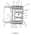
- figure 4 is a view of a gauge according to the invention comprising an ionization gauge;
- figure 5 is a block diagram of a control system suitable for use with the invention; and
- figure 6 is a block diagram of an alternative control system suitable for use with the invention.
- Referring first to figure 1, an electron
impact ionization source 1, described in detail below, comprises anelectron emitting filament 2 and a thermal-conductivity gauge filament 3 (figures 2 and 3).Ionization source 1 is fitted to asupport tube 6 by anadaptor 7, andtube 6 contains aquadrupole mass analyser 18 comprising fourelectrodes 4 supported by twoinsulators 5. Anadaptor 8 securestube 6 to ahousing 9 which is in turn attached to abase member 13 on a mountingflange 14.Flange 14 is a conventional high-vacuum type flange and is used to mount the gauge on the process chamber containing the gases to be monitored. It incorporates a vacuum tightelectrical plug 15 comprisingseveral pins 16 and acentral spigot 17 which is used to connect the electrical supplies to the gauge. Anelectron multiplier 10 and Faraday collector 11 are provided inhousing 9. - When the gauge is used as a conventional quadrupole mass spectrometer, the gas in the
process chamber 39 in which the gauge is situated is ionized insource 1 by electrons produced byfilament 2, and the ions so produced are mass analysed byquadrupole mass analyser 18. Ions emerging fromanalyser 18 strike Faraday collector 11, giving an output signal accurately proportional to the partial pressure of the gases whose ions have been selected byanalyser 18. Alternatively, ions from the analyser can be diverted intoelectron multiplier 10, which results in greater sensitivity at the expense of reproducibility and accuracy of measurement. - Referring next to figure 2,
ion chamber 12 ofsource 1 is attached toadaptor 7 by means ofscrews 19 and spaced from it by insulators 20-22. Anelectrode 23, which contains the ion exit aperture of the source, and a focusingelectrode 24 are also supported on insultors 20-22 as shown. Asupport electrode 25 carries acylindrical mesh 26 which defines the volume in which the ions are formed. Insulatingspacers 27 are fitted betweenion chamber 12 and the heads ofscrews 19, and insulatingtubes 28 are fitted over the screws as shown. - The end of
ion chamber 12 is closed byfilament support plate 29 which carrieselectron emitting filament 2 and thermal-conductivity gauge filament 3. - As shown in figure 3, each filament is fixed between filament supports 31 and 32, each of which is mounted on an
insulated feedthrough 33 inplate 29. Electrical connections to the filaments are made through barrel connectors (not shown) attached to theends 30 of thesupports filament 3 is not used.Filament 2 is maintained at a temperature at which it emits electrons so thationization source 1 functions as a conventional electron impact ionization source. - When the gauge is used as a thermal-conductivity pressure gauge, all the components of
ionization source 1, exceptfilament 3, are maintained at a fixed potential V⁻.Filament 3 is operated in the manner described below andion chamber 12 andcylindrical mesh 26 serve as heat sinks, required for the operation offilament 3 as a thermal-conductivity pressure gauge. - The
electron emitting filament 2 is identical to the filament used in a conventional electron-impact ionization source. The thermal-conductivity gauge filament 3 typically comprises a 60 mm length of 0.05mm diameter gold plated tungsten wire formed into a small diameter coil containing approximately 20 turns and about 10 mm long, fitted between filament supports 31 and 32, as shown in figure 3. - Figure 4 illustrates another preferred embodiment of the invention which comprises an ionization gauge. It is built on a
conventional vacuum flange 34 which incorporates a vacuum tightelectrical plug 35, typically fitted withpins 43 andcentral spigot 48. In a conventional application,flange 34 is bolted to asecond flange 36 which is connected toextension tube 37 onwall 38 enclosing thechamber 39.Chamber 39 is maintained substantially below atmospheric pressure.Gasket 40 is used to sealflanges bolts 41. - Filament supports 42 and 44 are connected to
pins 43 inbase 35 bytubular connectors 45.Electron emitting filament 2 is fixed to the upper end ofsupport 42 and to another ofpins 43 by means of another tubular connector. Thermal-conductivity gauge filament 3 is fixed to support 44 and one ofpins 43 in a similar fashion.Grid electrode 46, comprising a coarse spiral of thin wire, is supported on two rods (not shown), also mounted on some ofpins 43.Collector electrode 47 comprises a thin wire connected tocentral spigot 48. -
Filament 2,grid 46 andcollector electrode 47 comprise a conventional hot cathode ionization gauge and are employed as such when the gauge is used for monitoring pressures below 10⁻³ torr. For monitoring pressures greater than 10⁻³ torr,filament 3 is employed in the manner described below.Extension tube 37 andfilament support 44 act as heat sinks, as required for the operation offilament 3 as a thermal-conductivity pressure gauge. - As explained, it is only possible to incorporate thermal-conductivity gauge filaments in the gauges illstrated in figures 1-4 if they are substantially shorter than conventional thermal-conductivity gauge filaments, for example, those used in a Pirani gauge. In order to overcome the previously explained problem encountered with prior art gauges fitted with short filaments, the filaments of the invention are operated in the manner shown in figure 5.
- In figure 5, the thermal-
conductivity gauge filament 3 is connected in series with a fixedresistor 49 and a current adjusting means 50 across a stablilized voltage supply (not shown). Fixedresistor 49 is comparable to the resistance offilament 3 in its operable pressure range. The voltage appearing across resistor 49 (which is proportional to the current flowing through filament 3) is amplified by anoperational amplifier 51. The output ofamplifier 51 is applied to one input of ananalogue divider 53. - The potential appearing across
filament 3 is amplified by another operational amplifier 52 and applied to the other input ofdivider 53.Divider 53 is adapted to produce an output signal dependent on the quotient of the signals fromamplifiers 52 and 51, so that the signal applied to the input ofoperational amplifier 54 is dependent on the resistance offilament 3. The output ofamplifier 54 is applied to the adjusting means 50 so that the complete controlloop comprising amplifiers divider 53 operates to maintain constant the resistance, and therefore the temperature, offilament 3. Typically, the current adjusting means 50 comprises a power transistor. Consequently, the heat losses by conduction throughsupports Variable resistor 55 is used to apply an adjustable potential derived from a stable reference voltage Vrefto the other input ofamplifier 54, allowing the value of the resistance at which the control loop stabilizes to be adjusted, and allowing the operating temperature offilament 3 to be varied. - An output signal indicative of the pressure of
gas surrounding filament 3 is obtained by measuring the power dissipated infilament 3, which is dependent on the thermal conductivity, and therfore the pressure, of the gas. The outputs ofamplifiers 52 and 51, proportional to the voltage across the filament and the current flowing through it, respectively, are multiplied byanalogue multiplier 56. The signal at the output ofmultiplier 56 is therefore indicative of the pressure ofgas surrounding filament 3. This signal is fed tocontroller 57 and thence tooutput indicator 58, which may be a meter or a suitably programmed data acquisition system.Controller 57 also incorporates means for comparing the output of 56 with at least one predetermined signal level. If the output ofmultiplier 56 exceeds this level,controller 57 produces a trip output signal onlead 59 which disables the ionization gauge ormass spectrometer controller 60, preventing power being fed toelectron emitting filament 2.Controllers chamber 39 if the pressure deviates from an acceptable value. Further, the signal onlead 59 may be used to turn on the mass spectrometer or ionization gauge automatically when the pressure inchamber 39 has fallen to a safe value.Controller 60 may be adapted to provide a signal onlead 61 when it is operating normally, and this signal may be used to disablecontroller 57 so that interference to the operation of the mass spectrometer or ionization gauge by the electrical and magnetic fields associated withfilament 3 is prevented.Controller 60 conventionally incorporates means for turning offfilament 2 if the pressure exceeds a safe level, and a trip output 62 for controlling other equipment. - Alternatively, operational amplifier 52 can be connected across both
filament 3 andresistor 49 as shown in figure 6. The controlloop comprising amplifiers divider 53 then operates to maintain the resistance offilament 3 andresistor 49 constant, which is equivalent to maintaining the resistance offilament 3 constant becauseresistor 49 is fixed in value.Processor 63 is adapted to first subtract the signal at the output of amplifier 51 (dependent on the voltage across resistor 49) from the signal at the output of amplifier 52 (dependent on the voltage acrossresistor 49 andfilament 3 in series) and then multiply the resultant signal by the output ofamplifier 51, thereby producing an output signal proportional to the power dissipated infilament 3. Although requiring a more complicated signal processor than that required by the embodiment shown in figure 5, the figure 6 embodiment eliminates the need for operational amplifier 52 to have a high common mode rejection ratio, which is inherent in the figure 5 embodiment. - It will be appreciated that the design of electronic circuitry to implement the various conventional functions illustrated in figures 5 and 6 will present no difficulty to those skilled in the art. It will be further appreciated that alternative ways of providing the functions achieved by the arrangement of figure 5 are also possible and are within the scope of the invention. For example, the analogue signals representing the current through
filament 3 and the voltage across it may be digitized and the multiplication and division processes may then be carried out by a microprocessor. Alternatively, a look-up table which relates pressure to the values of the current and potential difference can be compiled (preferably by calibration) and stored in any suitable memory associated with the microprocessor. This eliminates the need for an analogue (or digital) multiplication process.
Claims (10)
Applications Claiming Priority (2)
| Application Number | Priority Date | Filing Date | Title |
|---|---|---|---|
| GB868603999A GB8603999D0 (en) | 1986-02-18 | 1986-02-18 | Vacuum monitoring apparatus |
| GB8603999 | 1986-02-18 |
Publications (3)
| Publication Number | Publication Date |
|---|---|
| EP0233784A2 true EP0233784A2 (en) | 1987-08-26 |
| EP0233784A3 EP0233784A3 (en) | 1989-08-02 |
| EP0233784B1 EP0233784B1 (en) | 1992-04-29 |
Family
ID=10593267
Family Applications (1)
| Application Number | Title | Priority Date | Filing Date |
|---|---|---|---|
| EP87301394A Expired - Lifetime EP0233784B1 (en) | 1986-02-18 | 1987-02-18 | Vacuum monitoring apparatus |
Country Status (4)
| Country | Link |
|---|---|
| US (1) | US4755669A (en) |
| EP (1) | EP0233784B1 (en) |
| DE (1) | DE3778565D1 (en) |
| GB (1) | GB8603999D0 (en) |
Cited By (17)
| Publication number | Priority date | Publication date | Assignee | Title |
|---|---|---|---|---|
| EP0317060A3 (en) * | 1987-09-23 | 1991-05-02 | Hewlett-Packard Company | Electron-emission filament cutoff for gc/ms systems |
| EP0658755B1 (en) * | 1993-12-15 | 1999-01-20 | Balzers Aktiengesellschaft | Procedure for evaluating the output signals of two pressure sensors, corresponding device with two sensors and pressure sensor head |
| DE19903010A1 (en) * | 1999-01-26 | 2000-08-17 | Heinz Ploechinger | Pirani pressure measuring arrangement suitable for combination sensors has first and second heating devices are insulated electrically from each other and support carries holding elements |
| DE10238961A1 (en) * | 2002-08-24 | 2004-03-04 | Pfeiffer Vacuum Gmbh | Method for operating a total pressure transmitter |
| US7155919B2 (en) | 1988-09-13 | 2007-01-02 | Brooks Automation, Inc. | Cryopump temperature control of arrays |
| US7413411B2 (en) | 1993-07-16 | 2008-08-19 | Brooks Automation, Inc. | Electronically controlled vacuum pump |
| WO2019229465A1 (en) * | 2018-05-31 | 2019-12-05 | Micromass Uk Limited | Bench-top time of flight mass spectrometer |
| US11355331B2 (en) | 2018-05-31 | 2022-06-07 | Micromass Uk Limited | Mass spectrometer |
| US11367607B2 (en) | 2018-05-31 | 2022-06-21 | Micromass Uk Limited | Mass spectrometer |
| US11373849B2 (en) | 2018-05-31 | 2022-06-28 | Micromass Uk Limited | Mass spectrometer having fragmentation region |
| US11437226B2 (en) | 2018-05-31 | 2022-09-06 | Micromass Uk Limited | Bench-top time of flight mass spectrometer |
| US11476103B2 (en) | 2018-05-31 | 2022-10-18 | Micromass Uk Limited | Bench-top time of flight mass spectrometer |
| US11538676B2 (en) | 2018-05-31 | 2022-12-27 | Micromass Uk Limited | Mass spectrometer |
| US11621154B2 (en) | 2018-05-31 | 2023-04-04 | Micromass Uk Limited | Bench-top time of flight mass spectrometer |
| US11879470B2 (en) | 2018-05-31 | 2024-01-23 | Micromass Uk Limited | Bench-top time of flight mass spectrometer |
| US12009193B2 (en) | 2018-05-31 | 2024-06-11 | Micromass Uk Limited | Bench-top Time of Flight mass spectrometer |
| US12027359B2 (en) | 2018-05-31 | 2024-07-02 | Micromass Uk Limited | Bench-top Time of Flight mass spectrometer |
Families Citing this family (16)
| Publication number | Priority date | Publication date | Assignee | Title |
|---|---|---|---|---|
| JP2735222B2 (en) * | 1988-06-01 | 1998-04-02 | 株式会社日立製作所 | Mass spectrometer |
| US5256874A (en) * | 1992-03-25 | 1993-10-26 | California Institute Of Technology | Gridded electron reversal ionizer |
| US5455239A (en) * | 1993-08-05 | 1995-10-03 | Merck & Co. Inc. | 3-aryl of heteroaryl-7-heteroaralkylamido cephalosporin compounds, compositions and methods of use |
| GB9409953D0 (en) * | 1994-05-17 | 1994-07-06 | Fisons Plc | Mass spectrometer and electron impact ion source therefor |
| US6566884B2 (en) * | 2001-09-13 | 2003-05-20 | Duniway Stockroom Corporation | Ionization vacuum pressure gauge |
| US6955073B2 (en) * | 2002-10-16 | 2005-10-18 | Alcon, Inc. | Pressure sensing in surgical console |
| US6868720B2 (en) * | 2002-10-16 | 2005-03-22 | Alcon, Inc. | Testing of pressure sensor in surgical cassette |
| US6941813B2 (en) * | 2003-06-30 | 2005-09-13 | Alcon, Inc. | Noninvasive pressure sensing assembly |
| US7313966B2 (en) * | 2004-12-14 | 2008-01-01 | Brooks Automation, Inc. | Method and apparatus for storing vacuum gauge calibration parameters and measurement data on a vacuum gauge structure |
| US7207224B2 (en) * | 2005-06-10 | 2007-04-24 | Brooks Automation, Inc. | Wide-range combination vacuum gauge |
| US7418869B2 (en) * | 2005-06-10 | 2008-09-02 | Brooks Automation, Inc. | Wide-range combination vacuum gauge |
| US7613586B2 (en) * | 2007-01-16 | 2009-11-03 | Honeywell International Inc. | Thermal vacuum gauge |
| JP5103983B2 (en) * | 2007-03-28 | 2012-12-19 | 東京エレクトロン株式会社 | Gas supply method, gas supply apparatus, semiconductor manufacturing apparatus, and storage medium |
| WO2012030595A2 (en) | 2010-08-30 | 2012-03-08 | Alcon Research, Ltd. | Optical sensing system including electronically switched optical magnification |
| US10845263B2 (en) | 2018-04-17 | 2020-11-24 | Mks Instruments, Inc. | Thermal conductivity gauge |
| US12123794B2 (en) | 2022-10-11 | 2024-10-22 | Mks Instruments, Inc. | Pirani gauge with model of power dissipation |
Family Cites Families (13)
| Publication number | Priority date | Publication date | Assignee | Title |
|---|---|---|---|---|
| US2758233A (en) * | 1951-09-12 | 1956-08-07 | Gen Electric | Electric discharge device for gas pressure determination |
| US2800796A (en) * | 1952-08-05 | 1957-07-30 | Trans Souics Inc | Pressure measuring device |
| US3267326A (en) * | 1963-09-05 | 1966-08-16 | Varian Associates | Vacuum gauge |
| US3319117A (en) * | 1964-03-24 | 1967-05-09 | Varian Associates | Ionization vacuum gauge for use in the 10-6 to 1 torr range |
| DE1473370A1 (en) * | 1964-09-04 | 1968-11-07 | Bbc Brown Boveri & Cie | Procedure for vacuum measurement |
| US3361340A (en) * | 1965-10-18 | 1968-01-02 | Cons Vacuum Corp | High vacuum pumping system |
| US3576465A (en) * | 1968-04-01 | 1971-04-27 | Norton Co | Ionization gauge control with emission responsive control of thermionic filament heating |
| US3723729A (en) * | 1971-02-02 | 1973-03-27 | Hewlett Packard Co | Ionization chamber for use with a mass spectrometer |
| US3761708A (en) * | 1971-10-08 | 1973-09-25 | Us Interior | Electron suppressor grid for a mass spectrometer |
| US4035720A (en) * | 1975-12-31 | 1977-07-12 | Harvey Philip C | Ion gauge system |
| US4251725A (en) * | 1979-08-06 | 1981-02-17 | Honeywell Inc. | Programmed sample pyrolysis for mass spectrometer |
| US4314205A (en) * | 1979-11-19 | 1982-02-02 | Paitich Ronald M | Method and means for vacuum gauging |
| GB8305228D0 (en) * | 1983-02-25 | 1983-03-30 | Vg Instr Ltd | Operating quadrupole mass spectrometers |
-
1986
- 1986-02-18 GB GB868603999A patent/GB8603999D0/en active Pending
-
1987
- 1987-02-18 DE DE8787301394T patent/DE3778565D1/en not_active Expired - Lifetime
- 1987-02-18 US US07/016,014 patent/US4755669A/en not_active Expired - Fee Related
- 1987-02-18 EP EP87301394A patent/EP0233784B1/en not_active Expired - Lifetime
Cited By (18)
| Publication number | Priority date | Publication date | Assignee | Title |
|---|---|---|---|---|
| EP0317060A3 (en) * | 1987-09-23 | 1991-05-02 | Hewlett-Packard Company | Electron-emission filament cutoff for gc/ms systems |
| US7155919B2 (en) | 1988-09-13 | 2007-01-02 | Brooks Automation, Inc. | Cryopump temperature control of arrays |
| US7413411B2 (en) | 1993-07-16 | 2008-08-19 | Brooks Automation, Inc. | Electronically controlled vacuum pump |
| EP0658755B1 (en) * | 1993-12-15 | 1999-01-20 | Balzers Aktiengesellschaft | Procedure for evaluating the output signals of two pressure sensors, corresponding device with two sensors and pressure sensor head |
| DE19903010A1 (en) * | 1999-01-26 | 2000-08-17 | Heinz Ploechinger | Pirani pressure measuring arrangement suitable for combination sensors has first and second heating devices are insulated electrically from each other and support carries holding elements |
| DE19903010B4 (en) * | 1999-01-26 | 2004-07-08 | Plöchinger, Heinz, Dipl.-Ing. | Pirani pressure measuring arrangement and combination sensor with such a Pirani pressure measuring arrangement |
| DE10238961A1 (en) * | 2002-08-24 | 2004-03-04 | Pfeiffer Vacuum Gmbh | Method for operating a total pressure transmitter |
| US11355331B2 (en) | 2018-05-31 | 2022-06-07 | Micromass Uk Limited | Mass spectrometer |
| WO2019229465A1 (en) * | 2018-05-31 | 2019-12-05 | Micromass Uk Limited | Bench-top time of flight mass spectrometer |
| US11367607B2 (en) | 2018-05-31 | 2022-06-21 | Micromass Uk Limited | Mass spectrometer |
| US11373849B2 (en) | 2018-05-31 | 2022-06-28 | Micromass Uk Limited | Mass spectrometer having fragmentation region |
| US11437226B2 (en) | 2018-05-31 | 2022-09-06 | Micromass Uk Limited | Bench-top time of flight mass spectrometer |
| US11476103B2 (en) | 2018-05-31 | 2022-10-18 | Micromass Uk Limited | Bench-top time of flight mass spectrometer |
| US11538676B2 (en) | 2018-05-31 | 2022-12-27 | Micromass Uk Limited | Mass spectrometer |
| US11621154B2 (en) | 2018-05-31 | 2023-04-04 | Micromass Uk Limited | Bench-top time of flight mass spectrometer |
| US11879470B2 (en) | 2018-05-31 | 2024-01-23 | Micromass Uk Limited | Bench-top time of flight mass spectrometer |
| US12009193B2 (en) | 2018-05-31 | 2024-06-11 | Micromass Uk Limited | Bench-top Time of Flight mass spectrometer |
| US12027359B2 (en) | 2018-05-31 | 2024-07-02 | Micromass Uk Limited | Bench-top Time of Flight mass spectrometer |
Also Published As
| Publication number | Publication date |
|---|---|
| EP0233784A3 (en) | 1989-08-02 |
| GB8603999D0 (en) | 1986-03-26 |
| EP0233784B1 (en) | 1992-04-29 |
| US4755669A (en) | 1988-07-05 |
| DE3778565D1 (en) | 1992-06-04 |
Similar Documents
| Publication | Publication Date | Title |
|---|---|---|
| EP0233784B1 (en) | Vacuum monitoring apparatus | |
| US5273610A (en) | Apparatus and method for determining power in plasma processing | |
| US5422573A (en) | Ionization gauge and method of using and calibrating same | |
| US5296817A (en) | Ionization gauge and method of using and calibrating same | |
| US12181366B2 (en) | Thermal conductivity gauge | |
| US5250906A (en) | Ionization gauge and method of using and calibrating same | |
| US6619131B2 (en) | Combination pressure sensor with capacitive and thermal elements | |
| US4967157A (en) | Method and circuit for extending the range of a cold cathode discharge vacuum gauge | |
| US3353048A (en) | Ionization gauge for monitoring the flow of evaporant material | |
| US4093913A (en) | Vacuum measuring ionization apparatus control | |
| Littauer | An Ion Current Integrator | |
| Derenbach et al. | Setup for angle-resolved electron spectrometry using monochromatised synchrotron radiation | |
| Conn et al. | Cold cathode ionisation gauges for the measurement of low pressures | |
| Mao et al. | Residual gas analysers and their use in high vacuum systems | |
| US3399341A (en) | Vacuum pressure measurement apparatus utlizing hollow cathode discharge | |
| US3622870A (en) | Penning gauge circuit improvement | |
| Picard et al. | A Reliable High Vacuum Gauge and Control System | |
| Jousten | Pressure measurement with ionization gauges | |
| Sellenger | A review of vacuum gauges and methods for high vacuum gauge calibration | |
| JPH0743236A (en) | Constant current field emission vacuum gauge | |
| US20070170926A1 (en) | Method and device for measuring ultrahigh vacuum | |
| US3227947A (en) | Ionization vacuum meter with switching means for linear and logarithmic responses | |
| Nash | The use of hot filament ionization gauges | |
| KR950006307B1 (en) | Bayeard Alpert Hot Cathode Vacuum System | |
| Groβe-Bley | A hot cathode ionization gauge transmitter for industrial vacuum measurement |
Legal Events
| Date | Code | Title | Description |
|---|---|---|---|
| PUAI | Public reference made under article 153(3) epc to a published international application that has entered the european phase |
Free format text: ORIGINAL CODE: 0009012 |
|
| AK | Designated contracting states |
Kind code of ref document: A2 Designated state(s): CH DE FR GB LI NL |
|
| PUAL | Search report despatched |
Free format text: ORIGINAL CODE: 0009013 |
|
| AK | Designated contracting states |
Kind code of ref document: A3 Designated state(s): CH DE FR GB LI NL |
|
| 17P | Request for examination filed |
Effective date: 19891117 |
|
| 17Q | First examination report despatched |
Effective date: 19901017 |
|
| RAP1 | Party data changed (applicant data changed or rights of an application transferred) |
Owner name: VG INSTRUMENTS GROUP LIMITED |
|
| GRAA | (expected) grant |
Free format text: ORIGINAL CODE: 0009210 |
|
| AK | Designated contracting states |
Kind code of ref document: B1 Designated state(s): CH DE FR GB LI NL |
|
| PG25 | Lapsed in a contracting state [announced via postgrant information from national office to epo] |
Ref country code: NL Effective date: 19920429 |
|
| REF | Corresponds to: |
Ref document number: 3778565 Country of ref document: DE Date of ref document: 19920604 |
|
| ET | Fr: translation filed | ||
| RAP2 | Party data changed (patent owner data changed or rights of a patent transferred) |
Owner name: FISONS PLC |
|
| NLV1 | Nl: lapsed or annulled due to failure to fulfill the requirements of art. 29p and 29m of the patents act | ||
| REG | Reference to a national code |
Ref country code: GB Ref legal event code: 732 |
|
| REG | Reference to a national code |
Ref country code: CH Ref legal event code: PUE Owner name: FISONS PLC |
|
| REG | Reference to a national code |
Ref country code: FR Ref legal event code: TP |
|
| PGFP | Annual fee paid to national office [announced via postgrant information from national office to epo] |
Ref country code: FR Payment date: 19930126 Year of fee payment: 7 |
|
| PGFP | Annual fee paid to national office [announced via postgrant information from national office to epo] |
Ref country code: DE Payment date: 19930211 Year of fee payment: 7 |
|
| PGFP | Annual fee paid to national office [announced via postgrant information from national office to epo] |
Ref country code: GB Payment date: 19930212 Year of fee payment: 7 |
|
| PGFP | Annual fee paid to national office [announced via postgrant information from national office to epo] |
Ref country code: CH Payment date: 19930218 Year of fee payment: 7 |
|
| PLBE | No opposition filed within time limit |
Free format text: ORIGINAL CODE: 0009261 |
|
| STAA | Information on the status of an ep patent application or granted ep patent |
Free format text: STATUS: NO OPPOSITION FILED WITHIN TIME LIMIT |
|
| 26N | No opposition filed | ||
| PG25 | Lapsed in a contracting state [announced via postgrant information from national office to epo] |
Ref country code: GB Effective date: 19940218 |
|
| PG25 | Lapsed in a contracting state [announced via postgrant information from national office to epo] |
Ref country code: LI Effective date: 19940228 Ref country code: CH Effective date: 19940228 |
|
| GBPC | Gb: european patent ceased through non-payment of renewal fee |
Effective date: 19940218 |
|
| PG25 | Lapsed in a contracting state [announced via postgrant information from national office to epo] |
Ref country code: FR Effective date: 19941031 |
|
| REG | Reference to a national code |
Ref country code: CH Ref legal event code: PL |
|
| PG25 | Lapsed in a contracting state [announced via postgrant information from national office to epo] |
Ref country code: DE Effective date: 19941101 |
|
| REG | Reference to a national code |
Ref country code: FR Ref legal event code: ST |