EP0233408B1 - Viskositätsmessgerät - Google Patents
Viskositätsmessgerät Download PDFInfo
- Publication number
- EP0233408B1 EP0233408B1 EP86309694A EP86309694A EP0233408B1 EP 0233408 B1 EP0233408 B1 EP 0233408B1 EP 86309694 A EP86309694 A EP 86309694A EP 86309694 A EP86309694 A EP 86309694A EP 0233408 B1 EP0233408 B1 EP 0233408B1
- Authority
- EP
- European Patent Office
- Prior art keywords
- sample
- support column
- sample container
- temperature probe
- sensor elements
- Prior art date
- Legal status (The legal status is an assumption and is not a legal conclusion. Google has not performed a legal analysis and makes no representation as to the accuracy of the status listed.)
- Expired - Lifetime
Links
- 239000000523 sample Substances 0.000 claims description 73
- 230000005484 gravity Effects 0.000 claims description 3
- 238000006073 displacement reaction Methods 0.000 description 11
- 238000005259 measurement Methods 0.000 description 5
- 238000006243 chemical reaction Methods 0.000 description 4
- WABPQHHGFIMREM-UHFFFAOYSA-N lead(0) Chemical compound [Pb] WABPQHHGFIMREM-UHFFFAOYSA-N 0.000 description 3
- 239000012086 standard solution Substances 0.000 description 3
- 229910000639 Spring steel Inorganic materials 0.000 description 2
- 239000007788 liquid Substances 0.000 description 2
- 239000000463 material Substances 0.000 description 2
- BASFCYQUMIYNBI-UHFFFAOYSA-N platinum Chemical compound [Pt] BASFCYQUMIYNBI-UHFFFAOYSA-N 0.000 description 2
- XAGFODPZIPBFFR-UHFFFAOYSA-N aluminium Chemical compound [Al] XAGFODPZIPBFFR-UHFFFAOYSA-N 0.000 description 1
- 229910052782 aluminium Inorganic materials 0.000 description 1
- 239000004411 aluminium Substances 0.000 description 1
- 230000000712 assembly Effects 0.000 description 1
- 238000000429 assembly Methods 0.000 description 1
- 239000011521 glass Substances 0.000 description 1
- 230000003287 optical effect Effects 0.000 description 1
- 229910052697 platinum Inorganic materials 0.000 description 1
- 229910001220 stainless steel Inorganic materials 0.000 description 1
- 239000010935 stainless steel Substances 0.000 description 1
- 239000000126 substance Substances 0.000 description 1
- 229920003002 synthetic resin Polymers 0.000 description 1
- 239000000057 synthetic resin Substances 0.000 description 1
Images
Classifications
-
- G—PHYSICS
- G01—MEASURING; TESTING
- G01N—INVESTIGATING OR ANALYSING MATERIALS BY DETERMINING THEIR CHEMICAL OR PHYSICAL PROPERTIES
- G01N11/00—Investigating flow properties of materials, e.g. viscosity, plasticity; Analysing materials by determining flow properties
- G01N11/10—Investigating flow properties of materials, e.g. viscosity, plasticity; Analysing materials by determining flow properties by moving a body within the material
- G01N11/16—Investigating flow properties of materials, e.g. viscosity, plasticity; Analysing materials by determining flow properties by moving a body within the material by measuring damping effect upon oscillatory body
Definitions
- the present invention relates to a viscosity measuring apparatus, and more particularly, to a vibration-type viscosity measuring apparatus for measuring the viscosity of a sample by determining the amplitude of vibration of a tuning fork-like member in the sample.
- JP-A-59-107236 proposes viscosity measuring apparatus having a pair of vibrating members which are driven in inverse phase relation to each other. By this means the pair of vibrating members can be in a resonance state, and therefore the reaction of the support section due to the vibrations is little or can be reduced to a negligible degree, resulting in substantial improvement in the accuracy of the measurement.
- JP-A-59-107236 Various disadvantages have however been encountered with the apparatus of JP-A-59-107236. Firstly it is to be noted that the viscosity of a liquid is dependant on temperature, however JP-A-59-107236 makes no provision for the determination of the temperature of a sample. Furthermore, in order to avoid inaccuracies in the measurement of the viscosity, the vibrating members must extend into the sample an exact distance. In the past this has presented certain difficulties since it has often been necessary to measure carefully the amount of sample used to ensure that the vibrating members extend into the sample for the correct depth.
- viscosity measuring apparatus comprising, a pair of vibrating means each having at a free end a sensor element adapted to be inserted into a sample to be measured, means for driving said pair of vibrating means at the same frequency and in reverse phase relation to each other, a detector for detecting the amplitude of vibration of at least one of said pair of vibrating means, said amplitude varying in response to the viscosity of the sample, and a temperature probe provided at an intermediate point between said sensor elements whereby the viscosity and the temperature of the sample can be measured simultaneously.
- a tuning fork vibration-type viscosity measuring apparatus equipped with a thermometer so that the apparatus is capable of measuring continuously both the viscosity and the temperature of the sample quickly and accurately to determine the relative relation between the viscosity and the temperature of the sample.
- the apparatus comprises a support block fixed to a base frame and has a support column extending downwardly, said vibrating means being fixed to said support block on opposite sides thereof and extending downwardly therefrom, and said temperature probe being secured to the lower end of said support column, said sensor elements and said temperature probe being arranged in the same vertical plane.
- a carrier apparatus that carries a sample container is mounted at the lower end section of the support column, the sample container is attached detachably to the carrier apparatus, and the carrier apparatus is mounted slidably axially of the support column in such a way that the sample container can be moved vertically with respect to the support column.
- the support column preferably has level indicating pins extending downward from the end section of the support column, and the carrier apparatus includes means for adjusting the height of the carrier apparatus in the axial direction of the support column so that the ends of the indicating pins may be in registry with the surface of the sample in the sample container.
- the vibrating members and the thermometer can be inserted into the sample, and the inserted lengths of the pair of vibration members and the thermometer in the sample can be simultaneously adjusted.
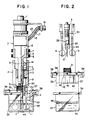
- Fig. 1 is a partial cut-away side elevational view of a viscosity measuring apparatus according to an embodiment of the present invention
- Fig. 2 is an exploded side elevational view of the carrier apparatus shown in Fig. 1;
- Fig. 3 is a side elevational view of the vibrator subassembly shown in Fig. 1;
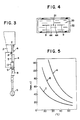
- Fig. 4 is a plan view illustrating the relative positional relation of the sensor plates the thermometer and the level indicating pins in the sample container;
- Fig 5 is a graph illustrating the relation between the viscosity and the temperature of three samples.
- a vibration-type viscosity measuring apparatus is provided with a hollow support block 2 of a rigid material firmly fixed to a frame shaft 1 extending from a base (not shown), the support block 2 having a support column 3 extending downward.
- a pair of vibrating means in the form of vibrator subassemblies 4 comprising a tuning fork-like vibrator are fixed to the lower end section of the support block 2 and extend downward from the support block 2 with the vibrator subassemblies 4 positioned on opposite sides of the support column 3.
- Each of the vibrator subassemblies 4 includes a leaf spring 5 one end of which is fixed to the support block 2 by screws 6 via a fastener 7, an intermediate plate 8 firmly attached to the other end of the leaf spring 5 and a sensor plate 9 fixed to one end of the intermediate plate 8 by screws 10.
- the leaf spring 5 is advantageously made of an identity elastic spring steel and the intermediate plate 8 is preferably made of a relatively rigid light material such as aluminium.
- the sensor plate 9 is a very thin plate having a thickness of the order of 0.2 mm that may be made of a chemical-resistant stainless steel, and the free end of the sensor plate is in the shape of a disk 11 having a diameter of the order, for example, of 20 mm.
- the vibrator subassemblies 4 are arranged symmetrically relative to each other and each of the vibrator subassemblies 4 has above the intermediate plate 8 an electromagnetic coil 12 and a permanent magnet 13 cooperative therewith that are attached to the support column 3 and intermediate plate 8 respectively.
- Each combination of electromagnetic coil 12 and permanent magnet 13 serves as a driving apparatus for vibrating the corresponding vibrator subassembly 4, so that the vibrator subassemblies 4 can be vibrated at the same frequency in reverse phase relation to each other, that is, with a phase difference of 180 degrees.
- the driving frequency is 30 Hz
- the single amplitude is 20 microns under no load at the point where a displacement sensor 14 that will be described hereinafter is attached.
- the sensor plates 9 arranged in a pair are situated in the same imaginary vertical plane, and as a result the torsional reaction of the support block 2 that would be induced when they are situated in different vertical planes can be obviated.
- the electromagnet coil 12 be situated on the side of the support column 3 as in the illustrated embodiment, since a lead wire 12 of the coil 15 can be led through the support column 3 to a terminal fitment 16 (situated upward).
- the viscosity measuring apparatus is a small-sized one for measuring a sample having a low viscosity, instead of the electromagnetic driving apparatus shown a piezo-electric driving apparatus can be employed.
- a displacement detector 14 is provided to the support column 3 between the support block 2 and the electomagnetic coil 12 and is opposed to the leaf spring 5 of the vibrator subassembly 4, the displacement detector 14 converts the amplitude of one of the vibrator assemblies 4 to an electrical signal.
- an additional displacement detector may be provided for the other vibrator subassembly, since both the vibrator subassemblies 4 give substantially the same amplitude, only one displacement detector is required.
- the amplitude of the vibrator subassemblies 14 is influenced by the change in the viscosity resistance thereof, and this amplitude is detected electrically by the displacement detector 14, and the viscosity of the sample can be calculated from the detected amplitude in a known manner.
- the displacement detector 14 may be, for example, of a known non-contacting eddy current loss type, and if this known displacement detector is used, the leaf spring 5 opposed thereto is made of a magnetic spring steel. Instead of the eddy current loss type displacement sensor a known optical displacement sensor can also be used.
- a lead wire 17 of the displacement detector 14 is also led to the common terminal fitment 16 through the support column 3.
- the center of gravity G of the vibrator subassembly 4 is positioned on the vibration center line Z-Z of the leaf spring 5, and in this manner the vertical component of force that would result from the reaction of the vibrations of the vibrator subassembly 4 can be prevented from occurring or can be minimized to a substantially negligible extent.
- the leaf spring 5 is attached at a right angle to the support block 2, and when the leaf spring 5 is attached, it is suggested that the attaching surface of the support block 2 should be made smooth and high tensile bolts used.
- thermometer indicated generally at 20 is attached to the lower end of the support column 3 and a sheathed probe 21 of the thermometer 20 extends downward.
- the temperature probe 21 is situated at an intermediate position between the sensor plates 9 arranged in a pair and is also situated in the same imaginary vertical plane as the sensor plates 9, and the lower end of the temperature probe 21 is situated generally in the same imaginary vertical plane as that where the sensor plates 9 are situated. Since the temperature probe 21 is arranged in the same imaginary vertical plane as that where the pair of sensor plates 9 is situated, a turblent flow of the sample due to the presence of the temperature probe 21 between the sensor plates can be prevented from occurring.
- the thermometer 20 may be a known thermometer having a platinum resistance temperature detector in a sheath, and this known thermometer has a circuit unit 22 including an amplifier at the base end of the sheath. A lead wire 23 of the circuit unit 22 is led to the common terminal fitment 16 through the support column 3.
- the lower end section of the support column 3 is formed with a male thread 30, and a carrier apparatus 32 having an adjusting nut member 31 threadably engageable with the male thread 30 is attached to the support column 3.
- the carrier apparatus 32 carries a sample container 33 detachably and serves as a lid for closing the open surface of the sample container 33.
- the sample container 33 is advantageously made of a transparent glass as in the case of a beaker, has a flange 34 around the opening periphery thereof, and is formed with indications 36 comprising two parallel lines for indicating the allowable volume of the sample 35 to be introduced into the container 33.
- the carrier apparatus 32 includes a lid member 37 for example of a synthetic resin of excellent heat insulating property that has dimensions such that it snuggly fits onto the sample container 33, and the lid member 37 has flanges 38.
- the lid member 37 is provided with a pair of known clamp fitments 39, and when the clamp fitments 39 are engaged with the flange 34 of the sample container 33, the sample container 33 can be attached to the carrier apparatus 32.
- the adjusting nut member 31 threadably engaged with the male thread 30 is supported rotatably relative to the lid member 37, the nut member 31 has a stopper 40 at its lower end, so that the axial movement of the nut member 31 is restricted by the stopper 40.
- the lid member 37 is formed with a pair of thin slits 42, preventing heat from diffusing, through which the pair of sensor plates 9 can be passed.
- the carrier apparatus 32 is mounted to the lower end section of the support column 3, and the sample container 33 is attached detachably to the carrier apparatus 32.
- Two pins 44 are fixed to the lower end of the support column 3 to extend downward, are positioned as shown in Fig. 4 on opposite sides of the temperature probe 21 and between the probe 21 and the sensor plates 9, and are arranged in the same imaginary vertical plane as the sensor plates 9 and the temperature probe 21.
- the tips of the pins 44 have a role as an indicator for indicating a desired surface level of the sample 35 in the container 33 so that the height of the sample container 33 relative to the support column 3 can be determined.
- the adjusting nut member 31 of the carrier apparatus 32 is rotated to move the sample container 33 together with the carrier apparatus 32 axially with respect to the support column 3, thereby eliminating such non-registration.
- a troublesome operation for introducing a precisely determined amount of a sample into the sample container 33 would not be required, and if different amounts of a sample within the allowable range between the two indication lines 36 marked on the sample container 3 are introduced, the sensor plates 9 and the temperature probe 21 can be inserted for definite lengths into the sample at all times so that an error of measurement due to a difference between the inserted depths of them can be prevented.
- Fig. 6 is a graph showing the results of measurements of three known calibration standard solutions A, B and C by using a viscosity measuring apparatus produced in accordance with the present invention, in which the measured viscosities (in mPa.S) are plotted as ordinate and the temperatures (in °C) are plotted as abscissa.
- the above standard solutions A, B and C are types JS200, JS100 and JS50 defined in Japanese Industrial Standards, and after these standard solutions are heated to 60°C, they are measured while they are allowed to cool spontaneously.
- a viscosity measuring apparatus can be provided that can be used for measuring liquids having a viscosity in the range of from 1 mPa.S to 100 Pa.S.
Landscapes
- General Health & Medical Sciences (AREA)
- Physics & Mathematics (AREA)
- Life Sciences & Earth Sciences (AREA)
- Chemical & Material Sciences (AREA)
- Analytical Chemistry (AREA)
- Biochemistry (AREA)
- Health & Medical Sciences (AREA)
- General Physics & Mathematics (AREA)
- Immunology (AREA)
- Pathology (AREA)
- Investigating Or Analyzing Materials Using Thermal Means (AREA)
- Investigating Or Analysing Biological Materials (AREA)
- Sampling And Sample Adjustment (AREA)
- Measurement Of Mechanical Vibrations Or Ultrasonic Waves (AREA)
Claims (9)
- Viskositätsmeßvorrichtung umfassend ein Paar von VibrierEinrichtungen (4), welche jeweils an ihren freien Enden zum Einführen in eine zu messende Probe (35) vorgesehene SensorElemente (9) aufweisen, Einrichtungen (12,13) zum Antrieb des Paares von Vibrier-Einrichtungen (4) mit der selben Frequenz und in umgekehrter Phasenbeziehung zueinander, einen Detektor (14) zum Erfassen der Amplitude der Schwingung wenigstens einer des Paars von Vibrier-Einrichtungen (4), wobei sich die Amplitude in Abhängigkeit von der Viskosität der Probe (35) ändert, und einen an einem Zwischenpunkt zwischen den SensorElementen (9) vorgesehenen Temperaturfühler (21), wodurch die Viskosität und die Temperatur der Probe (35) gleichzeitig gemessen werden können.
- Vorrichtung nach Anspruch 1, umfassend einen Halterungsblock (2), welcher an einem Grundrahmen (1) befestigt ist und eine sich davon nach unten erstreckende Halterungssäule (3) aufweist, worin die Vibrier-Einrichtungen (4) an dem Halterungsblock (2) an gegenüberliegenden Seiten davon befestigt sind und sich davon nach unten erstrecken und worin der Temperaturfühler (21) an dem unteren Ende der Halterungssäule (3) angebracht ist, wobei die Sensor-Elemente (9) und der Temperaturfühler (21) in der selben vertikal verlaufenden Ebene angeordnet sind.
- Vorrichtung nach Anspruch 2, weiter einschließend: einen Probenbehälter (33) zur Aufnahme der zu messenden Probe (35) und eine Einrichtung (31) zum Einstellen des Relativabstands zwischen dem Halterungsblock (2) und dem Probenbehälter (33), wodurch die Eintauch-Tiefe der Sensor-Elemente (9) und des Temperaturfühlers (21) in einer in dem Probenbehälter befindlichen Probe kontrolliert werden kann.
- Vorrichtung nach Anspruch 3, worin die EinstellEinrichtung (31) eine am unteren Ende der Halterungssäule (3) axial zu der Halterungssäule (3) bewegbar befestigte Trägereinrichtung (32) einschließt, wobei die Trägereinrichtung (32) zum lösbaren Tragen des Probenbehälters (33) vorgesehen ist, wodurch der Probenbehälter (33) zusammen mit der Trägereinrichtung (32) axial zu der Halterungssäule (3) bewegt werden kann.
- Vorrichtung nach Anspruch 4, worin die Trägereinrichtung (32) mit einem Deckelglied (37) des Probenbehälters und mit einem drehbar an dem Deckelglied (37) gehalterten Einstellmutter-Glied (31) versehen ist, wobei das Mutterglied (31) einen axialen Stopper (40) aufweist und mit einem an dem unteren Endabschnitt der Halterungssäule (3) ausgebildeten Außengewinde (30) in Gewinde-Eingriff gebracht werden kann, wodurch das Einstellmutter-Glied (31) axial zu der Halterungssäule (3) bewegt werden kann, und worin die Trägereinrichtung (32) weiter mit an dem Deckelglied (37) vorgesehenen Klemm-Einrichtungen (39) zum Tragen des Probenbehälters (33) versehen ist.
- Vorrichtung nach einem der Ansprüche 3 bis 5, worin die Vorrichtung weiter eine Einrichtung (44) einschließt zum Anzeigen der Position des Oberflächenpegels der in dem Probenbehälter (33) befindlichen Probe (35), um den wünschenswerten Relativabstand zwischen dem Halterungsblock (2) und dem Probenbehälter (33) zu zeigen.
- Vorrichtung nach Anspruch 6, worin die Anzeige-Einrichtung (44) zwei sich von dem unteren Ende der Halterungssäule (3) nach unten erstreckende Stifte umfaßt, wobei die Stifte zwischen den Sensor-Elementen und dem Temperaturfühler (21) in der vertikalen Ebene liegen, in der die Sensor-Elemente (9) und der Temperaturfühler (21) gelegen sind.
- Vorrichtung nach einem der vorhergehenden Ansprüche, worin jede der Vibrier-Einrichtungen (4) derart angeordnet ist, daß der Schwerpunkt der Vibrier-Einrichtung (4) auf der Mittellinie der Schwingung angeordnet ist.
- Vorrichtung nach einem der Ansprüche 2 bis 8, worin die Vibrier-Einrichtungen (4) an einer gleichmäßigen Fläche des Halterungsblocks (2) mit hoch zugfesten Bolzen befestigt sind.
Applications Claiming Priority (2)
| Application Number | Priority Date | Filing Date | Title |
|---|---|---|---|
| JP277939/85 | 1985-12-12 | ||
| JP60277939A JPS62137537A (ja) | 1985-12-12 | 1985-12-12 | 粘度測定装置の試料温度測定装置 |
Publications (3)
| Publication Number | Publication Date |
|---|---|
| EP0233408A2 EP0233408A2 (de) | 1987-08-26 |
| EP0233408A3 EP0233408A3 (en) | 1989-01-11 |
| EP0233408B1 true EP0233408B1 (de) | 1991-04-03 |
Family
ID=17590386
Family Applications (1)
| Application Number | Title | Priority Date | Filing Date |
|---|---|---|---|
| EP86309694A Expired - Lifetime EP0233408B1 (de) | 1985-12-12 | 1986-12-12 | Viskositätsmessgerät |
Country Status (7)
| Country | Link |
|---|---|
| US (1) | US4729237A (de) |
| EP (1) | EP0233408B1 (de) |
| JP (1) | JPS62137537A (de) |
| KR (1) | KR890001980B1 (de) |
| CN (1) | CN1012107B (de) |
| CA (1) | CA1282252C (de) |
| DE (2) | DE3678559D1 (de) |
Cited By (1)
| Publication number | Priority date | Publication date | Assignee | Title |
|---|---|---|---|---|
| CN104736994A (zh) * | 2012-09-27 | 2015-06-24 | 高准公司 | 获得在参考温度下的流动流体粘度的仪表电子设备和方法 |
Families Citing this family (28)
| Publication number | Priority date | Publication date | Assignee | Title |
|---|---|---|---|---|
| JPH01132931A (ja) * | 1987-11-18 | 1989-05-25 | Chichibu Cement Co Ltd | 粘度計による試料の物性解析方法 |
| US4993480A (en) * | 1989-02-01 | 1991-02-19 | Chichibu Cement Kabushiki Kaisha | Temperature controlling means for a thermostat for use in measuring viscosity |
| EP0934515B1 (de) | 1996-10-09 | 2006-03-08 | Symyx Technologies, Inc. | Infrarot-spektroskopie und abbildung von bibliotheken |
| US6494079B1 (en) | 2001-03-07 | 2002-12-17 | Symyx Technologies, Inc. | Method and apparatus for characterizing materials by using a mechanical resonator |
| US6393895B1 (en) | 1997-10-08 | 2002-05-28 | Symyx Technologies, Inc. | Method and apparatus for characterizing materials by using a mechanical resonator |
| JP3298898B2 (ja) * | 1997-12-26 | 2002-07-08 | 日本碍子株式会社 | 双頭型質量センサおよびその質量検出方法 |
| US6311549B1 (en) | 1999-09-23 | 2001-11-06 | U T Battelle Llc | Micromechanical transient sensor for measuring viscosity and density of a fluid |
| WO2002093126A2 (en) * | 2001-05-15 | 2002-11-21 | Baker Hughes Incorporated | Method and apparatus for downhole fluid characterization using flxural mechanical resonators |
| US7317989B2 (en) * | 2001-05-15 | 2008-01-08 | Baker Hughes Incorporated | Method and apparatus for chemometric estimations of fluid density, viscosity, dielectric constant, and resistivity from mechanical resonator data |
| US7162918B2 (en) * | 2001-05-15 | 2007-01-16 | Baker Hughes Incorporated | Method and apparatus for downhole fluid characterization using flexural mechanical resonators |
| US7302830B2 (en) | 2001-06-06 | 2007-12-04 | Symyx Technologies, Inc. | Flow detectors having mechanical oscillators, and use thereof in flow characterization systems |
| WO2004036207A2 (en) * | 2002-10-18 | 2004-04-29 | Symyx Technologies, Inc. | Environmental control system fluid sensing system and method comprising a sesnsor with a mechanical resonator |
| US7043969B2 (en) * | 2002-10-18 | 2006-05-16 | Symyx Technologies, Inc. | Machine fluid sensor and method |
| US7721590B2 (en) * | 2003-03-21 | 2010-05-25 | MEAS France | Resonator sensor assembly |
| WO2004086027A2 (en) * | 2003-03-21 | 2004-10-07 | Symyx Technologies, Inc. | Mechanical resonator |
| EP1664731B1 (de) * | 2003-03-21 | 2012-02-22 | MEAS France | Resonator-sensor-einheit |
| US7222671B2 (en) * | 2004-12-23 | 2007-05-29 | Schlumberger Technology Corporation | Apparatus and method for formation evaluation |
| US7194902B1 (en) | 2004-12-23 | 2007-03-27 | Schlumberger Technology Corporation | Apparatus and method for formation evaluation |
| EP2596328A4 (de) * | 2010-07-21 | 2017-01-11 | Baker Hughes Incorporated | Viskosimeter mit gekoppelten verzerrungsresonatoren |
| EP2678659B1 (de) | 2011-02-25 | 2019-11-27 | Ingenieurs Bureau Esquisse B.V. | Vorrichtung zur bestimmung der schubbeanspruchung oder viskosität |
| CN102183440B (zh) * | 2011-03-01 | 2013-02-27 | 清华大学 | 一种振动式粘度计 |
| US20150377759A1 (en) * | 2013-02-28 | 2015-12-31 | A&D Company, Limited | Method for finding shear rate of fluid, and program and device for same |
| JP2016514838A (ja) * | 2013-04-03 | 2016-05-23 | マイクロ モーション インコーポレイテッド | 振動センサ及び方法 |
| CN104502235B (zh) * | 2014-12-15 | 2018-02-16 | 中国航空工业集团公司北京长城航空测控技术研究所 | 自闭式油液粘度在线检测传感器及其方法 |
| CN105004633B (zh) * | 2015-06-24 | 2018-02-13 | 广东工业大学 | 基于纳米线垂直阵列的流体粘度检测装置及检测方法 |
| CN104964899A (zh) * | 2015-07-07 | 2015-10-07 | 中国计量学院 | 一种适用于振动弦法测量液体粘度的装置 |
| US10119896B2 (en) | 2015-12-31 | 2018-11-06 | Xiang Yan | Electromechanical transducers for fluid viscosity measurement |
| JP6923187B2 (ja) * | 2017-05-10 | 2021-08-18 | ディテック株式会社 | 粘度測定装置 |
Family Cites Families (7)
| Publication number | Priority date | Publication date | Assignee | Title |
|---|---|---|---|---|
| SU612160A1 (ru) * | 1977-01-19 | 1978-06-25 | Всесоюзный научно-исследовательский институт хлебопекарной промышленности | Вибрационный вискозиметр |
| JPS57135337A (en) * | 1981-02-16 | 1982-08-20 | Chichibu Cement Co Ltd | Measuring method for viscosity of fluid |
| SU989384A1 (ru) * | 1981-06-05 | 1983-01-15 | Предприятие П/Я В-8296 | Вибрационный вискозиметр с автоматическим приведением измер емой в зкости к определенной температуре |
| JPS5999332A (ja) * | 1982-11-30 | 1984-06-08 | Nippon Soken Inc | 流体の特性測定装置 |
| JPS59107236A (ja) * | 1982-12-13 | 1984-06-21 | Chichibu Cement Co Ltd | 粘度測定方法 |
| JPS59166840A (ja) * | 1983-03-11 | 1984-09-20 | Nec Corp | 粘度検出器 |
| JPS59192937A (ja) * | 1983-04-16 | 1984-11-01 | Nippon Soken Inc | 流体の特性測定装置 |
-
1985
- 1985-12-12 JP JP60277939A patent/JPS62137537A/ja active Granted
-
1986
- 1986-12-10 CA CA000524971A patent/CA1282252C/en not_active Expired - Lifetime
- 1986-12-12 US US06/941,060 patent/US4729237A/en not_active Expired - Lifetime
- 1986-12-12 DE DE8686309694T patent/DE3678559D1/de not_active Expired - Lifetime
- 1986-12-12 KR KR1019860010622A patent/KR890001980B1/ko not_active IP Right Cessation
- 1986-12-12 EP EP86309694A patent/EP0233408B1/de not_active Expired - Lifetime
- 1986-12-12 DE DE198686309694T patent/DE233408T1/de active Pending
- 1986-12-12 CN CN86108110A patent/CN1012107B/zh not_active Expired
Non-Patent Citations (4)
| Title |
|---|
| SOVIET INVENTIONS ILLUSTRATED, section E1, week 8410, April 18, 1984, DERWENT PUBLICATIONS LTD., London SO3 * |
| SOVIET INVENTIONS ILLUSTRATED, section E1, week 8608, April 2, 1986, DERWENT PUBLICATIONS LTD., London, SO3 * |
| SOVIET INVENTIONS ILLUSTRATED, section E1, week E41, November 24, 1982, DERWENT PUBLICATIONS LTD., London SO3 * |
| SOVIET INVENTIONS ILLUSTRATED, section E1, week E45, December 22, 1982, DERWENT PUBLICATIONS LTD., London SO3 * |
Cited By (1)
| Publication number | Priority date | Publication date | Assignee | Title |
|---|---|---|---|---|
| CN104736994A (zh) * | 2012-09-27 | 2015-06-24 | 高准公司 | 获得在参考温度下的流动流体粘度的仪表电子设备和方法 |
Also Published As
| Publication number | Publication date |
|---|---|
| JPH0522861B2 (de) | 1993-03-30 |
| JPS62137537A (ja) | 1987-06-20 |
| CA1282252C (en) | 1991-04-02 |
| KR870006405A (ko) | 1987-07-11 |
| CN86108110A (zh) | 1987-09-09 |
| CN1012107B (zh) | 1991-03-20 |
| EP0233408A2 (de) | 1987-08-26 |
| DE3678559D1 (de) | 1991-05-08 |
| KR890001980B1 (ko) | 1989-06-05 |
| DE233408T1 (de) | 1989-08-24 |
| EP0233408A3 (en) | 1989-01-11 |
| US4729237A (en) | 1988-03-08 |
Similar Documents
| Publication | Publication Date | Title |
|---|---|---|
| EP0233408B1 (de) | Viskositätsmessgerät | |
| EP0317356B1 (de) | Vibrationsrheometer | |
| US4679427A (en) | Apparatus for measuring viscosity | |
| US7047794B2 (en) | Tether plate sensor for measuring physical properties of fluid samples | |
| US5777215A (en) | Apparatus for measuring the coagulation characteristics of test liquids | |
| Plazek | Magnetic bearing torsional creep apparatus | |
| US4602501A (en) | Rheometer | |
| US3938037A (en) | Device for measuring the ferrite content in an austenitic stainless steel weld material | |
| GB1572786A (en) | Apparatus for measuring the concentration of impurities with-in a substance | |
| US4240286A (en) | Viscosimeter | |
| US3097714A (en) | Force measuring device | |
| JPS63167238A (ja) | 粘度測定装置に於ける感応板の挿入深さ調整装置 | |
| US3054296A (en) | Apparatus for specific gravity measurements | |
| SU851225A1 (ru) | Устройство дл дилатометрических из-МЕРЕНий пОлиМЕРНыХ МАТЕРиАлОВ | |
| JPH048740B2 (de) | ||
| SU896492A1 (ru) | Устройство дл испытани образцов материалов на релаксацию напр жений при изгибе | |
| RU2307361C2 (ru) | Электростатический вольтметр | |
| CS207259B1 (cs) | Ultrazvukový viskozimetr | |
| JPH0328740A (ja) | 振動式粘度計 |
Legal Events
| Date | Code | Title | Description |
|---|---|---|---|
| PUAI | Public reference made under article 153(3) epc to a published international application that has entered the european phase |
Free format text: ORIGINAL CODE: 0009012 |
|
| AK | Designated contracting states |
Kind code of ref document: A2 Designated state(s): CH DE FR GB IT LI SE |
|
| PUAL | Search report despatched |
Free format text: ORIGINAL CODE: 0009013 |
|
| RHK1 | Main classification (correction) |
Ipc: G01N 11/16 |
|
| AK | Designated contracting states |
Kind code of ref document: A3 Designated state(s): CH DE FR GB IT LI SE |
|
| ITCL | It: translation for ep claims filed |
Representative=s name: SOCIETA' ITALIANA BREVETTI S.P.A. |
|
| 17P | Request for examination filed |
Effective date: 19890505 |
|
| DET | De: translation of patent claims | ||
| REG | Reference to a national code |
Ref country code: DE Ref legal event code: 8580 Free format text: DIE BEZEICHNUNG LAUTET RICHTIG: VISKOSITAETSMESSVORRICHTUNG |
|
| EL | Fr: translation of claims filed | ||
| 17Q | First examination report despatched |
Effective date: 19900723 |
|
| GRAA | (expected) grant |
Free format text: ORIGINAL CODE: 0009210 |
|
| AK | Designated contracting states |
Kind code of ref document: B1 Designated state(s): CH DE FR GB IT LI SE |
|
| REF | Corresponds to: |
Ref document number: 3678559 Country of ref document: DE Date of ref document: 19910508 |
|
| ET | Fr: translation filed | ||
| ITF | It: translation for a ep patent filed | ||
| PLBE | No opposition filed within time limit |
Free format text: ORIGINAL CODE: 0009261 |
|
| STAA | Information on the status of an ep patent application or granted ep patent |
Free format text: STATUS: NO OPPOSITION FILED WITHIN TIME LIMIT |
|
| 26N | No opposition filed | ||
| EAL | Se: european patent in force in sweden |
Ref document number: 86309694.7 |
|
| PGFP | Annual fee paid to national office [announced via postgrant information from national office to epo] |
Ref country code: SE Payment date: 19961125 Year of fee payment: 11 |
|
| PGFP | Annual fee paid to national office [announced via postgrant information from national office to epo] |
Ref country code: FR Payment date: 19961128 Year of fee payment: 11 |
|
| PGFP | Annual fee paid to national office [announced via postgrant information from national office to epo] |
Ref country code: CH Payment date: 19970131 Year of fee payment: 11 |
|
| REG | Reference to a national code |
Ref country code: CH Ref legal event code: PUE Owner name: CHICHIBU ONODA CEMENT CO. TRANSFER- A & D COMPANY Ref country code: CH Ref legal event code: PFA Free format text: CHICHIBU CEMENT KABUSHIKI KAISHA TRANSFER- CHICHIBU ONODA CEMENT CO. Ref country code: CH Ref legal event code: NV Representative=s name: BOVARD AG PATENTANWAELTE |
|
| REG | Reference to a national code |
Ref country code: GB Ref legal event code: 732E |
|
| REG | Reference to a national code |
Ref country code: FR Ref legal event code: TP |
|
| PG25 | Lapsed in a contracting state [announced via postgrant information from national office to epo] |
Ref country code: SE Free format text: LAPSE BECAUSE OF NON-PAYMENT OF DUE FEES Effective date: 19971213 |
|
| PG25 | Lapsed in a contracting state [announced via postgrant information from national office to epo] |
Ref country code: LI Free format text: LAPSE BECAUSE OF NON-PAYMENT OF DUE FEES Effective date: 19971231 Ref country code: FR Free format text: THE PATENT HAS BEEN ANNULLED BY A DECISION OF A NATIONAL AUTHORITY Effective date: 19971231 Ref country code: CH Free format text: LAPSE BECAUSE OF NON-PAYMENT OF DUE FEES Effective date: 19971231 |
|
| REG | Reference to a national code |
Ref country code: CH Ref legal event code: PL |
|
| EUG | Se: european patent has lapsed |
Ref document number: 86309694.7 |
|
| REG | Reference to a national code |
Ref country code: FR Ref legal event code: ST |
|
| PGFP | Annual fee paid to national office [announced via postgrant information from national office to epo] |
Ref country code: DE Payment date: 20001204 Year of fee payment: 15 |
|
| PGFP | Annual fee paid to national office [announced via postgrant information from national office to epo] |
Ref country code: GB Payment date: 20001206 Year of fee payment: 15 |
|
| PG25 | Lapsed in a contracting state [announced via postgrant information from national office to epo] |
Ref country code: GB Free format text: LAPSE BECAUSE OF NON-PAYMENT OF DUE FEES Effective date: 20011212 |
|
| REG | Reference to a national code |
Ref country code: GB Ref legal event code: IF02 |
|
| PG25 | Lapsed in a contracting state [announced via postgrant information from national office to epo] |
Ref country code: DE Free format text: LAPSE BECAUSE OF NON-PAYMENT OF DUE FEES Effective date: 20020702 |
|
| GBPC | Gb: european patent ceased through non-payment of renewal fee |
Effective date: 20011212 |
|
| PG25 | Lapsed in a contracting state [announced via postgrant information from national office to epo] |
Ref country code: IT Free format text: LAPSE BECAUSE OF NON-PAYMENT OF DUE FEES;WARNING: LAPSES OF ITALIAN PATENTS WITH EFFECTIVE DATE BEFORE 2007 MAY HAVE OCCURRED AT ANY TIME BEFORE 2007. THE CORRECT EFFECTIVE DATE MAY BE DIFFERENT FROM THE ONE RECORDED. Effective date: 20051212 |