EP0232603A1 - A method of bonding members having different coefficients of thermal expansion - Google Patents
A method of bonding members having different coefficients of thermal expansion Download PDFInfo
- Publication number
- EP0232603A1 EP0232603A1 EP86309529A EP86309529A EP0232603A1 EP 0232603 A1 EP0232603 A1 EP 0232603A1 EP 86309529 A EP86309529 A EP 86309529A EP 86309529 A EP86309529 A EP 86309529A EP 0232603 A1 EP0232603 A1 EP 0232603A1
- Authority
- EP
- European Patent Office
- Prior art keywords
- members
- thermal expansion
- bonding
- coefficient
- tapered portion
- Prior art date
- Legal status (The legal status is an assumption and is not a legal conclusion. Google has not performed a legal analysis and makes no representation as to the accuracy of the status listed.)
- Granted
Links
Images

Classifications
-
- F—MECHANICAL ENGINEERING; LIGHTING; HEATING; WEAPONS; BLASTING
- F16—ENGINEERING ELEMENTS AND UNITS; GENERAL MEASURES FOR PRODUCING AND MAINTAINING EFFECTIVE FUNCTIONING OF MACHINES OR INSTALLATIONS; THERMAL INSULATION IN GENERAL
- F16D—COUPLINGS FOR TRANSMITTING ROTATION; CLUTCHES; BRAKES
- F16D1/00—Couplings for rigidly connecting two coaxial shafts or other movable machine elements
- F16D1/06—Couplings for rigidly connecting two coaxial shafts or other movable machine elements for attachment of a member on a shaft or on a shaft-end
- F16D1/064—Couplings for rigidly connecting two coaxial shafts or other movable machine elements for attachment of a member on a shaft or on a shaft-end non-disconnectable
- F16D1/068—Couplings for rigidly connecting two coaxial shafts or other movable machine elements for attachment of a member on a shaft or on a shaft-end non-disconnectable involving gluing, welding or the like
-
- C—CHEMISTRY; METALLURGY
- C04—CEMENTS; CONCRETE; ARTIFICIAL STONE; CERAMICS; REFRACTORIES
- C04B—LIME, MAGNESIA; SLAG; CEMENTS; COMPOSITIONS THEREOF, e.g. MORTARS, CONCRETE OR LIKE BUILDING MATERIALS; ARTIFICIAL STONE; CERAMICS; REFRACTORIES; TREATMENT OF NATURAL STONE
- C04B37/00—Joining burned ceramic articles with other burned ceramic articles or other articles by heating
- C04B37/02—Joining burned ceramic articles with other burned ceramic articles or other articles by heating with metallic articles
- C04B37/023—Joining burned ceramic articles with other burned ceramic articles or other articles by heating with metallic articles characterised by the interlayer used
- C04B37/026—Joining burned ceramic articles with other burned ceramic articles or other articles by heating with metallic articles characterised by the interlayer used consisting of metals or metal salts
-
- F—MECHANICAL ENGINEERING; LIGHTING; HEATING; WEAPONS; BLASTING
- F01—MACHINES OR ENGINES IN GENERAL; ENGINE PLANTS IN GENERAL; STEAM ENGINES
- F01D—NON-POSITIVE DISPLACEMENT MACHINES OR ENGINES, e.g. STEAM TURBINES
- F01D5/00—Blades; Blade-carrying members; Heating, heat-insulating, cooling or antivibration means on the blades or the members
- F01D5/02—Blade-carrying members, e.g. rotors
- F01D5/025—Fixing blade carrying members on shafts
-
- F—MECHANICAL ENGINEERING; LIGHTING; HEATING; WEAPONS; BLASTING
- F02—COMBUSTION ENGINES; HOT-GAS OR COMBUSTION-PRODUCT ENGINE PLANTS
- F02F—CYLINDERS, PISTONS OR CASINGS, FOR COMBUSTION ENGINES; ARRANGEMENTS OF SEALINGS IN COMBUSTION ENGINES
- F02F7/00—Casings, e.g. crankcases
- F02F7/0085—Materials for constructing engines or their parts
- F02F7/0087—Ceramic materials
-
- C—CHEMISTRY; METALLURGY
- C04—CEMENTS; CONCRETE; ARTIFICIAL STONE; CERAMICS; REFRACTORIES
- C04B—LIME, MAGNESIA; SLAG; CEMENTS; COMPOSITIONS THEREOF, e.g. MORTARS, CONCRETE OR LIKE BUILDING MATERIALS; ARTIFICIAL STONE; CERAMICS; REFRACTORIES; TREATMENT OF NATURAL STONE
- C04B2237/00—Aspects relating to ceramic laminates or to joining of ceramic articles with other articles by heating
- C04B2237/02—Aspects relating to interlayers, e.g. used to join ceramic articles with other articles by heating
- C04B2237/12—Metallic interlayers
- C04B2237/122—Metallic interlayers based on refractory metals
-
- C—CHEMISTRY; METALLURGY
- C04—CEMENTS; CONCRETE; ARTIFICIAL STONE; CERAMICS; REFRACTORIES
- C04B—LIME, MAGNESIA; SLAG; CEMENTS; COMPOSITIONS THEREOF, e.g. MORTARS, CONCRETE OR LIKE BUILDING MATERIALS; ARTIFICIAL STONE; CERAMICS; REFRACTORIES; TREATMENT OF NATURAL STONE
- C04B2237/00—Aspects relating to ceramic laminates or to joining of ceramic articles with other articles by heating
- C04B2237/30—Composition of layers of ceramic laminates or of ceramic or metallic articles to be joined by heating, e.g. Si substrates
- C04B2237/32—Ceramic
- C04B2237/34—Oxidic
- C04B2237/341—Silica or silicates
-
- C—CHEMISTRY; METALLURGY
- C04—CEMENTS; CONCRETE; ARTIFICIAL STONE; CERAMICS; REFRACTORIES
- C04B—LIME, MAGNESIA; SLAG; CEMENTS; COMPOSITIONS THEREOF, e.g. MORTARS, CONCRETE OR LIKE BUILDING MATERIALS; ARTIFICIAL STONE; CERAMICS; REFRACTORIES; TREATMENT OF NATURAL STONE
- C04B2237/00—Aspects relating to ceramic laminates or to joining of ceramic articles with other articles by heating
- C04B2237/30—Composition of layers of ceramic laminates or of ceramic or metallic articles to be joined by heating, e.g. Si substrates
- C04B2237/32—Ceramic
- C04B2237/34—Oxidic
- C04B2237/343—Alumina or aluminates
-
- C—CHEMISTRY; METALLURGY
- C04—CEMENTS; CONCRETE; ARTIFICIAL STONE; CERAMICS; REFRACTORIES
- C04B—LIME, MAGNESIA; SLAG; CEMENTS; COMPOSITIONS THEREOF, e.g. MORTARS, CONCRETE OR LIKE BUILDING MATERIALS; ARTIFICIAL STONE; CERAMICS; REFRACTORIES; TREATMENT OF NATURAL STONE
- C04B2237/00—Aspects relating to ceramic laminates or to joining of ceramic articles with other articles by heating
- C04B2237/30—Composition of layers of ceramic laminates or of ceramic or metallic articles to be joined by heating, e.g. Si substrates
- C04B2237/32—Ceramic
- C04B2237/34—Oxidic
- C04B2237/345—Refractory metal oxides
- C04B2237/348—Zirconia, hafnia, zirconates or hafnates
-
- C—CHEMISTRY; METALLURGY
- C04—CEMENTS; CONCRETE; ARTIFICIAL STONE; CERAMICS; REFRACTORIES
- C04B—LIME, MAGNESIA; SLAG; CEMENTS; COMPOSITIONS THEREOF, e.g. MORTARS, CONCRETE OR LIKE BUILDING MATERIALS; ARTIFICIAL STONE; CERAMICS; REFRACTORIES; TREATMENT OF NATURAL STONE
- C04B2237/00—Aspects relating to ceramic laminates or to joining of ceramic articles with other articles by heating
- C04B2237/30—Composition of layers of ceramic laminates or of ceramic or metallic articles to be joined by heating, e.g. Si substrates
- C04B2237/32—Ceramic
- C04B2237/36—Non-oxidic
- C04B2237/365—Silicon carbide
-
- C—CHEMISTRY; METALLURGY
- C04—CEMENTS; CONCRETE; ARTIFICIAL STONE; CERAMICS; REFRACTORIES
- C04B—LIME, MAGNESIA; SLAG; CEMENTS; COMPOSITIONS THEREOF, e.g. MORTARS, CONCRETE OR LIKE BUILDING MATERIALS; ARTIFICIAL STONE; CERAMICS; REFRACTORIES; TREATMENT OF NATURAL STONE
- C04B2237/00—Aspects relating to ceramic laminates or to joining of ceramic articles with other articles by heating
- C04B2237/30—Composition of layers of ceramic laminates or of ceramic or metallic articles to be joined by heating, e.g. Si substrates
- C04B2237/32—Ceramic
- C04B2237/36—Non-oxidic
- C04B2237/368—Silicon nitride
-
- C—CHEMISTRY; METALLURGY
- C04—CEMENTS; CONCRETE; ARTIFICIAL STONE; CERAMICS; REFRACTORIES
- C04B—LIME, MAGNESIA; SLAG; CEMENTS; COMPOSITIONS THEREOF, e.g. MORTARS, CONCRETE OR LIKE BUILDING MATERIALS; ARTIFICIAL STONE; CERAMICS; REFRACTORIES; TREATMENT OF NATURAL STONE
- C04B2237/00—Aspects relating to ceramic laminates or to joining of ceramic articles with other articles by heating
- C04B2237/30—Composition of layers of ceramic laminates or of ceramic or metallic articles to be joined by heating, e.g. Si substrates
- C04B2237/40—Metallic
- C04B2237/405—Iron metal group, e.g. Co or Ni
- C04B2237/406—Iron, e.g. steel
-
- C—CHEMISTRY; METALLURGY
- C04—CEMENTS; CONCRETE; ARTIFICIAL STONE; CERAMICS; REFRACTORIES
- C04B—LIME, MAGNESIA; SLAG; CEMENTS; COMPOSITIONS THEREOF, e.g. MORTARS, CONCRETE OR LIKE BUILDING MATERIALS; ARTIFICIAL STONE; CERAMICS; REFRACTORIES; TREATMENT OF NATURAL STONE
- C04B2237/00—Aspects relating to ceramic laminates or to joining of ceramic articles with other articles by heating
- C04B2237/50—Processing aspects relating to ceramic laminates or to the joining of ceramic articles with other articles by heating
- C04B2237/70—Forming laminates or joined articles comprising layers of a specific, unusual thickness
- C04B2237/708—Forming laminates or joined articles comprising layers of a specific, unusual thickness of one or more of the interlayers
-
- C—CHEMISTRY; METALLURGY
- C04—CEMENTS; CONCRETE; ARTIFICIAL STONE; CERAMICS; REFRACTORIES
- C04B—LIME, MAGNESIA; SLAG; CEMENTS; COMPOSITIONS THEREOF, e.g. MORTARS, CONCRETE OR LIKE BUILDING MATERIALS; ARTIFICIAL STONE; CERAMICS; REFRACTORIES; TREATMENT OF NATURAL STONE
- C04B2237/00—Aspects relating to ceramic laminates or to joining of ceramic articles with other articles by heating
- C04B2237/50—Processing aspects relating to ceramic laminates or to the joining of ceramic articles with other articles by heating
- C04B2237/84—Joining of a first substrate with a second substrate at least partially inside the first substrate, where the bonding area is at the inside of the first substrate, e.g. one tube inside another tube
-
- C—CHEMISTRY; METALLURGY
- C04—CEMENTS; CONCRETE; ARTIFICIAL STONE; CERAMICS; REFRACTORIES
- C04B—LIME, MAGNESIA; SLAG; CEMENTS; COMPOSITIONS THEREOF, e.g. MORTARS, CONCRETE OR LIKE BUILDING MATERIALS; ARTIFICIAL STONE; CERAMICS; REFRACTORIES; TREATMENT OF NATURAL STONE
- C04B2237/00—Aspects relating to ceramic laminates or to joining of ceramic articles with other articles by heating
- C04B2237/50—Processing aspects relating to ceramic laminates or to the joining of ceramic articles with other articles by heating
- C04B2237/86—Joining of two substrates at their largest surfaces, one surface being complete joined and covered, the other surface not, e.g. a small plate joined at it's largest surface on top of a larger plate
-
- F—MECHANICAL ENGINEERING; LIGHTING; HEATING; WEAPONS; BLASTING
- F05—INDEXING SCHEMES RELATING TO ENGINES OR PUMPS IN VARIOUS SUBCLASSES OF CLASSES F01-F04
- F05D—INDEXING SCHEME FOR ASPECTS RELATING TO NON-POSITIVE-DISPLACEMENT MACHINES OR ENGINES, GAS-TURBINES OR JET-PROPULSION PLANTS
- F05D2200/00—Mathematical features
- F05D2200/20—Special functions
- F05D2200/26—Special functions trigonometric
- F05D2200/261—Sine
-
- F—MECHANICAL ENGINEERING; LIGHTING; HEATING; WEAPONS; BLASTING
- F05—INDEXING SCHEMES RELATING TO ENGINES OR PUMPS IN VARIOUS SUBCLASSES OF CLASSES F01-F04
- F05D—INDEXING SCHEME FOR ASPECTS RELATING TO NON-POSITIVE-DISPLACEMENT MACHINES OR ENGINES, GAS-TURBINES OR JET-PROPULSION PLANTS
- F05D2300/00—Materials; Properties thereof
- F05D2300/50—Intrinsic material properties or characteristics
- F05D2300/502—Thermal properties
- F05D2300/5021—Expansivity
-
- Y—GENERAL TAGGING OF NEW TECHNOLOGICAL DEVELOPMENTS; GENERAL TAGGING OF CROSS-SECTIONAL TECHNOLOGIES SPANNING OVER SEVERAL SECTIONS OF THE IPC; TECHNICAL SUBJECTS COVERED BY FORMER USPC CROSS-REFERENCE ART COLLECTIONS [XRACs] AND DIGESTS
- Y10—TECHNICAL SUBJECTS COVERED BY FORMER USPC
- Y10T—TECHNICAL SUBJECTS COVERED BY FORMER US CLASSIFICATION
- Y10T403/00—Joints and connections
- Y10T403/21—Utilizing thermal characteristic, e.g., expansion or contraction, etc.
- Y10T403/213—Interposed material of intermediate coefficient of expansion
-
- Y—GENERAL TAGGING OF NEW TECHNOLOGICAL DEVELOPMENTS; GENERAL TAGGING OF CROSS-SECTIONAL TECHNOLOGIES SPANNING OVER SEVERAL SECTIONS OF THE IPC; TECHNICAL SUBJECTS COVERED BY FORMER USPC CROSS-REFERENCE ART COLLECTIONS [XRACs] AND DIGESTS
- Y10—TECHNICAL SUBJECTS COVERED BY FORMER USPC
- Y10T—TECHNICAL SUBJECTS COVERED BY FORMER US CLASSIFICATION
- Y10T403/00—Joints and connections
- Y10T403/21—Utilizing thermal characteristic, e.g., expansion or contraction, etc.
- Y10T403/217—Members having different coefficients of expansion
-
- Y—GENERAL TAGGING OF NEW TECHNOLOGICAL DEVELOPMENTS; GENERAL TAGGING OF CROSS-SECTIONAL TECHNOLOGIES SPANNING OVER SEVERAL SECTIONS OF THE IPC; TECHNICAL SUBJECTS COVERED BY FORMER USPC CROSS-REFERENCE ART COLLECTIONS [XRACs] AND DIGESTS
- Y10—TECHNICAL SUBJECTS COVERED BY FORMER USPC
- Y10T—TECHNICAL SUBJECTS COVERED BY FORMER US CLASSIFICATION
- Y10T403/00—Joints and connections
- Y10T403/47—Molded joint
- Y10T403/477—Fusion bond, e.g., weld, etc.
Definitions
- the present invention relates to a method of bonding members having different coefficients of thermal expansion. Especially, the invention relates to a method suitable for bonding a ceramic member and a metallic member.
- Japanese Utility Model Application Laid-open No. 59-160,533 discloses a method in which bonding is carried out while a cladding material made of W or Mo is interposed between a ceramic member and a metallic member as a bonding structure.
- the present invention is directed to a method of bonding at least two members having different coefficients of thermal expansion, characterized in that an edge of a bonding interface between the members is positioned in a tapered portion provided bridging one member having a smaller coefficient of thermal expansion and the other having a larger coefficient of thermal expansion.
- the invention also relates to the bonded composite produced by the method.
- a tapered portion is provided at a bonding interface between the members having different coefficients of thermal expansion, bridging one member having a smaller coefficient of thermal expansion and the other member having a larger coefficient of thermal expansion, a tensile stress developed at an end portion of the interface due to difference in thermal expansion can be effectively avoided or reduced, thereby successfully preventing or reducing peeling and cracking at the interface end portion.
- the tapered portion may take any shape so long as a taper is provided from the joining member A (member having a smaller coefficient of thermal expansion) toward the joining member B (member having larger coefficient of thermal expansion).
- the shape shown in Fig. 1(a) is preferably.
- tapeered portion used throughout the specification and claims is defined to mean that an area of a section obtained by cutting the tapered portion in parallel with the bonding interface becomes smaller from the member A to the member B.
- the section of the taper may be curved instead of "straight line” as shown in Fig. 1.
- the shape of the joining surface of the member need not be circular, but a rectangular shape or a polygonal shape may also be employed.
- Figs. 2(a) and (b) are diagrammatical views showing embodiments in which the bonding method according to the present invention is applied to actual articles.
- Fig. 2(a) is an embodiment in which the bonding method is embodied in a piston cap.
- the piston cap 1 made of partially stabilized zirconia is bonded to a piston body 3 made of nodular graphite cast iron through an intermediate layer 2 made of Ti.
- a tapered portion 4 is provided bridging piston cap 1 and the intermediate layer 2 to liberate stress.
- Fig. 2(b) is an embodiment in which the bonding method according to the present invention is embodied in a rotary shaft of a turbo charger rotor, a gas turbine rotor, etc.
- a shaft portion 8 of a rotary vane portion made of silicon nitride is bonded to a rotary shaft 9 made of a metal through an intermediate layer 10 made of Mo having a tapering peripheral face 11.
- the taper 11 curves concavely, as seen in section.
- the bonding method according to the present invention can be applied to any members so long as their coefficients of thermal expansion differ from each other.
- the bonding method according to the present invention is effective for a metallic member and a ceramic member as mentioned above.
- the ceramic member used for this purpose use may be made of silicon nitride, silicon carbide, sialon, zirconia, mullite, alumina, beryllia, etc.
- the metallic member use may be made of stainless steel, nodular graphite cast iron, nickel-chromium-molybdenium steel, chromium-molybdenuim steel, aluminum-chromium-molybdenium steel, maraging steel, precipitation-hardenable type super alloy, etc. Further, it is preferably that a part or the whole of the metallic member is hardened by precipitation hardening, nitriding, a high frequency quenching, or the like.
- the coefficient of thermal expansion of Ti is very near to that of PSZ.
- the sample is a cylindrical shape of 40 mm in diameter in which the thickness of the portion A and the portion B is 10 mm.
- A SN (silicon nitride)
- B SACM (aluminum-chromium-molybdenium steel)
- C Mo (molybdenium)
- the coefficient of thermal expansion becomes larger in the order of SN, Mo and SACM (SN ⁇ SO ⁇ SACM).
- the effect of the tapered portion is larger when the intermediate layer is interposed.
- the intermediate layer C is intended to be interposed in the present invention, either one of the interface between A and C or the interface between B and C has only to be positioned on the taper.
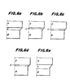
- Figs. 6(a) to (e) show embodiments in such a case.
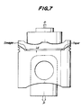
- a piston made of nodular graphite cast iron having a diameter of 120 mm shown in Fig. 7 was constituted by a piston cap made of partially stabilized zirconia (PSZ). Between the piston body and the piston cap was provided an intermediate layer made of Ti of thickness d of 2 mm and 80 mm in diameter.
- PSZ partially stabilized zirconia
- An intermediate layer made of Ti of thickness d of 2 mm and 80 mm in diameter was prepared.
- a tensile test jig was attached to each of the thus obtained pistons and a tensile test was carried out.
- the present invention is not limited to the above-mentioned embodiments, but various modifications, variations and changes are possible.
- the bonding member according to the present invention may be applied to any bonding having different coefficients of thermal expansion.
Landscapes
- Engineering & Computer Science (AREA)
- Chemical & Material Sciences (AREA)
- General Engineering & Computer Science (AREA)
- Mechanical Engineering (AREA)
- Ceramic Engineering (AREA)
- Combustion & Propulsion (AREA)
- Materials Engineering (AREA)
- Structural Engineering (AREA)
- Organic Chemistry (AREA)
- Ceramic Products (AREA)
- Pressure Welding/Diffusion-Bonding (AREA)
Abstract
Description
- The present invention relates to a method of bonding members having different coefficients of thermal expansion. Especially, the invention relates to a method suitable for bonding a ceramic member and a metallic member.
- To join members having different coefficients of thermal expansion, there is known a bonding method in which bonding is carried out with a separate intermediate layer provided at the interface between members. For instance, Japanese Utility Model Application Laid-open No. 59-160,533 discloses a method in which bonding is carried out while a cladding material made of W or Mo is interposed between a ceramic member and a metallic member as a bonding structure.
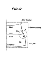
- However, since in this method a residual stress is developed at the bonding interface due to difference in thermal expansion, sufficient bonding strength cannot be obtained. This is explained by way of example for bonding of a metallic member and a ceramic member with reference to Fig. 9 of the accompanying drawings. When a metallic member having a larger coefficient of thermal expansion and a ceramic member having a smaller coefficient of thermal expansion which are bonded in a normal configuration prior to cooling are cooled for the first time, the metallic member undergoes a greater shrinkage, and as shown in Fig. 9, a tensile stress is imposed upon both the metallic member and the ceramic member at an end portion A of the interface. If this state persists, peeling or cracking is likely to take place from the interface end portion A.
- It is an object of the present invention to overcome this problem, at least partly, and to provide a method of bonding members having difference coefficients of thermal expansion so that in the product the risk of peeling or cracking at the end portion of the interface is reduced or avoided.
- The present invention is directed to a method of bonding at least two members having different coefficients of thermal expansion, characterized in that an edge of a bonding interface between the members is positioned in a tapered portion provided bridging one member having a smaller coefficient of thermal expansion and the other having a larger coefficient of thermal expansion.
- The invention also relates to the bonded composite produced by the method.
- For a better understanding of the invention, reference is made to the attached drawings which show embodiments thereof, wherein:
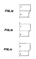
- Figs. 1(a), (b) and (c) are diagrammatical views of embodiments of tapered portions in the bonding method according to the present invention;
- Figs. 2(a) and (b) are diagrammatical views showing embodiments in which the bonding method according to the present invention is embodied in actual articles;
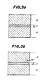
- Figs. 3(a) and (b) are diagrammatical views of members which have undergone a stress analysis;
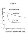
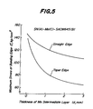
- Figs. 4 and 5 are graphs showing respective results of the stress analysis;
- Figs. 6(a) to (e) are diagrammatical views of embodiments with an intermediate layer embodying the bonding method according to the present invention;
- Fig. 7 is a diagrammatical view illustrating an embodiment in which the bonding method according to the present invention is embodied in a piston head;
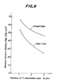
- Fig. 8 is a schematical view showing results of the stress analysis of the embodiment illustrated in Fig. 7; and
- Fig. 9 is a diagrammatical view illustrating the drawbacks possessed by the prior art bonding method discussed above.
- According to the present invention, since a tapered portion is provided at a bonding interface between the members having different coefficients of thermal expansion, bridging one member having a smaller coefficient of thermal expansion and the other member having a larger coefficient of thermal expansion, a tensile stress developed at an end portion of the interface due to difference in thermal expansion can be effectively avoided or reduced, thereby successfully preventing or reducing peeling and cracking at the interface end portion.
- Some shapes of the tapered portion are shown by way of example in Figs. 1(a), (b) and (c). As illustrated by these figures, the tapered portion may take any shape so long as a taper is provided from the joining member A (member having a smaller coefficient of thermal expansion) toward the joining member B (member having larger coefficient of thermal expansion). The shape shown in Fig. 1(a) is preferably.
- The "tapered portion" used throughout the specification and claims is defined to mean that an area of a section obtained by cutting the tapered portion in parallel with the bonding interface becomes smaller from the member A to the member B. The section of the taper may be curved instead of "straight line" as shown in Fig. 1. Further, the shape of the joining surface of the member need not be circular, but a rectangular shape or a polygonal shape may also be employed.
- The bonding method according to the present invention will be explained more in detail with reference to the following specific examples which are given in illustration thereof, but are not to be interpreted to limit the scope of the invention.
- Figs. 2(a) and (b) are diagrammatical views showing embodiments in which the bonding method according to the present invention is applied to actual articles. Fig. 2(a) is an embodiment in which the bonding method is embodied in a piston cap. The piston cap 1 made of partially stabilized zirconia is bonded to a
piston body 3 made of nodular graphite cast iron through anintermediate layer 2 made of Ti. In this embodiment, a tapered portion 4 is provided bridging piston cap 1 and theintermediate layer 2 to liberate stress. - Fig. 2(b) is an embodiment in which the bonding method according to the present invention is embodied in a rotary shaft of a turbo charger rotor, a gas turbine rotor, etc. A
shaft portion 8 of a rotary vane portion made of silicon nitride is bonded to arotary shaft 9 made of a metal through anintermediate layer 10 made of Mo having a tapering peripheral face 11. The taper 11 curves concavely, as seen in section. - The bonding method according to the present invention can be applied to any members so long as their coefficients of thermal expansion differ from each other. In particular, the bonding method according to the present invention is effective for a metallic member and a ceramic member as mentioned above. As the ceramic member used for this purpose, use may be made of silicon nitride, silicon carbide, sialon, zirconia, mullite, alumina, beryllia, etc. As the metallic member, use may be made of stainless steel, nodular graphite cast iron, nickel-chromium-molybdenium steel, chromium-molybdenuim steel, aluminum-chromium-molybdenium steel, maraging steel, precipitation-hardenable type super alloy, etc. Further, it is preferably that a part or the whole of the metallic member is hardened by precipitation hardening, nitriding, a high frequency quenching, or the like.
- Next, results obtained in the stress analysis made to confirm the effects of the tapered portion will be explained. Adopting a straight edge shown in Fig. 3(a) and a tapered edge according to the present invention shown in Fig. 3(b) as an edge of an interface, the following two cases (1) and (2) were subjected to the stress analysis while the thickness "d" of the intermediate layer was varied.
(1) member A : PSZ (partially stabilized zirconia)
member B : FCD (nodular graphite cast iron)
member C : Ti (titanium) - In the above materials, the coefficient of thermal expansion increases in the order of Ti, PSZ, and FCD (Ti<PSZ<FCD). The coefficient of thermal expansion of Ti is very near to that of PSZ. The sample is a cylindrical shape of 40 mm in diameter in which the thickness of the portion A and the portion B is 10 mm.
(2) A : SN (silicon nitride)
B : SACM (aluminum-chromium-molybdenium steel)
C : Mo (molybdenium) - In this case, the coefficient of thermal expansion becomes larger in the order of SN, Mo and SACM (SN<SO<SACM).
- Results are shown in Figs. 4 and 5. As obvious from the results in Figs. 4 and 5, it was clear in both cases that the taper edge sample according to the present invention was smaller in terms of the maximum stress as the bonding portion than the conventional straight edge sample and that stress at an edge of the bonding portion is favorably absorbed in the taper portion. Further, as compared with the samples in which the thickness of the intermediate layer is zero, that is, direct bonding is carried out through no intermediate layer, the sample provided with the intermediate layer effectively absorbed the stress at the bonding portion.
- As mentioned above, the effect of the tapered portion is larger when the intermediate layer is interposed. When the intermediate layer C is intended to be interposed in the present invention, either one of the interface between A and C or the interface between B and C has only to be positioned on the taper. Figs. 6(a) to (e) show embodiments in such a case.
- The upper portion of a piston made of nodular graphite cast iron having a diameter of 120 mm shown in Fig. 7 was constituted by a piston cap made of partially stabilized zirconia (PSZ). Between the piston body and the piston cap was provided an intermediate layer made of Ti of thickness d of 2 mm and 80 mm in diameter. A conventional piston in which an edge of an intermediate layer was straight and a piston in which a tapered portion was provided in an edge of an intermediate layer were prepared. A tensile test jig was attached to each of the thus obtained pistons and a tensile test was carried out. Consequently, the piston cap of the conventional pistons having the straight edge intermediate layer was peeled or cracked in a range of P=500 to 2,000 kgf, while neither peeling nor cracking where produced at P=2,000 kgf in the case of the piston according to the present invention with the tapered edge intermediate layer. In Fig. 8 is shown results obtained in the stress analysis with respect to the straight edge type piston and the taper edge type piston having the configuration shown in Fig. 7, with varying thickness d of the intermediate Ti layer.
- As well understood, the present invention is not limited to the above-mentioned embodiments, but various modifications, variations and changes are possible. For instance, although explanation has been made with respect to the bonding between the ceramic member and the metallic member, the bonding member according to the present invention may be applied to any bonding having different coefficients of thermal expansion.
Claims (13)
(a) a coefficient of thermal expansion between the coefficients of expansion of the said members having different coefficients of thermal expansion,
(b) having a coefficient of thermal expansion near the coefficient of thermal expansion of that one of the said two members having the smaller coefficient of thermal expansion,
(c) having a coefficient of thermal expansion near the coefficient of thermal expansion of that one of said two members having the larger coefficient of thermal expansion or
(d) being a metal having a low rigidity, is interposed between the said members whereby there are two bonding interfaces at opposite faces of the intermediate member,
characterized in that an edge of at least one of said bonding interfaces being an interface between two members having different coefficients of thermal expansion, is located at a tapered portion provided in at least one of the three members (1,2,3;8,9,10;A,B,C).
Applications Claiming Priority (2)
| Application Number | Priority Date | Filing Date | Title |
|---|---|---|---|
| JP60276941A JPS6335464A (en) | 1985-12-11 | 1985-12-11 | Method of joining different thermal expansion members |
| JP276941/85 | 1985-12-11 |
Publications (2)
| Publication Number | Publication Date |
|---|---|
| EP0232603A1 true EP0232603A1 (en) | 1987-08-19 |
| EP0232603B1 EP0232603B1 (en) | 1992-06-10 |
Family
ID=17576539
Family Applications (1)
| Application Number | Title | Priority Date | Filing Date |
|---|---|---|---|
| EP86309529A Expired - Lifetime EP0232603B1 (en) | 1985-12-11 | 1986-12-08 | A method of bonding members having different coefficients of thermal expansion |
Country Status (4)
| Country | Link |
|---|---|
| US (1) | US5163770A (en) |
| EP (1) | EP0232603B1 (en) |
| JP (1) | JPS6335464A (en) |
| DE (1) | DE3685650T2 (en) |
Cited By (4)
| Publication number | Priority date | Publication date | Assignee | Title |
|---|---|---|---|---|
| EP0311428A1 (en) * | 1987-10-07 | 1989-04-12 | Norton Company | Thermally stable joints between materials with different thermal expansion coefficients |
| EP0323207A1 (en) * | 1987-12-28 | 1989-07-05 | Ngk Insulators, Ltd. | Joined metal-ceramic assembly method of preparing the same |
| EP0287266A3 (en) * | 1987-04-06 | 1990-10-10 | Ngk Insulators, Ltd. | Joined structure comprising members of different coefficients of thermal expansion and joining method thereof |
| EP2999094A1 (en) * | 2014-09-19 | 2016-03-23 | Siemens Aktiengesellschaft | Mounting shaft for an electric motor, electric motor with a mounting shaft, use of a mounting shaft as a drive shaft of a rotary encoder and method for connecting a mounting shaft with a motor shaft of an electric motor |
Families Citing this family (10)
| Publication number | Priority date | Publication date | Assignee | Title |
|---|---|---|---|---|
| DE4021583A1 (en) * | 1990-07-06 | 1992-01-09 | Hoechst Ceram Tec Ag | CONNECTING A CERAMIC PART TO A METAL PART |
| US5769986A (en) * | 1996-08-13 | 1998-06-23 | Northrop Grumman Corporation | Stress-free bonding of dissimilar materials |
| DE19755482A1 (en) * | 1997-12-13 | 1999-06-17 | Zeiss Carl Fa | Connected body |
| US6897123B2 (en) * | 2001-03-05 | 2005-05-24 | Agityne Corporation | Bonding of parts with dissimilar thermal expansion coefficients |
| JP2003245792A (en) * | 2002-02-21 | 2003-09-02 | Sumitomo Electric Ind Ltd | Connection structure |
| US8311856B1 (en) | 2008-10-13 | 2012-11-13 | Allstate Insurance Company | Communication of insurance claim data |
| JP5438464B2 (en) * | 2009-10-29 | 2014-03-12 | 株式会社神戸製鋼所 | Dissimilar material joint |
| US9028997B2 (en) | 2012-12-28 | 2015-05-12 | General Electric Company | Ceramic collars for active brazing in sodium-based thermal batteries |
| US9105896B2 (en) | 2012-12-28 | 2015-08-11 | General Electric Company | Metal rings for active brazing in sodium-based thermal batteries |
| US9806380B2 (en) | 2013-05-31 | 2017-10-31 | General Electric Company | High temperature electrochemical cell structures, and methods for making |
Citations (2)
| Publication number | Priority date | Publication date | Assignee | Title |
|---|---|---|---|---|
| DE3506069A1 (en) * | 1984-02-28 | 1985-09-12 | NGK Insulators Ltd., Nagoya, Aichi | MACHINE PART FOR AN INTERNAL COMBUSTION ENGINE AND METHOD FOR THE PRODUCTION THEREOF |
| DE3510940A1 (en) * | 1984-03-26 | 1985-10-03 | Ngk Spark Plug Co., Ltd., Nagoya, Aichi | Turbine rotor and method for its manufacture |
Family Cites Families (19)
| Publication number | Priority date | Publication date | Assignee | Title |
|---|---|---|---|---|
| US2139431A (en) * | 1935-06-19 | 1938-12-06 | Siemens Ag | Method for applying metallic coatings to ceramic bodies |
| US2604087A (en) * | 1948-09-22 | 1952-07-22 | Simmonds Aerocessories Inc | Spark plug |
| US2657961A (en) * | 1950-03-15 | 1953-11-03 | Maschf Augsburg Nuernberg Ag | Piston for internal-combustion engines |
| US3063144A (en) * | 1956-04-16 | 1962-11-13 | American Lava Corp | Metal-to-ceramic seals |
| US3065533A (en) * | 1960-08-11 | 1962-11-27 | Honeywell Regulator Co | Method of making ceramic-metal seals |
| US3302961A (en) * | 1961-04-14 | 1967-02-07 | Philips Corp | Compression ceramic-metal seal |
| US3314140A (en) * | 1964-05-14 | 1967-04-18 | Merritt W Albright | Method of making a surface joint |
| US3549337A (en) * | 1968-03-05 | 1970-12-22 | Du Pont | Method of securing dense,metal-bonded refractory nitride bodies to steel |
| FR2159632A5 (en) * | 1971-11-05 | 1973-06-22 | Thomson Csf | |
| JPS5924242B2 (en) * | 1976-03-31 | 1984-06-08 | 株式会社東芝 | Turbine rotor structure |
| DE2828749C2 (en) * | 1978-06-30 | 1983-10-20 | M.A.N. Maschinenfabrik Augsburg-Nürnberg AG, 8500 Nürnberg | Pistons for internal combustion engines |
| JPS55121978A (en) * | 1979-03-16 | 1980-09-19 | Tokyo Shibaura Electric Co | Bonding structure of ceramic and metal |
| JPS55122667A (en) * | 1979-03-16 | 1980-09-20 | Toshiba Corp | Sealing structure body of ceramic and metal |
| DE3240224A1 (en) * | 1982-09-08 | 1984-03-08 | Alcan Aluminiumwerk Nürnberg GmbH, 6000 Frankfurt | Piston for internal combustion engines |
| JPS6082267A (en) * | 1983-10-06 | 1985-05-10 | Nissan Motor Co Ltd | Joint structure between ceramic shaft and metallic shaft |
| JPS60190651A (en) * | 1984-03-12 | 1985-09-28 | Ngk Insulators Ltd | Engine piston and manufacturing method thereof |
| GB2158185B (en) * | 1984-05-01 | 1987-08-05 | Ae Plc | Reinforced light metal pistons |
| JPS61215270A (en) * | 1985-03-15 | 1986-09-25 | 日本特殊陶業株式会社 | Turbine rotor |
| JPS63139077A (en) * | 1986-12-02 | 1988-06-10 | 工業技術院長 | Method of joining different kind materials of different thermal expansion coefficient |
-
1985
- 1985-12-11 JP JP60276941A patent/JPS6335464A/en active Granted
-
1986
- 1986-12-08 DE DE8686309529T patent/DE3685650T2/en not_active Expired - Lifetime
- 1986-12-08 EP EP86309529A patent/EP0232603B1/en not_active Expired - Lifetime
-
1990
- 1990-04-05 US US07/504,697 patent/US5163770A/en not_active Expired - Lifetime
Patent Citations (2)
| Publication number | Priority date | Publication date | Assignee | Title |
|---|---|---|---|---|
| DE3506069A1 (en) * | 1984-02-28 | 1985-09-12 | NGK Insulators Ltd., Nagoya, Aichi | MACHINE PART FOR AN INTERNAL COMBUSTION ENGINE AND METHOD FOR THE PRODUCTION THEREOF |
| DE3510940A1 (en) * | 1984-03-26 | 1985-10-03 | Ngk Spark Plug Co., Ltd., Nagoya, Aichi | Turbine rotor and method for its manufacture |
Non-Patent Citations (3)
| Title |
|---|
| CHEMICAL ABSTRACTS, vol. 103, no. 18, 4th November 1985, page 271, abstract no. 146220p, Columbus, Ohio, US; & JP-A-60 82 267 (NISSAN MOTOR CO., LTD) * |
| CHEMICAL ABSTRACTS, vol. 94, no. 18, 4th May 1981, page 300, abstract no. 144304r, Columbus, Ohio, US; & JP-A-80 121 978 (TOKYO SHIBAURA ELECTRIC Co. LTD) 19-09-1980 * |
| CHEMICAL ABSTRACTS, vol. 94, no. 18, 4th May 1981, page 300, abstract no. 144306t, Columbus, Ohio, US; & JP-A-80 122 667 (TOKYO SHIBAURA ELECTRIC CO., LTD) 20-09-1980 * |
Cited By (11)
| Publication number | Priority date | Publication date | Assignee | Title |
|---|---|---|---|---|
| EP0287266A3 (en) * | 1987-04-06 | 1990-10-10 | Ngk Insulators, Ltd. | Joined structure comprising members of different coefficients of thermal expansion and joining method thereof |
| US5161908A (en) * | 1987-04-06 | 1992-11-10 | Ngk Insulators, Ltd. | Joined structure comprising members of different coefficients of thermal expansion and joining method thereof |
| EP0311428A1 (en) * | 1987-10-07 | 1989-04-12 | Norton Company | Thermally stable joints between materials with different thermal expansion coefficients |
| EP0323207A1 (en) * | 1987-12-28 | 1989-07-05 | Ngk Insulators, Ltd. | Joined metal-ceramic assembly method of preparing the same |
| US4959258A (en) * | 1987-12-28 | 1990-09-25 | Ngk Insulators, Ltd. | Joined metal-ceramic assembly method of preparing the same |
| EP2999094A1 (en) * | 2014-09-19 | 2016-03-23 | Siemens Aktiengesellschaft | Mounting shaft for an electric motor, electric motor with a mounting shaft, use of a mounting shaft as a drive shaft of a rotary encoder and method for connecting a mounting shaft with a motor shaft of an electric motor |
| CN105443562A (en) * | 2014-09-19 | 2016-03-30 | 西门子公司 | Electric motor, add-on shaft, and method for connecting add-on shaft with motor shaft of electric motor |
| CN105443562B (en) * | 2014-09-19 | 2018-07-10 | 西门子公司 | Motor, additional shaft and its application and the method for connection additional shaft and motor reel |
| US10294981B2 (en) | 2014-09-19 | 2019-05-21 | Siemens Aktiengesellschaft | Add-on drive shaft for an encoder or impeller fan and method for adding the shaft |
| EP2999094B1 (en) | 2014-09-19 | 2021-10-27 | Siemens Aktiengesellschaft | Mounting shaft for an electric motor, electric motor with a mounting shaft, use of a mounting shaft as a drive shaft of a rotary encoder and method for connecting a mounting shaft with a motor shaft of an electric motor |
| EP3965270A1 (en) * | 2014-09-19 | 2022-03-09 | Siemens Aktiengesellschaft | Mounting shaft for an electric motor, electric motor with a mounting shaft, use of a mounting shaft as a drive shaft of a rotary encoder and method for connecting a mounting shaft with a motor shaft of an electric motor |
Also Published As
| Publication number | Publication date |
|---|---|
| DE3685650T2 (en) | 1992-12-24 |
| US5163770A (en) | 1992-11-17 |
| EP0232603B1 (en) | 1992-06-10 |
| JPH0444631B2 (en) | 1992-07-22 |
| DE3685650D1 (en) | 1992-07-16 |
| JPS6335464A (en) | 1988-02-16 |
Similar Documents
| Publication | Publication Date | Title |
|---|---|---|
| EP0142334B1 (en) | A metal-ceramic composite body and a method of manufacturing the same | |
| EP0232603B1 (en) | A method of bonding members having different coefficients of thermal expansion | |
| US5161908A (en) | Joined structure comprising members of different coefficients of thermal expansion and joining method thereof | |
| EP0224345B1 (en) | Valve seat insert and cylinder head with the valve seat insert | |
| JPS62104696A (en) | Metallic ceramics junction body and metallic ceramics coupling body formed by using said body | |
| US5028162A (en) | Metal-ceramic joined composite bodies | |
| US4856970A (en) | Metal-ceramic combination | |
| US4874674A (en) | Metal-ceramic composite bodies | |
| EP0323207B1 (en) | Joined metal-ceramic assembly method of preparing the same | |
| US4865896A (en) | Composite joined bodies including an intermediate member having a honeycomb structure | |
| JPH02171237A (en) | Ceramic and metallic couple | |
| JPH063171B2 (en) | Ceramic-Metal Friction Welding Body and Ceramic Casting Piston Composed of It | |
| JP2542044B2 (en) | Metal / ceramic joints | |
| JP2538989B2 (en) | Metal / ceramic joints | |
| JPS6325281Y2 (en) | ||
| JPH0648853A (en) | Joint structure of ceramic member and metal member | |
| JP2572803B2 (en) | Metal / ceramic joints | |
| JPH05321757A (en) | Engine parts and its manufacture |
Legal Events
| Date | Code | Title | Description |
|---|---|---|---|
| PUAI | Public reference made under article 153(3) epc to a published international application that has entered the european phase |
Free format text: ORIGINAL CODE: 0009012 |
|
| AK | Designated contracting states |
Kind code of ref document: A1 Designated state(s): DE GB SE |
|
| 17P | Request for examination filed |
Effective date: 19880205 |
|
| 17Q | First examination report despatched |
Effective date: 19890608 |
|
| GRAA | (expected) grant |
Free format text: ORIGINAL CODE: 0009210 |
|
| AK | Designated contracting states |
Kind code of ref document: B1 Designated state(s): DE GB SE |
|
| REF | Corresponds to: |
Ref document number: 3685650 Country of ref document: DE Date of ref document: 19920716 |
|
| PLBE | No opposition filed within time limit |
Free format text: ORIGINAL CODE: 0009261 |
|
| STAA | Information on the status of an ep patent application or granted ep patent |
Free format text: STATUS: NO OPPOSITION FILED WITHIN TIME LIMIT |
|
| 26N | No opposition filed | ||
| EAL | Se: european patent in force in sweden |
Ref document number: 86309529.5 |
|
| PGFP | Annual fee paid to national office [announced via postgrant information from national office to epo] |
Ref country code: GB Payment date: 19971128 Year of fee payment: 12 |
|
| PGFP | Annual fee paid to national office [announced via postgrant information from national office to epo] |
Ref country code: SE Payment date: 19971215 Year of fee payment: 12 |
|
| PGFP | Annual fee paid to national office [announced via postgrant information from national office to epo] |
Ref country code: DE Payment date: 19971229 Year of fee payment: 12 |
|
| PG25 | Lapsed in a contracting state [announced via postgrant information from national office to epo] |
Ref country code: GB Free format text: LAPSE BECAUSE OF NON-PAYMENT OF DUE FEES Effective date: 19981208 |
|
| PG25 | Lapsed in a contracting state [announced via postgrant information from national office to epo] |
Ref country code: SE Free format text: LAPSE BECAUSE OF NON-PAYMENT OF DUE FEES Effective date: 19981209 |
|
| GBPC | Gb: european patent ceased through non-payment of renewal fee |
Effective date: 19981208 |
|
| PG25 | Lapsed in a contracting state [announced via postgrant information from national office to epo] |
Ref country code: DE Free format text: LAPSE BECAUSE OF NON-PAYMENT OF DUE FEES Effective date: 19991001 |