EP0231950A2 - Verfahren zur nichtlinearen A/D-Wandlung - Google Patents
Verfahren zur nichtlinearen A/D-Wandlung Download PDFInfo
- Publication number
- EP0231950A2 EP0231950A2 EP87101659A EP87101659A EP0231950A2 EP 0231950 A2 EP0231950 A2 EP 0231950A2 EP 87101659 A EP87101659 A EP 87101659A EP 87101659 A EP87101659 A EP 87101659A EP 0231950 A2 EP0231950 A2 EP 0231950A2
- Authority
- EP
- European Patent Office
- Prior art keywords
- conversion
- characteristic
- data
- analog
- linear
- Prior art date
- Legal status (The legal status is an assumption and is not a legal conclusion. Google has not performed a legal analysis and makes no representation as to the accuracy of the status listed.)
- Withdrawn
Links
- 238000006243 chemical reaction Methods 0.000 title claims abstract description 83
- 238000000034 method Methods 0.000 title claims description 21
- 238000012886 linear function Methods 0.000 claims 2
- 230000000007 visual effect Effects 0.000 description 8
- 230000006870 function Effects 0.000 description 6
- 230000015572 biosynthetic process Effects 0.000 description 4
- 238000003786 synthesis reaction Methods 0.000 description 4
- 238000010586 diagram Methods 0.000 description 3
- 230000006866 deterioration Effects 0.000 description 2
- 238000005259 measurement Methods 0.000 description 2
- 238000013139 quantization Methods 0.000 description 2
- 230000004304 visual acuity Effects 0.000 description 2
- 230000000694 effects Effects 0.000 description 1
Images


Classifications
-
- H—ELECTRICITY
- H03—ELECTRONIC CIRCUITRY
- H03M—CODING; DECODING; CODE CONVERSION IN GENERAL
- H03M1/00—Analogue/digital conversion; Digital/analogue conversion
- H03M1/12—Analogue/digital converters
- H03M1/48—Servo-type converters
Definitions
- the present invention relates to a method of converting an electric analog signal into digital signals by using a non-linear A/D converter.
- the A/D conversion needs to be performed with sufficiently fine digitization intervals. Since the density interval which can be perceived by human eyes differ between the light and the dark side, the deterioration of the quality of the reproduced image due to the discontinuity of the density can be minimized if the A/D conversion is performed with a minimum necessary number of bits depending on this difference.
- the A/D conversion can be performed with N bit digitization over a density range from the maximum density D max to the minimum density D min on the basis of the relation between the above-mentioned function and the density so that the change ⁇ L* in the human visual characteristic with regard to the digitization interval is constant [(L* max - L * m i n )/(2 N - 1)].
- This variable quantization is ideal and the deterioration of the quality of the reproduced image can be avoided.
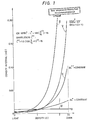
- Pig. 1 shows curves each indicating the relation between the density D of a reproduced image and the density interval ⁇ D with eight bit digitization.
- the density D is shown along the abscissa and the density interval ⁇ D is shown along the ordinate in Fig. 1.
- Curves I and II indicate ideal oases of ⁇ L* and ⁇ L** respectively being held constant. For the ideal oases, the density range of between 0 and 2.4 is illustrated.
- Curve III indicates the relation between the density and the density interval in the linear A/D conversion. It is understood from the ideal curves I and II and the linear curve III that the density can be finely divided at its lower portion (light side) but is roughly divided at its higher portion (dark side). Therefore, the density interval becomes larger at the higher end of the density due to the human visual characteristic.
- Curve IV indicates the relation between the density and the density interval in the logarithmic conversion over the same density range. It is understood from the logarithmic curve I V that it is nearer to the ideal curves I and II. However, this density is divided at its higher end more finely than the actual resolving power of the human eye so as to make the density appear to be smoothly changing, but the discontinuity of the density looks conspicuous at its lower end.
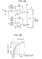
- Fig. 2A shows the basic circuit constitution of the conventional nonlinear A/D converter 10.
- a converting section (ADC) 12 converts an input analog signal into output digital signals.
- the output terminal of a first amplifier 14 is connected to the signal input terminal V IN of the converting section 12.
- the negative terminal of the first amplifier 14 is connected to an image signal input terminal 16 through a resistor R 1 , and the positive terminal of the first amplifier is grounded.
- a feedback resistor R 2 is connected between the negative terminal and output terminal of the first amplifier 14.
- the negative terminal of the first amplifier 14 is connected to a power supply through an offset adjustment resistor R O .
- the output terminal of a second amplifier 18 is connected to the reference input terminal V REF of the converting section 12.
- the negative terminal of the second amplifier 18 is connected to the image signal input terminal 16 through a gain adjustment resistor R G and is also connected to the power supply through a bias adjustment resistor R B .
- a feedback resistor R 3 connects the output terminal and the negative input terminal of the second amplifier 18.
- the positive terminal of the second amplifier 18 is grounded.
- the conversion output signal E of the nonlinear A/D converter 10 can be expressed as where x denotes an input image signal, ax + b denotes a reference signal, N denotes the number of bits in digitization, a coefficient a is determined by the gain, and another coefficient b is determined by the bias.
- Fig. 2B The analog inputs to the converter 12 and the digital outputs therefrom are shown along the abscissa and the ordinate, respectively, in Fig. 2B. It is understood from Fig. 2B that the resolving power for the digital output from the nonlinear A/D converter can be altered depending on the level of the analog input.
- the nonlinear A/D converter 10 having the above-described conversion characteristic is provided in an image signal processor, the visual discontinuity of a reproduced image, which has been a problem in the conventional art, can be reduced to make the density or gradation of the image look to be naturally changing to human eyes.
- the nonlinear conversion characteristic is affected by the irregularities of the components of the image signal processor so that the conversion characteristic varies from processor to processor. For that reason, there is a problem that reproduced images of the same density cannot be obtained when the identical original image is read by different processors.
- an electric input analog signal whose level changes is converted into digital signals by a nonlinear A/D converter.
- conversion characteristic data on the nonlinear A/D converter are measured first.
- Digital values compensated on the basis of previously obtained reference data and corresponding to the level of the electric input analog signal are obtained in terms of the measured conversion characteristic data and then stored in a look-up table memory. The stored digital values are used as the digital signals corresponding to the analog signal actually inputted.
- the measured conversion characteristic data are used as data in conversion from a linear characteristic to a nonlinear characteristic.
- the previously obtained reference data are used as values in conversion from the linear characteristic to a logarithmic characteristic.
- the digital values are used as values in conversion from the nonlinear characteristic to the logarithmic characteristic.
- the electric input analog signal is an image signal obtained by reading the original image on paper, a film or the like.
- the conversion characteristic of the nonlinear A/D converter is measured for each image signal processor in which the converter is provided.
- the irregularities of the components of the processor and its characteristics are thus compensated so that the digital output signals having the proper digital values are generated correspondingly to the electric input analog signal.
- Fig. 3 shows a block diagram of an example of the main part of an image signal processor to which the nonlinear A/D conversion method is applied.
- the main part is a circuit in which an analog image signal obtained by reading the original image on paper, a film or the like is subjected to nonlinear A/D conversion to generate a digital signal which is sent out from the circuit to a line memory (not shown in the drawings) for image signal processing or to another processing circuit.
- Fig. 3 shows an input section 20 for reading the original image to generate the analog image signal which is an electric input analog signal.
- the input section 20 includes a photomultiplier (PMT) 21 and an operational amplifier 22 (OP AMP).
- a nonlinear A/D converter (NL A/ D CONV.) 30 performs the A/D conversion of the input image signal x to generate a provisional digital signal s.
- Compensated digital values z' corresponding to the provisional digital signals z are stored in a look-up table memory (LUT) 40.
- the compensated digital value z' corresponding to the provisional digital signal is read as a converted digital signal out of the look-up table memory 40 and sent out to a next section.
- the electric components include a switch 23, a first synthesis circuit 24, a first operational amplifier 25, a first multiplying D/A converter 26, a second synthesis circuit 27 and a second operational amplifier 28 which are connected in series with each other between the input section 20 and the nonlinear A/D converter 30.
- a controller 29 regulates the whole circuit shown in Fig. 3.
- the oontroller 29 includes a CPU and other necessary control circuits which are not specifically shown in Fig. 3.
- the first synthesis circuit 24 functions so that an offset signal for adjusting the offset of the input image signal, which is produced by the combination of the input section 20, the first operational amplifier 25 and the first multiplying D/A converter 26, is applied (added) to the image signal.
- a signal from a first register 31 is supplied as the offset signal through a second multiplying D/ A converter 32 in accordance with a command from the controller 29.
- the first multiplying D/A converter 26 functions so as to adjust the gain of the input image signal.
- a gain value stored in a RAM 33 is read out of it and supplied to the first multiplying D/A converter 26 through a second register 34, in accordance with a command from the controller 29.
- the second synthesis circuit 27 functions so that an Offset produced by the operational amplifier 28 and the nonlinear A/D converter 30 is adjusted.
- a signal from a third register 35 is supplied as an offset signal through a third multiplying D/A converter 36 in accordance with a command from the controller 29, in the same manner as the above-mentioned adjustment of the preceding offset.
- the switch 23 functions so that the input image signal from the input section 20 and an input signal having a prescribed constant value and supplied from a terminal 37 at the time of the measurement of a characteristic are changed over from one to the other in accordance with a command from the controller 29.
- the output z of the nonlinear A/D converter 30 or the output z' of the look-up table memory 40 can be entered into the CPU of the controller 29. Data can be stored in the look-up table memory 40 from the CPU.
- the multiplying D/A converters 26, 32 and 36 are also denoted by DAC-08 in Fig. 3.
- Fig. 4 shows a flow chart of operational steps of the method
- Fig. 5 shows a characteristic curve for explaining a conversion characteristic used for describing the present invention.
- the circuit shown in Fig. 3 is put in operation in step S1.
- the switch 23 is shifted to a terminal for a prescribed input signal I of IV in accordance with a command from the controller 29.
- Conversion data falling on a straight line with an inclination of 45° are written from the CPU of the controller 29 into the look-up table memory 40 in a step S2. This means that the output of the nonlinear A/D converter 30 is outputted from the look-up table memory 40 while effecting no change thereto.
- step S3 values, all of which are set to zero, are written into the RAM 33 in accordance with a command from the controller 29. These zero values are supplied to the D/A converter 26 through the second register 34 to zero the output x of the converter 26.
- the step S4 the offsets of the operational amplifier 28 and the nonlinear A/D converter 30 are adjusted by the use of the third register 35 in accordance with a command from the controller 29.
- a and b are supposed to be optionally adjusted values except for zero.
- a conversion characteristic data curve is plotted in Fig. 5 showing the output of the RAM along the axis of abscissa and that of the nonlinear A/D converter 30 or that of the look-up table memory 40 along the axis of ordinate.
- the start point of the conversion characteristic data curve can be set at the origin (0, 0).
- step S5 N-bit data (which are 8-bit data in this case), namely 0, 1, 2, 3, ... and 255 are written into the RAM 33. If the switch 23 is not already shifted to the reference terminal 3 7 , the switch is shifted thereto.
- the maximum data value (Z N - 1) (which is 255 in this case) in the RAM 33 is read out of the second register 34.
- the offset value of the first register 31 is determined and then fixed so that the output of the look-up table memory 40 becomes a correponding value (2 N - 1), which is 255 in this case.
- the FF H i.e. 255, value of the output of the RAM 33 and that of the output of the look-up table memory 40 are thus made to coincide with each other at the upper end point of the conversion characteristic data curve shown in Fig. 5.
- step S7 the data 0, 1, 2, 3, ..., (2 N - 1), ... and 255 written in the RAM 33 are sequentially read out of the second register 34 in accordance with a command from the controller 29 which has the effect of reading the corresponding output produced on the look-up table memory 40.
- the conversion characteristic of the nonlinear A/D converter 30 is obtained as shown in Fig. 5A.
- the characteristic data include the irregularities of the components of the image signal processor and its inherent characteristics.
- the digital values from zero (0) to FF on the axis of abscissa in Fig. 5 A correspond linearly to levels of electric input analog signal which is indicative of the amount of light received after having passed through the film or having been reflected on the paper or the like. While the levels of the input signal and the corresponding digital valuee represent a linear characteristic, the corresponding outputs of the look-up table memory 40 are nonlinear due to the conversion characteristic of the nonlinear A/D converter 30. On the other hand, density values (or values proportional thereto) having a logarithmic characteristics with respect to the input signal have previously been written in the memory (not shown) of the CPU of the controller 29. The density values can be obtained by subjecting the input signal to logarithmic conversion.
- Fig. SA The relation of the digital values corresponding to the input signal and the density values is indicated by the curve in the region I of Fig. 5B.
- the curve of Fig. SA is depicted symmetrically with respect to the axis of abscissa in the region IV of Fig. 5B.
- step S8 compensated digital values corresponding to the level of the input signal are calculated in terms of the reference data and the conversion characteristic data in the memory of the controller 29, and then stored in the look-up tabale memory 40. More specifically, referring to the curve shown in region IV of Fig. 5B, the digital values on the axis of lower aide ordinate corresponding respectively to the consecutive digital values on the axis of right side abscissa are nonconsecutive numbers. With this nonconsecutive digital values, new consecutive digital values from zero (0) to FF which are referred to as compensated digital values are made to be in one-to-one correspondence. The curve in the region II of Fig. 5B is drawn to indicate the density level for the respective compensated digital values.
- the data on this curve are stored in the look-up table memory 40.
- the operation is thus completed in a step S9. Since the measured conversion characteristic data are data in the conversion from the linear characteristic to the nonlinear characteristic and the reference data are the value in the conversion from the linear characteristic to the logarithmic characteristic, values in digital conversion from the nonlinear characteristic to the logarithmic characteristic can be easily calculated in terms of the conversion characteristic data and the reference data.
- the CPU of the controller 29 includes a read/write circuit (not shown in the drawings) for reading in the output of the look-up table memory 40 and writing the read output into the look-up table memory 40 in order to perform the offset adjustment for the start and end points of the above-mentioned conversion characteristic data curve.
- the read/write circuit can be easily manufactured by conventional electronic circuit techniques.
- the CPU of the controller 29 also includes a means (not shown in the drawings) for calculating values in conversion from the nonlinear characteristic to the linear characteristic, and a means (not shown in the drawings) for calculating the values in the conversion from the linear characteristic to the logarithmic characteristic, in order to perform conversion from the nonlinear characteristic to the logarithmic characteristic.
- the digital values stored in the look-up table memory 40 are compensated digital values which are density values exactly corresponding to the change in the density of the image.
- the relation between the density and the density interval has a characteristic shown by the curve V in Fig. 1 and is similar to the ideal characteristic shown by the curve II which indicates the case of ⁇ L** being held constant.
- the coefficients a and b are set at 0.65 and -0.7 respectively and a condition of 0 ⁇ x ⁇ -2 is set for the curve V, the values for a, b and x are not confined to these conditions It is understood from the curve V that the visual characteristic is improved especially at the lower portion of the density, and the discontinuity of gradation at the lower portion of the density is thus reduced so as to make the reproduced image look with substantially continuous gradation to human eyes.
- the switch 23 is first shifted to the input section 20 to read an ordinary white reference plate and an ordinary black reference plate to calibrate the image signal processor, as in the prior art. After that, the reading of the original image is started.
- digital density values corresponding to the analog values of the read image signal are sequentially read out of the look-up table memory 40 and sent out as digital signals to the next section.
- the present invention is not confined to the above-described embodiment, but can be applied to aural signal processing as wall.
- a nonlinear conversion characteristic can be made similar to an ideal visual conversion characteristic or the like, as described above, so that a reproduced image or the like is perceived as having a continuously changing distribution of density. Even if the nonlinear A/D conversion characteristic has an irregularity, the irregularity is automatically compensated to enable image processing with good reproduced gradation without being affected by the characteristic of the image signal processor or the like.
Landscapes
- Engineering & Computer Science (AREA)
- Theoretical Computer Science (AREA)
- Facsimile Image Signal Circuits (AREA)
- Analogue/Digital Conversion (AREA)
Applications Claiming Priority (2)
| Application Number | Priority Date | Filing Date | Title |
|---|---|---|---|
| JP25552/86 | 1986-02-07 | ||
| JP61025552A JPS62183677A (ja) | 1986-02-07 | 1986-02-07 | 非線形a/d変換方法 |
Publications (2)
| Publication Number | Publication Date |
|---|---|
| EP0231950A2 true EP0231950A2 (de) | 1987-08-12 |
| EP0231950A3 EP0231950A3 (de) | 1990-10-03 |
Family
ID=12169120
Family Applications (1)
| Application Number | Title | Priority Date | Filing Date |
|---|---|---|---|
| EP19870101659 Withdrawn EP0231950A3 (de) | 1986-02-07 | 1987-02-06 | Verfahren zur nichtlinearen A/D-Wandlung |
Country Status (3)
| Country | Link |
|---|---|
| US (1) | US4764751A (de) |
| EP (1) | EP0231950A3 (de) |
| JP (1) | JPS62183677A (de) |
Cited By (9)
| Publication number | Priority date | Publication date | Assignee | Title |
|---|---|---|---|---|
| EP0464777A1 (de) * | 1990-07-03 | 1992-01-08 | Zumtobel Aktiengesellschaft | Schaltungsanordnung zum Annähern einer nichtlinearen Übertragungsfunktion |
| WO1992002071A3 (en) * | 1990-07-16 | 1992-03-19 | Eastman Kodak Co | Adaptive dual range analog to digital converter |
| EP0514587A3 (en) * | 1991-05-24 | 1993-09-22 | Samsung Electronics Co., Ltd. | A process of linearizing non-linear analog-to-digital conversion the process and circuit for performing |
| WO1996009692A1 (en) * | 1994-09-23 | 1996-03-28 | National Semiconductor Corporation | An efficient architecture for correcting component mismatches and circuit nonlinearities in a/d converters |
| US5782762A (en) * | 1994-10-27 | 1998-07-21 | Wake Forest University | Method and system for producing interactive, three-dimensional renderings of selected body organs having hollow lumens to enable simulated movement through the lumen |
| US6366800B1 (en) | 1994-10-27 | 2002-04-02 | Wake Forest University | Automatic analysis in virtual endoscopy |
| US6694163B1 (en) | 1994-10-27 | 2004-02-17 | Wake Forest University Health Sciences | Method and system for producing interactive, three-dimensional renderings of selected body organs having hollow lumens to enable simulated movement through the lumen |
| US7747055B1 (en) | 1998-11-25 | 2010-06-29 | Wake Forest University Health Sciences | Virtual endoscopy with improved image segmentation and lesion detection |
| US8682045B2 (en) | 1997-02-25 | 2014-03-25 | Wake Forest University Health Sciences | Virtual endoscopy with improved image segmentation and lesion detection |
Families Citing this family (5)
| Publication number | Priority date | Publication date | Assignee | Title |
|---|---|---|---|---|
| GB2189970B (en) * | 1986-05-01 | 1990-03-28 | British Broadcasting Corp | Data conversion |
| NL8802732A (nl) * | 1988-11-08 | 1990-06-01 | Philips Nv | Magnetische resonantiewerkwijze en -inrichting. |
| IT1232088B (it) * | 1989-05-04 | 1992-01-23 | Bruttini Roberto | Strumento di misura e controllo digitale programmabile particolarmente per segnali non lineari |
| US6536268B1 (en) * | 1999-11-01 | 2003-03-25 | Siemens Vdo Automotive Corporation | Utilizing increasing width for identification voltages |
| EP2747290A1 (de) * | 2012-12-18 | 2014-06-25 | ams AG | Analog-Digital-Umsetzersystem, Sensoranordnung und Verfahren zur Analog-Digital-Umsetzung |
Family Cites Families (4)
| Publication number | Priority date | Publication date | Assignee | Title |
|---|---|---|---|---|
| US4031530A (en) * | 1975-10-22 | 1977-06-21 | Instrulab Incorporated | Digital second-order clock linearizer |
| FR2427013A1 (fr) * | 1978-05-24 | 1979-12-21 | Efcis | Procede d'autocorrection de resultats errones delivres par une chaine d'acquisition de donnees et systeme autocorrecteur pour la mise en oeuvre de ce procede |
| JPS56157577A (en) * | 1980-05-09 | 1981-12-04 | Hitachi Ltd | Signal procession device |
| JPS5753145A (en) * | 1980-09-16 | 1982-03-30 | Sony Tektronix Corp | Calibrator for analogue-digital converter |
-
1986
- 1986-02-07 JP JP61025552A patent/JPS62183677A/ja active Pending
-
1987
- 1987-02-06 EP EP19870101659 patent/EP0231950A3/de not_active Withdrawn
- 1987-02-09 US US07/012,406 patent/US4764751A/en not_active Expired - Lifetime
Cited By (16)
| Publication number | Priority date | Publication date | Assignee | Title |
|---|---|---|---|---|
| EP0464777A1 (de) * | 1990-07-03 | 1992-01-08 | Zumtobel Aktiengesellschaft | Schaltungsanordnung zum Annähern einer nichtlinearen Übertragungsfunktion |
| WO1992002071A3 (en) * | 1990-07-16 | 1992-03-19 | Eastman Kodak Co | Adaptive dual range analog to digital converter |
| EP0514587A3 (en) * | 1991-05-24 | 1993-09-22 | Samsung Electronics Co., Ltd. | A process of linearizing non-linear analog-to-digital conversion the process and circuit for performing |
| WO1996009692A1 (en) * | 1994-09-23 | 1996-03-28 | National Semiconductor Corporation | An efficient architecture for correcting component mismatches and circuit nonlinearities in a/d converters |
| US6909913B2 (en) | 1994-10-27 | 2005-06-21 | Wake Forest University Health Sciences | Method and system for producing interactive three-dimensional renderings of selected body organs having hollow lumens to enable simulated movement through the lumen |
| US6272366B1 (en) | 1994-10-27 | 2001-08-07 | Wake Forest University | Method and system for producing interactive three-dimensional renderings of selected body organs having hollow lumens to enable simulated movement through the lumen |
| US6366800B1 (en) | 1994-10-27 | 2002-04-02 | Wake Forest University | Automatic analysis in virtual endoscopy |
| US6694163B1 (en) | 1994-10-27 | 2004-02-17 | Wake Forest University Health Sciences | Method and system for producing interactive, three-dimensional renderings of selected body organs having hollow lumens to enable simulated movement through the lumen |
| US5782762A (en) * | 1994-10-27 | 1998-07-21 | Wake Forest University | Method and system for producing interactive, three-dimensional renderings of selected body organs having hollow lumens to enable simulated movement through the lumen |
| US7149564B2 (en) | 1994-10-27 | 2006-12-12 | Wake Forest University Health Sciences | Automatic analysis in virtual endoscopy |
| US7792565B2 (en) | 1994-10-27 | 2010-09-07 | Wake Forest University Health Sciences | Method and system for producing interactive, three-dimensional renderings of selected body organs having hollow lumens to enable simulated movement through the lumen |
| US7853310B2 (en) | 1994-10-27 | 2010-12-14 | Wake Forest University Health Sciences | Automatic analysis in virtual endoscopy |
| US8145292B2 (en) | 1994-10-27 | 2012-03-27 | Wake Forest University Health Sciences | Method and system for producing interactive, three-dimensional renderings of selected body organs having hollow lumens to enable simulated movement through the lumen |
| US8275446B2 (en) | 1994-10-27 | 2012-09-25 | Wake Forest University Health Sciences | Automatic analysis in virtual endoscopy |
| US8682045B2 (en) | 1997-02-25 | 2014-03-25 | Wake Forest University Health Sciences | Virtual endoscopy with improved image segmentation and lesion detection |
| US7747055B1 (en) | 1998-11-25 | 2010-06-29 | Wake Forest University Health Sciences | Virtual endoscopy with improved image segmentation and lesion detection |
Also Published As
| Publication number | Publication date |
|---|---|
| US4764751A (en) | 1988-08-16 |
| EP0231950A3 (de) | 1990-10-03 |
| JPS62183677A (ja) | 1987-08-12 |
Similar Documents
| Publication | Publication Date | Title |
|---|---|---|
| US4764751A (en) | Method of nonlinear A/D conversion | |
| EP0482790B1 (de) | Verfahren und Gerät zur Erzeugung einer Darstellung eines Bildes | |
| US5815291A (en) | Image reading apparatus | |
| US4578715A (en) | Picture signal quantizing circuit | |
| EP0310021B1 (de) | Gradationsumsetzungsschaltung unter Benutzung einer Nachschlagetabelle | |
| US4847695A (en) | Image processing apparatus in which the minimum and maximum widths of a pulse-width modulated signal can be independently adjusted in accordance with predetermined data signals | |
| US4736245A (en) | Calibration method for color film inspection system | |
| US6903714B2 (en) | Gray level conversion method and display device | |
| US4893180A (en) | Color image signal processing method | |
| US4539600A (en) | Image signal processing with a variable threshold | |
| EP0178044A2 (de) | Analog/Digital Wandlungsgerät für Videosignale | |
| US5134503A (en) | Image processing apparatus | |
| GB1581817A (en) | Signal processing apparatus | |
| US4723174A (en) | Picture image processor | |
| EP0484924A2 (de) | Bildsignalkorrekturschaltungsanordnung zur Verwendung in einem Bilddatenverarbeitungsgerät | |
| US5191445A (en) | Image reader | |
| US4829584A (en) | Image input system | |
| US5506698A (en) | Image reproducing apparatus and process wherein minimized average error technique is used for each of fractions of original pel intensity value | |
| HK1006485A1 (en) | Compensation for drift in a cathode ray tube | |
| US6067175A (en) | Method for white balance | |
| JP2650969B2 (ja) | デジタルテレビジョンカメラ装置 | |
| JPS5820092A (ja) | カラ−テレビジヨンカメラの自動調整方式 | |
| EP0673149A1 (de) | Verfahren und Vorrichtung zur Korrektur der Nichtgleichheit des Dunkelsignals eines Bildsensors | |
| JPH0563977A (ja) | イメージセンサ | |
| JP3254749B2 (ja) | 画像読み取り装置 |
Legal Events
| Date | Code | Title | Description |
|---|---|---|---|
| PUAI | Public reference made under article 153(3) epc to a published international application that has entered the european phase |
Free format text: ORIGINAL CODE: 0009012 |
|
| AK | Designated contracting states |
Kind code of ref document: A2 Designated state(s): DE FR GB |
|
| PUAL | Search report despatched |
Free format text: ORIGINAL CODE: 0009013 |
|
| AK | Designated contracting states |
Kind code of ref document: A3 Designated state(s): DE FR GB |
|
| 17P | Request for examination filed |
Effective date: 19910314 |
|
| 17Q | First examination report despatched |
Effective date: 19920415 |
|
| STAA | Information on the status of an ep patent application or granted ep patent |
Free format text: STATUS: THE APPLICATION IS DEEMED TO BE WITHDRAWN |
|
| 18D | Application deemed to be withdrawn |
Effective date: 19930706 |
|
| RIN1 | Information on inventor provided before grant (corrected) |
Inventor name: KIMURA, HIDEAKIC/O FUJI PHOTO FILM CO., LTD. |