EP0231599B1 - Key for a lock cylinder - Google Patents
Key for a lock cylinder Download PDFInfo
- Publication number
- EP0231599B1 EP0231599B1 EP19860309169 EP86309169A EP0231599B1 EP 0231599 B1 EP0231599 B1 EP 0231599B1 EP 19860309169 EP19860309169 EP 19860309169 EP 86309169 A EP86309169 A EP 86309169A EP 0231599 B1 EP0231599 B1 EP 0231599B1
- Authority
- EP
- European Patent Office
- Prior art keywords
- guide region
- key
- region
- plane
- blade
- Prior art date
- Legal status (The legal status is an assumption and is not a legal conclusion. Google has not performed a legal analysis and makes no representation as to the accuracy of the status listed.)
- Expired
Links
Images


Classifications
-
- E—FIXED CONSTRUCTIONS
- E05—LOCKS; KEYS; WINDOW OR DOOR FITTINGS; SAFES
- E05B—LOCKS; ACCESSORIES THEREFOR; HANDCUFFS
- E05B19/00—Keys; Accessories therefor
- E05B19/0017—Key profiles
-
- E—FIXED CONSTRUCTIONS
- E05—LOCKS; KEYS; WINDOW OR DOOR FITTINGS; SAFES
- E05B—LOCKS; ACCESSORIES THEREFOR; HANDCUFFS
- E05B19/00—Keys; Accessories therefor
- E05B19/0017—Key profiles
- E05B19/0041—Key profiles characterized by the cross-section of the key blade in a plane perpendicular to the longitudinal axis of the key
- E05B19/007—Key profiles characterized by the cross-section of the key blade in a plane perpendicular to the longitudinal axis of the key with U- or V-shaped cross-section
-
- Y—GENERAL TAGGING OF NEW TECHNOLOGICAL DEVELOPMENTS; GENERAL TAGGING OF CROSS-SECTIONAL TECHNOLOGIES SPANNING OVER SEVERAL SECTIONS OF THE IPC; TECHNICAL SUBJECTS COVERED BY FORMER USPC CROSS-REFERENCE ART COLLECTIONS [XRACs] AND DIGESTS
- Y10—TECHNICAL SUBJECTS COVERED BY FORMER USPC
- Y10T—TECHNICAL SUBJECTS COVERED BY FORMER US CLASSIFICATION
- Y10T70/00—Locks
- Y10T70/70—Operating mechanism
- Y10T70/7441—Key
- Y10T70/778—Operating elements
- Y10T70/7791—Keys
- Y10T70/7802—Multi-part structures
-
- Y—GENERAL TAGGING OF NEW TECHNOLOGICAL DEVELOPMENTS; GENERAL TAGGING OF CROSS-SECTIONAL TECHNOLOGIES SPANNING OVER SEVERAL SECTIONS OF THE IPC; TECHNICAL SUBJECTS COVERED BY FORMER USPC CROSS-REFERENCE ART COLLECTIONS [XRACs] AND DIGESTS
- Y10—TECHNICAL SUBJECTS COVERED BY FORMER USPC
- Y10T—TECHNICAL SUBJECTS COVERED BY FORMER US CLASSIFICATION
- Y10T70/00—Locks
- Y10T70/70—Operating mechanism
- Y10T70/7441—Key
- Y10T70/778—Operating elements
- Y10T70/7791—Keys
- Y10T70/7836—Plural shanks, stems or bit wings
-
- Y—GENERAL TAGGING OF NEW TECHNOLOGICAL DEVELOPMENTS; GENERAL TAGGING OF CROSS-SECTIONAL TECHNOLOGIES SPANNING OVER SEVERAL SECTIONS OF THE IPC; TECHNICAL SUBJECTS COVERED BY FORMER USPC CROSS-REFERENCE ART COLLECTIONS [XRACs] AND DIGESTS
- Y10—TECHNICAL SUBJECTS COVERED BY FORMER USPC
- Y10T—TECHNICAL SUBJECTS COVERED BY FORMER US CLASSIFICATION
- Y10T70/00—Locks
- Y10T70/70—Operating mechanism
- Y10T70/7441—Key
- Y10T70/778—Operating elements
- Y10T70/7791—Keys
- Y10T70/7842—Single shank or stem
- Y10T70/787—Irregular nonplanar or undulated
Definitions
- This invention is concerned with a key for a cylinder lock comprising a guide region extending along a back edge portion of the key for guiding the key along a keyway of the cylinder, and at least one blade portion having a narrow edge opposite the guide region, in which edge V-cuts are formed for operating tumbler pins of the cylinder, said blade portion also having formed in one side surface thereof at least one longitudinal rib portion flanked at each side by a longitudinal groove.
- Such a key is known from DE-PS 2 551 523, wherein the blade portion is aligned with the guide region. This leads to the possibility of accessing the region of the cylinder accomodating the tumbler pins by means of a picking tool inserted into the keyway which is formed with a relatively large cross-section, in order to operate the tumblers.
- the present invention has its object to provide a relatively simple construction of key wherein, despite the relatively large dimensions of the guide region of the key, and consequently of the keyway, the overall key shape is such that a high protection against picking is ensured.
- a key of the type in question is provided with enhanced security value, and indeed without dispensing with a guide region having a relatively large cross sectional dimension.
- the keyway region engaged by the blade portion can be shielded , the degree of such shielding depending upon the distance between the projection of the plane of the side surface of the guide region and the peak region of the rib portion.
- the keyway region engaged by such peak region is likewise accessible only with difficulty by a picking tool.
- the grooves flanking the or each rib portion through the peak region of which the extension of the plane of the guide region side surface passes extend beyond the longitudinal central plane of the blade portion.
- Such security can indeed be further enhanced, if desired, by the extension of the plane of the opposite side surface of the guide region being spaced from said peak region of the or each rib portion by a distance which is greater than the distance by which such peak region extends beyond the extension of the plane of said one side surface of the guide region.
- An enhanced lock security is achieved by the key comprising two blade portions extending parallel with one another and each being connected to the guide region by a bridging portion as aforesaid.
- Such an arrangement facilitates an enhanced variation in profile. More particularly more grooves and ribs can be provided on the two blade portions. It is also possible to arrange the height of the blade portions greater than the height of the guide region, so that a greater groove depth for the V-cuts can be achieved.
- the corresponding lock cylinder then has two rows of tumblers lying parallel with one another. Furthermore, by providing the two grooves adjacent to the rib portion on the inner surface of each of the blade portions, it is also difficult to prepare a copy key. An impression from the inside cannot practically be in any way produced.
- the two blade portions may be formed integral with a single guide region
- the two blade portions may each have an associated guide region portion with which it is connected by a bridging portion as aforesaid, and the two guide region portions may then be interconnected to form a single guide region having a closed form which can be received in the keyway of the cylinder.
- partner keys can also be produced, e.g. for insertion in bank safes etc. In this case it is a question of two fully effective individual keys.
- two blade portions are of the same shape.
- opposite the grooves of the one blade portion lie peak regions of the other blade portion.
- the two blade portions may be symmetrical in shape, the plane of symmetry coinciding with the longitudinal central plane of the guide region.
- the lock variation is comparatively greater than the sum of lock variations of two individual lock cylinders, since the two parts still are related.
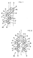
- FIG 1 a first key 40 in accordance with the invention, said key having a shaft 41 made up of a guide region 42 running along the back edge of the key and a blade portion 43.
- the guide region 42 is thus arranged offset to the longitudinal central plane A of the blade portion 43.
- the inside surface F of the blade portion 43 is formed with a rib portion 11' flanked by two grooves 8, 9 arranged one above the other, such that the groove 9 lies at a smaller distance to the narrow edge 10 of the key shaft 41.
- Corresponding to the rib 11' is a groove 11 provided on the outer surface F' of the blade portion 43, while ribs 8', 9' on said surface correspond with the grooves 8, 9.
- the material of the key blade portion is thus substantially uniform (measured normally to the plane A) throughout its length. Viewing figure 1, the grooves 8, 9, 11 are effectively tangential to or intersect the plane A.
- each groove is formed having an arcuate angle, preferably greater than 45°.
- the lateral offset of the plane A to the guide region 42 is such that the extension of the plane C of the side surface 12 of the guide region passes through the peak region S of the rib 11'.
- the extension D of the opposite side surface 12 of the guide region 42 which surface faces away from the plane A, lies at a distance f from the peak region S of the rib 11'. This distance f is greater than the distance e by which the peak region extends beyond the plane A.
- V-cuts are provided in the blade portion 43, along the narrow edge 10 thereof.
- FIG 2 is shown the second key 44 in accordance with the invention.
- This key 44 has two blade portions 45, 46 which lie parallel to one another and are formed integral with each other through a connection with a common guide region 7 via bridging portions 14, 14'.
- the longitudinal central planes A, B of the two blade portions 45, 46 are laterally offset in relation to the guide region 7.
- the side surfaces 12 of the guide region 7, which surfaces face the planes A, B, form an obtuse angle (alpha) with the bridging portions 14, 14'.
- the extension of the plane C of the one side surface 12 passes through the peak region S of the rib 11' of the blade portion 45. Ribs and grooves of this blade portion correspond to that in figure 1 and bear the same reference numerals.
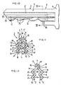
- the third key 2 in accordance with the invention (figures 10 and 11) comprises a key shaft 3 and a handle 4, the shaft 3 again being bifurcated in cross-section.
- the two blade portions 5, 6 forming the fork legs extend from the central guide region 7 and are arranged symmetrically to the longitudinal central plane L-L.
- the longitudinal central planes A, B of the blade portions run parallel to one another so that the guide region 7 lies in the region between these planes A, B, that is to say offset to the planes A, B.
- On the inside surface F of each of the blade portions 5, 6 are two longitudinal grooves 8, 9 which are opposed to one another at the same distance from the narrow edge 10 of the blade portions 5, 6, and between which extends a rib portion 11'.
- Each side surface 12 of the guide region 7 forms an obtuse angle (alpha) with the outer surface 13 of the bridging portion 14 and each blade portion 5, 6, in the narrow edge of which the V-cuts are formed, then itself forms an obtuse angle with the bridging portion 14.
- the key 2 is shown as formed in a single piece.
- the guide region 7 may be composed of two guide region portions 7', 7" lying in a closed formation with one another in such a manner that each guide region portion 7', 7" supports one of the blade portions 5, 6 (see figure 12).
- the closed formation is achieved by the one guide region portion 7" having a groove 18 which is open towards the line of contact 17, into which groove 18 a rib 19 of the other guide region portion 7' is inserted to form a closed shape.
- the two ribs portions can be joined together in the region of the closed formation e.g. by soldering, bonding, welding etc. If it is desired to obtain partner keys, each guide region portion 7', 7" extends into the handle 4.
- the thickness of the guide region 7 corresponds to the thickness of the handle 4.
- the lock cylinder 1 receiving the third key in accordance with the invention has a cylinder housing 19 which is profiled in cross-section.
- a cylinder plug 21 is mounted for rotation in a bore 20 of the housing.
- the plug 21 is in a coupled relationship with a thrower hub 22 which supports a thrower 23 projecting radially.
- In the cylinder housing 19 are provided two rows of bores 24 of non-round cross-section, said rows extending parallel to one another, in which bores 24 tumbler pins 25 are guided, which are located in the housing and correspond with plug pins 26.
- the cylinder plug 21 has corresponding bores 27.
- These pins 25, 26 have a somewhat pear- drop-shaped cross-section for rendering the tumbler pins non-rotational.
- the tumbler pins of the one row are arranged in gaps in relation to the tumbler pins of the other row. Accordingly the V-cuts 15 of the one key blade portions are offset to the V-cuts of the other key blade portion.
- the housing pins 25 are loaded by pin springs 28 so that when no key is inserted in the keyway 29 of the cylinder plug 21, the housing pins 25 cross the shear line G of the cylinder plug 21 and prevent a rotation of the cylinder plug.
- the keyway 29 has a contour which matches the cross-sectional profile of the key 2.
- the outer surface 7"' of the guide region 7 of the key has a round shape corresponding to the way the shear line runs.
- the plug pins 25 In order that, regardless ot the depth of the V-cuts, a secure control of the plug pins 25 is achieved, these latter have a roof-like ridge 30 such that the sloping surfaces lie in the insertion or withdrawal direction of the key.
- the key shaft 3 on the other hand has at its key tip the run-up inclined portion 32 which extends over both blade portions 5, 6.
- the two bridging portions 14 and the guide region 7 run together at the key tip 33.
- a so-called key guide In combination with a funnel-shaped indentation 34 at the front of the plug, a so-called key guide, insertion of the key is facilitated reliably, while at the same time it is centralised in the keyway.
- the appropriate key 2 is inserted into the keyway 29.
- the tumbler pins are so operated that their joint line T lies at the level of the shear line G of the cylinder plug.
- the cylinder plug 21 can then rotate without interruption and move therewith the thrower hub 22.
- each blade portion enables V-cuts of a greater depth than usual to be formed therein and in addition a large number of possible cuts can be made with optimum spacing therebetween. In this way a large number of variations can be achieved without risk.
- the grooves provided on the two blade portions allow optimum profile variation.
- the guide region 7 may also be provided with profiled longitudinal grooves 31.
- the profiles of the blade portion may be formed differently so that the grooves formed therein do not lie at the same level.
- the number of profiled longitudinal grooves of the one blade portion may be different from those of the other.
Description
- This invention is concerned with a key for a cylinder lock comprising a guide region extending along a back edge portion of the key for guiding the key along a keyway of the cylinder, and at least one blade portion having a narrow edge opposite the guide region, in which edge V-cuts are formed for operating tumbler pins of the cylinder, said blade portion also having formed in one side surface thereof at least one longitudinal rib portion flanked at each side by a longitudinal groove.
- Such a key is known from DE-PS 2 551 523, wherein the blade portion is aligned with the guide region. This leads to the possibility of accessing the region of the cylinder accomodating the tumbler pins by means of a picking tool inserted into the keyway which is formed with a relatively large cross-section, in order to operate the tumblers.
- Furthermore a key is disclosed by DE-OS 3 021 128, wherein, as seen in cross-section, an arcuately curved blade portion extends from the guide region. Also in this case the blade portion cannot be regarded as offset from the guide region so that the possibility arises of accessing the look cylinder tumblers by means of a picking tool having a flat form appropriately curved, in order to be able then to operate said tumblers.
- The present invention has its object to provide a relatively simple construction of key wherein, despite the relatively large dimensions of the guide region of the key, and consequently of the keyway, the overall key shape is such that a high protection against picking is ensured.
- This object is resolved, in accordance with the present invention, in a key as set out in the first paragraph above, in that the or each blade portion is connected to the guide region by a bridging portion and the longitudinal central plane of the or each blade portion is offset from that of the guide region such that the side surface of the guide region facing said plane forms an obtuse angle with the bridging portion, and in that an extension of the plane of the side surface of the guide region passes through the peak region of the rib portion(s) formed in the side surface of the blade portion.
- As a result of such construction a key of the type in question is provided with enhanced security value, and indeed without dispensing with a guide region having a relatively large cross sectional dimension. This brings advantages in inserting and withdrawing the key. More particularly, although the guide region, which is of relatively large cross-sectional dimens- tion, allows the insertion of a picking tool into the corresponding region of the keyway, it is very difficult for this to reach the offset region of the keyway corresponding to the blade portion of the key via the obliquely lying intermediate channel which receives the bridging portion. The operation of the lock cylinder tumbler pins is thus effectively prevented. Although the guide region and the longitudinal central plane of the blade portion are offset the keyway region engaged by the blade portion can be shielded , the degree of such shielding depending upon the distance between the projection of the plane of the side surface of the guide region and the peak region of the rib portion. The keyway region engaged by such peak region is likewise accessible only with difficulty by a picking tool.
- Conveniently the grooves flanking the or each rib portion through the peak region of which the extension of the plane of the guide region side surface passes extend beyond the longitudinal central plane of the blade portion. By thus forming the or each blade portion, a large-dimension arcuate portion is provided, which requires a correspondingly shaped portion in the keyway, rendering picking again additionally difficult.
- Such security can indeed be further enhanced, if desired, by the extension of the plane of the opposite side surface of the guide region being spaced from said peak region of the or each rib portion by a distance which is greater than the distance by which such peak region extends beyond the extension of the plane of said one side surface of the guide region.
- An enhanced lock security is achieved by the key comprising two blade portions extending parallel with one another and each being connected to the guide region by a bridging portion as aforesaid. Such an arrangement facilitates an enhanced variation in profile. More particularly more grooves and ribs can be provided on the two blade portions. It is also possible to arrange the height of the blade portions greater than the height of the guide region, so that a greater groove depth for the V-cuts can be achieved. The corresponding lock cylinder then has two rows of tumblers lying parallel with one another. Furthermore, by providing the two grooves adjacent to the rib portion on the inner surface of each of the blade portions, it is also difficult to prepare a copy key. An impression from the inside cannot practically be in any way produced.
- Whereas the two blade portions may be formed integral with a single guide region, alternatively the two blade portions may each have an associated guide region portion with which it is connected by a bridging portion as aforesaid, and the two guide region portions may then be interconnected to form a single guide region having a closed form which can be received in the keyway of the cylinder. In such a case, furthermore, it is possible to extend each guide region portion into a handle so that partner keys can also be produced, e.g. for insertion in bank safes etc. In this case it is a question of two fully effective individual keys.
- Advantageously where two blade portions are provided, they are of the same shape. Thus, opposite the grooves of the one blade portion lie peak regions of the other blade portion. Also with this solution the production of a copy is rendered difficult. Alternatively, the two blade portions may be symmetrical in shape, the plane of symmetry coinciding with the longitudinal central plane of the guide region. Also with this solution the lock variation is comparatively greater than the sum of lock variations of two individual lock cylinders, since the two parts still are related.
- For ease of insertion of the key into the keyway, furthermore, preferably the guide region and the or each blade portion run together at the tip of the key. There now follows a detailed description, to be read with reference to the accompanying drawings, of three keys in accordance with the invention. It will be appreciated that these three keys have been selected for description merely by way of non-limiting example of the invention.
- In the accompanying drawings:
- figure 1 is a cross-section, on a very enlarged scale through a first key in accordance with the invention;
- figure 2 is a cross-section, also on very enlarged scale, through a second key in accordance with the invention;
- figure 3 is a view of a third key in accordance with the invention, together with its associated lock cylinder;
- figure 4 is a plan view of the key and cylinder shown in figure 3;
- figure 5 is a front view, on a very enlarged scale, of the lock cylinder of figures 3 and 4;
- figure 6 is a section along the line Vl-Vl of figure 5;
- figure 7 is a cross-section through the lock cylinder of figure 6, taken in the region of the pin tumbler facing the insertion end;
- figure 8 is a section along the line VIII-VIII of figure 7;
- figure 9 is a cross-section corresponding to figure 7, but with the key inserted;
- figure 10 is a view, on very enlarged scale, of the third key in accordance with the invention;
- figure 11 is a section along the line XI-XI of figure 10; and
- figure 12 is a section representation corresponding to figure 11, but wherein the key is made up of two parts.
- In figure 1 is shown a
first key 40 in accordance with the invention, said key having ashaft 41 made up of aguide region 42 running along the back edge of the key and ablade portion 43. Theguide region 42 is thus arranged offset to the longitudinal central plane A of theblade portion 43. Theside surface 12 of theguide region 42, which surface faces the plane A, forms an obtuse angle (alpha) with abridging portion 14 which connects the guide region andblade portion 43. - The inside surface F of the
blade portion 43 is formed with a rib portion 11' flanked by twogrooves groove 9 lies at a smaller distance to thenarrow edge 10 of thekey shaft 41. Corresponding to the rib 11' is agroove 11 provided on the outer surface F' of theblade portion 43, while ribs 8', 9' on said surface correspond with thegrooves grooves - From figure 1 it can further be seen that the
blade portion 43 lies at an obtuse angle to thebridging portion 14. - The lateral offset of the plane A to the
guide region 42 is such that the extension of the plane C of theside surface 12 of the guide region passes through the peak region S of the rib 11'. The extension D of theopposite side surface 12 of theguide region 42, which surface faces away from the plane A, lies at a distance f from the peak region S of the rib 11'. This distance f is greater than the distance e by which the peak region extends beyond the plane A. - V-cuts are provided in the
blade portion 43, along thenarrow edge 10 thereof. - In figure 2 is shown the
second key 44 in accordance with the invention. Thiskey 44 has twoblade portions 45, 46 which lie parallel to one another and are formed integral with each other through a connection with acommon guide region 7 viabridging portions 14, 14'. In this case also the longitudinal central planes A, B of the twoblade portions 45, 46 are laterally offset in relation to theguide region 7. In addition, theside surfaces 12 of theguide region 7, which surfaces face the planes A, B, form an obtuse angle (alpha) with thebridging portions 14, 14'. Also the extension of the plane C of the oneside surface 12 passes through the peak region S of the rib 11' of theblade portion 45. Ribs and grooves of this blade portion correspond to that in figure 1 and bear the same reference numerals. - The extension of the plane C' of the
opposite side surface 12 on the other hand passes through the peak regions S', S" of the ribs 8' and 9' of the other blade portion 46, since the ribs and grooves of the twoblade portions 45, 46 run parallel to one another, and the two planes A, B are spaced at the same distance from the longitudinal central plane L-L of theguide region 7. - The
third key 2 in accordance with the invention (figures 10 and 11) comprises akey shaft 3 and ahandle 4, theshaft 3 again being bifurcated in cross-section. Thus, the twoblade portions central guide region 7 and are arranged symmetrically to the longitudinal central plane L-L. Furthermore, the longitudinal central planes A, B of the blade portions run parallel to one another so that theguide region 7 lies in the region between these planes A, B, that is to say offset to the planes A, B. On the inside surface F of each of theblade portions longitudinal grooves narrow edge 10 of theblade portions blade portions groove 11. Consequently, it will be appreciated, thegrooves groove 11. - Each side surface 12 of the
guide region 7 forms an obtuse angle (alpha) with theouter surface 13 of the bridgingportion 14 and eachblade portion portion 14. - In addition, the extension of the planes C, C' of each of the side surfaces of the guide region passes through the peak region S of each of the rib portions 11', which lie opposite one another.
- In figure 11 the
key 2 is shown as formed in a single piece. Alternatively theguide region 7 may be composed of twoguide region portions 7', 7" lying in a closed formation with one another in such a manner that eachguide region portion 7', 7" supports one of theblade portions 5, 6 (see figure 12). The closed formation is achieved by the oneguide region portion 7" having agroove 18 which is open towards the line ofcontact 17, into which groove 18 arib 19 of the other guide region portion 7' is inserted to form a closed shape. For the purpose of obtaining a one- piece key the two ribs portions can be joined together in the region of the closed formation e.g. by soldering, bonding, welding etc. If it is desired to obtain partner keys, eachguide region portion 7', 7" extends into thehandle 4. As can be seen especially from figure 4, the thickness of theguide region 7 corresponds to the thickness of thehandle 4. - The lock cylinder 1 receiving the third key in accordance with the invention has a
cylinder housing 19 which is profiled in cross-section. Acylinder plug 21 is mounted for rotation in abore 20 of the housing. Theplug 21 is in a coupled relationship with athrower hub 22 which supports athrower 23 projecting radially. In thecylinder housing 19 are provided two rows ofbores 24 of non-round cross-section, said rows extending parallel to one another, in which bores 24 tumbler pins 25 are guided, which are located in the housing and correspond with plug pins 26. For the latter thecylinder plug 21 has correspondingbores 27. Thesepins cuts 15 of the one key blade portions are offset to the V-cuts of the other key blade portion. The housing pins 25 are loaded by pin springs 28 so that when no key is inserted in thekeyway 29 of thecylinder plug 21, thehousing pins 25 cross the shear line G of thecylinder plug 21 and prevent a rotation of the cylinder plug. Thekeyway 29 has a contour which matches the cross-sectional profile of thekey 2. Furthermore, theouter surface 7"' of theguide region 7 of the key has a round shape corresponding to the way the shear line runs. - In order that, regardless ot the depth of the V-cuts, a secure control of the plug pins 25 is achieved, these latter have a roof-
like ridge 30 such that the sloping surfaces lie in the insertion or withdrawal direction of the key. Thekey shaft 3 on the other hand has at its key tip the run-upinclined portion 32 which extends over bothblade portions bridging portions 14 and theguide region 7 run together at thekey tip 33. In combination with a funnel-shapedindentation 34 at the front of the plug, a so-called key guide, insertion of the key is facilitated reliably, while at the same time it is centralised in the keyway. - When the lock cylinder 1 is to be operated, the
appropriate key 2 is inserted into thekeyway 29. By the V-cuts provided in thenarrow edges 10 the tumbler pins are so operated that their joint line T lies at the level of the shear line G of the cylinder plug. Thecylinder plug 21 can then rotate without interruption and move therewith thethrower hub 22. - From the cross-sectional illustrations of the key it is clear that the height of each blade portion enables V-cuts of a greater depth than usual to be formed therein and in addition a large number of possible cuts can be made with optimum spacing therebetween. In this way a large number of variations can be achieved without risk. Furthermore, the grooves provided on the two blade portions allow optimum profile variation. Similarly, as is indicated in chain- dot in figure 11, the
guide region 7 may also be provided with profiled longitudinal grooves 31. - Alternatively, as illustrated, the profiles of the blade portion may be formed differently so that the grooves formed therein do not lie at the same level. In addition, the number of profiled longitudinal grooves of the one blade portion may be different from those of the other.
Claims (9)
Priority Applications (1)
| Application Number | Priority Date | Filing Date | Title |
|---|---|---|---|
| AT86309169T ATE39530T1 (en) | 1985-11-27 | 1986-11-25 | KEY FOR A LOCK CYLINDER. |
Applications Claiming Priority (4)
| Application Number | Priority Date | Filing Date | Title |
|---|---|---|---|
| DE3541928 | 1985-11-27 | ||
| DE3541928 | 1985-11-27 | ||
| DE19863614222 DE3614222A1 (en) | 1985-11-27 | 1986-04-26 | KEY FOR LOCKING CYLINDER |
| DE3614222 | 1986-04-26 |
Publications (2)
| Publication Number | Publication Date |
|---|---|
| EP0231599A1 EP0231599A1 (en) | 1987-08-12 |
| EP0231599B1 true EP0231599B1 (en) | 1988-12-28 |
Family
ID=25838233
Family Applications (1)
| Application Number | Title | Priority Date | Filing Date |
|---|---|---|---|
| EP19860309169 Expired EP0231599B1 (en) | 1985-11-27 | 1986-11-25 | Key for a lock cylinder |
Country Status (9)
| Country | Link |
|---|---|
| US (1) | US4787225A (en) |
| EP (1) | EP0231599B1 (en) |
| JP (1) | JPH0747900B2 (en) |
| AU (1) | AU585097B2 (en) |
| CA (1) | CA1270124A (en) |
| DE (2) | DE3614222A1 (en) |
| DK (1) | DK163887C (en) |
| ES (1) | ES2006689B3 (en) |
| HK (1) | HK40389A (en) |
Families Citing this family (30)
| Publication number | Priority date | Publication date | Assignee | Title |
|---|---|---|---|---|
| DE4000179A1 (en) * | 1990-01-05 | 1991-07-11 | Bks Gmbh | KEY FOR LOCKING CYLINDERS, ESPECIALLY OF LOCKING SYSTEMS |
| USD327632S (en) | 1991-03-29 | 1992-07-07 | Best Lock Corporation | Portion of a key blade blank |
| US5136869A (en) * | 1991-03-29 | 1992-08-11 | Best Lock Corporation | High security key and cylinder lock assembly |
| US5272895A (en) * | 1991-03-29 | 1993-12-28 | Best Lock Corporation | High security key and cylinder lock assembly |
| USD327412S (en) | 1991-03-29 | 1992-06-30 | Best Lock Corporation | Portion of a key blade blank |
| US5176015A (en) * | 1991-04-10 | 1993-01-05 | Sussina Stan J | Restricted key system |
| DE4123378C3 (en) * | 1991-07-15 | 1997-09-11 | Bab Ikon Gmbh | Cylinder lock for locking systems |
| SE502017C2 (en) * | 1992-07-06 | 1995-07-17 | Widen And Sandh Key Partners A | Cylinder lock-key combination, key for such combination, key blank for making such key and cylinder lock for inclusion in the combination |
| DE4237341C2 (en) * | 1992-11-05 | 1994-08-11 | Bab Ikon Gmbh Schliestechnik | Lock key training |
| AT405858B (en) * | 1994-09-13 | 1999-12-27 | Winkhaus Fa August | Profiled key shank body |
| DE4432571B4 (en) * | 1994-09-13 | 2005-07-07 | Aug. Winkhaus Gmbh & Co. Kg | Flat key shank |
| US5819567A (en) * | 1996-07-19 | 1998-10-13 | International Security Products, Inc. | Lock system with key trapping |
| US5823030A (en) * | 1997-01-29 | 1998-10-20 | International Security Products, Inc. | Cylinder lock system |
| NL1007788C2 (en) * | 1997-12-13 | 1999-06-15 | Holland Agent Beheer B V | Dual pattern key for cylinder lock |
| DE10042070C2 (en) * | 2000-08-08 | 2002-09-26 | Ikon Ag | Lock and key system |
| US6615628B2 (en) * | 2001-07-20 | 2003-09-09 | Chi-Wen Lou | Picklock-proof key slot for a lock device and a key thereof |
| DE10324205B3 (en) * | 2003-05-28 | 2004-10-21 | Dom-Sicherheitstechnik Gmbh & Co. Kg | Cylinder for a lock comprises a key with a highly profiled rib having control tracks arranged next to each other in the key insertion direction |
| DE10353465A1 (en) * | 2003-11-15 | 2005-07-07 | Aug. Winkhaus Gmbh & Co. Kg | Key for a lock cylinder having two parallel rows of pin tumblers |
| US7174757B1 (en) * | 2005-10-17 | 2007-02-13 | Yuan-Cheng Tseng | Lock cylinder and key set |
| DE102006000123A1 (en) * | 2006-03-17 | 2007-09-20 | Aug. Winkhaus Gmbh & Co. Kg | Key for a lock cylinder |
| US7353675B1 (en) * | 2006-09-18 | 2008-04-08 | Sheng-Ho Chao | Lock barrel and a driving part for the same |
| US8950226B2 (en) * | 2011-10-12 | 2015-02-10 | Moshe Dolev | Cylinder lock assembly with non-rotating elements |
| WO2013169760A1 (en) | 2012-05-08 | 2013-11-14 | Schlage Lock Company Llc | Variable section key and lock |
| CN103397820B (en) * | 2013-08-16 | 2015-07-08 | 陈小仁 | Hidden anti-theft lock cylinder and opening key |
| CA2972279C (en) * | 2015-01-13 | 2020-11-03 | Bowley Lock Company Inc. | High security locking system which forms a deviating picking path and associated deviated key |
| DE102018101438A1 (en) * | 2018-01-23 | 2019-07-25 | Assa Abloy Sicherheitstechnik Gmbh | Flat key profile for a lock and key system |
| AT523800B1 (en) * | 2020-05-12 | 2022-06-15 | Evva Sicherheitstechnologie | Cross-sectional profile for a flat key or the keyway of a cylinder lock |
| US11542724B1 (en) | 2022-08-22 | 2023-01-03 | Winloc Ag | Key blank, a key, and a cylinder lock and key combination |
| US11536047B1 (en) | 2022-08-22 | 2022-12-27 | Winloc Ag | Key plug, a cylinder lock, a cylinder lock and key combination and a method to manufacture a key plug |
| US11613909B1 (en) | 2022-08-22 | 2023-03-28 | Winloc Ag | Key blank, a coded key and a cylinder lock and key system with improved stop arrangement |
Family Cites Families (22)
| Publication number | Priority date | Publication date | Assignee | Title |
|---|---|---|---|---|
| US1564883A (en) * | 1923-05-25 | 1925-12-08 | James A Muzzio | Cylinder lock |
| US1832498A (en) * | 1928-06-11 | 1931-11-17 | Rosa S Muzzio | Tumbler lock and key therefor |
| US2049548A (en) * | 1933-08-16 | 1936-08-04 | Gunnard E Swanson | Lock |
| US2006374A (en) * | 1934-04-12 | 1935-07-02 | Herman W Voges | Lock operating means |
| GB517655A (en) * | 1938-08-09 | 1940-02-05 | Harold Gilbert Ramsell | Improvements relating to pin-tumbler cylinder locks and keys therefor |
| CH255045A (en) * | 1946-12-16 | 1948-06-15 | Ebosa Sa | Safety lock. |
| DE810956C (en) * | 1948-01-12 | 1951-08-16 | Smw Sueddeutsche Mechanische W | Cylinder lock |
| US2620649A (en) * | 1948-02-18 | 1952-12-09 | Bernardo Vicente Santo Domingo | Pin tumbler lock |
| DE1186776B (en) * | 1964-02-07 | 1965-02-04 | Voss Kg J | Group key |
| US3492842A (en) * | 1967-08-25 | 1970-02-03 | Schlage Lock Co | Lock cylinder unit |
| JPS5028360B2 (en) * | 1973-07-27 | 1975-09-13 | ||
| DE2433918C2 (en) * | 1974-07-15 | 1986-06-05 | DOM-Sicherheitstechnik GmbH & Co KG, 5040 Brühl | Flat key for a lock cylinder |
| DE7536474U (en) * | 1975-11-17 | 1976-04-01 | Eaton Gmbh, 5620 Velbert | GROUP KEYS FOR ROTARY CYLINDER LOCKS OF LOCKING SYSTEMS, IN PARTICULAR MAIN KEY SYSTEMS |
| DE2551523C3 (en) * | 1975-11-17 | 1982-03-18 | Scovill Sicherheitseinrichtungen Gmbh, 5620 Velbert | Group flat key for rotary cylinder locks in locking systems |
| AT340802B (en) * | 1976-01-28 | 1978-01-10 | Evva Werke | KEY-LOCK COMBINATION |
| DE3021128C2 (en) * | 1980-06-04 | 1987-02-12 | C. Ed. Schulte GmbH, 5628 Velbert | Cylinder lock for locking systems |
| US4498327A (en) * | 1981-03-30 | 1985-02-12 | Taboola Pty. Ltd. | Cylinder locks and keys therefor |
| JPS57201472A (en) * | 1981-03-30 | 1982-12-09 | Tabuura Pty Ltd | Barrel and key of cylinder lock |
| BR8104814A (en) * | 1981-04-08 | 1983-03-01 | Noel Litvin | DRUM LOCK BILATERAL KEY |
| NZ206292A (en) * | 1982-11-23 | 1986-07-11 | M E F Strassmeir | Cylinder lock assembly:individual locking pins arranged in one or more rows engage adjacent row of tumbler pins transverse to longitudinal axis of tumbler pins |
| DE3340073A1 (en) * | 1983-11-05 | 1984-03-08 | Zeiss Ikon Ag, 7000 Stuttgart | LOCK-KEY SYSTEM, ESPECIALLY FOR LOCKING SYSTEMS |
| IT1176242B (en) * | 1984-06-01 | 1987-08-18 | Italiana Serrature Affini | STRUCTURED CYLINDER LOCK KEY TO PREVENT BURGLARS |
-
1986
- 1986-04-26 DE DE19863614222 patent/DE3614222A1/en active Granted
- 1986-11-18 US US06/932,468 patent/US4787225A/en not_active Expired - Lifetime
- 1986-11-25 CA CA000523792A patent/CA1270124A/en not_active Expired - Fee Related
- 1986-11-25 ES ES86309169T patent/ES2006689B3/en not_active Expired - Lifetime
- 1986-11-25 DE DE8686309169T patent/DE3661561D1/en not_active Expired
- 1986-11-25 EP EP19860309169 patent/EP0231599B1/en not_active Expired
- 1986-11-26 DK DK567586A patent/DK163887C/en active
- 1986-11-26 AU AU65694/86A patent/AU585097B2/en not_active Ceased
- 1986-11-27 JP JP28301186A patent/JPH0747900B2/en not_active Expired - Lifetime
-
1989
- 1989-05-18 HK HK40389A patent/HK40389A/en not_active IP Right Cessation
Also Published As
| Publication number | Publication date |
|---|---|
| DK567586A (en) | 1987-05-28 |
| DE3614222A1 (en) | 1987-06-04 |
| DE3661561D1 (en) | 1989-02-02 |
| JPS62133265A (en) | 1987-06-16 |
| HK40389A (en) | 1989-05-26 |
| AU585097B2 (en) | 1989-06-08 |
| CA1270124A (en) | 1990-06-12 |
| DK567586D0 (en) | 1986-11-26 |
| EP0231599A1 (en) | 1987-08-12 |
| DK163887C (en) | 1992-09-14 |
| US4787225A (en) | 1988-11-29 |
| DE3614222C2 (en) | 1988-10-06 |
| JPH0747900B2 (en) | 1995-05-24 |
| ES2006689B3 (en) | 1994-03-01 |
| AU6569486A (en) | 1987-06-04 |
| DK163887B (en) | 1992-04-13 |
Similar Documents
| Publication | Publication Date | Title |
|---|---|---|
| EP0231599B1 (en) | Key for a lock cylinder | |
| US4116025A (en) | Reversible flat key for cylinder locks | |
| EP0237172B1 (en) | Locking device consisting of a locking cylinder and associated flat key | |
| KR101005095B1 (en) | Key blank, key and master keying system | |
| US4393673A (en) | Cylinder lock | |
| US5131249A (en) | Key for a cylinder lock, especially for locking systems | |
| RO118028B1 (en) | Cylinder lock with a profiled key | |
| US4343166A (en) | Cylinder lock with associated flat key | |
| CA1046300A (en) | Reversible-flat key for a cylinder lock | |
| US4964288A (en) | Locking device and reversible key | |
| CA2492088C (en) | Safety key and locking cylinder, and locking system with such safety keys and locking cylinders | |
| RO118029B1 (en) | Cylinder lock with profiled key and profiled key therefor | |
| JPH0135992B2 (en) | ||
| KR910012479A (en) | Lock cylinder, key and key blank with safety lock | |
| US5287712A (en) | Locking arrangement consisting of key and lock cylinder | |
| CA1096650A (en) | Pickproof lock | |
| SK284385B6 (en) | Flat key for cylinder lock | |
| CZ281010B6 (en) | Cylindrical lock with a flat key | |
| US10443265B2 (en) | Set of profile members in combination with a key plug, a method to manufacture such a key plug and a combination also including an associated key | |
| GB2064637A (en) | Cylinder Lock |
Legal Events
| Date | Code | Title | Description |
|---|---|---|---|
| PUAI | Public reference made under article 153(3) epc to a published international application that has entered the european phase |
Free format text: ORIGINAL CODE: 0009012 |
|
| AK | Designated contracting states |
Kind code of ref document: A1 Designated state(s): AT BE CH DE ES FR GB IT LI LU NL SE |
|
| 17P | Request for examination filed |
Effective date: 19870901 |
|
| 17Q | First examination report despatched |
Effective date: 19880303 |
|
| GRAA | (expected) grant |
Free format text: ORIGINAL CODE: 0009210 |
|
| AK | Designated contracting states |
Kind code of ref document: B1 Designated state(s): AT BE CH DE ES FR GB IT LI LU NL SE |
|
| REF | Corresponds to: |
Ref document number: 39530 Country of ref document: AT Date of ref document: 19890115 Kind code of ref document: T |
|
| REF | Corresponds to: |
Ref document number: 3661561 Country of ref document: DE Date of ref document: 19890202 |
|
| ET | Fr: translation filed | ||
| ITF | It: translation for a ep patent filed |
Owner name: UFFICIO BREVETTI RICCARDI & C. |
|
| PLBE | No opposition filed within time limit |
Free format text: ORIGINAL CODE: 0009261 |
|
| STAA | Information on the status of an ep patent application or granted ep patent |
Free format text: STATUS: NO OPPOSITION FILED WITHIN TIME LIMIT |
|
| 26N | No opposition filed | ||
| ITTA | It: last paid annual fee | ||
| EPTA | Lu: last paid annual fee | ||
| EAL | Se: european patent in force in sweden |
Ref document number: 86309169.0 |
|
| PGFP | Annual fee paid to national office [announced via postgrant information from national office to epo] |
Ref country code: FR Payment date: 20001101 Year of fee payment: 15 |
|
| PGFP | Annual fee paid to national office [announced via postgrant information from national office to epo] |
Ref country code: DE Payment date: 20001102 Year of fee payment: 15 |
|
| PGFP | Annual fee paid to national office [announced via postgrant information from national office to epo] |
Ref country code: NL Payment date: 20001103 Year of fee payment: 15 Ref country code: GB Payment date: 20001103 Year of fee payment: 15 Ref country code: CH Payment date: 20001103 Year of fee payment: 15 Ref country code: AT Payment date: 20001103 Year of fee payment: 15 |
|
| PGFP | Annual fee paid to national office [announced via postgrant information from national office to epo] |
Ref country code: SE Payment date: 20001106 Year of fee payment: 15 |
|
| PGFP | Annual fee paid to national office [announced via postgrant information from national office to epo] |
Ref country code: LU Payment date: 20001115 Year of fee payment: 15 |
|
| PGFP | Annual fee paid to national office [announced via postgrant information from national office to epo] |
Ref country code: BE Payment date: 20001127 Year of fee payment: 15 |
|
| PGFP | Annual fee paid to national office [announced via postgrant information from national office to epo] |
Ref country code: ES Payment date: 20001211 Year of fee payment: 15 |
|
| PG25 | Lapsed in a contracting state [announced via postgrant information from national office to epo] |
Ref country code: LU Free format text: LAPSE BECAUSE OF NON-PAYMENT OF DUE FEES Effective date: 20011125 Ref country code: GB Free format text: LAPSE BECAUSE OF NON-PAYMENT OF DUE FEES Effective date: 20011125 Ref country code: AT Free format text: LAPSE BECAUSE OF NON-PAYMENT OF DUE FEES Effective date: 20011125 |
|
| PG25 | Lapsed in a contracting state [announced via postgrant information from national office to epo] |
Ref country code: SE Free format text: LAPSE BECAUSE OF NON-PAYMENT OF DUE FEES Effective date: 20011126 Ref country code: ES Free format text: LAPSE BECAUSE OF NON-PAYMENT OF DUE FEES Effective date: 20011126 |
|
| PG25 | Lapsed in a contracting state [announced via postgrant information from national office to epo] |
Ref country code: LI Free format text: LAPSE BECAUSE OF NON-PAYMENT OF DUE FEES Effective date: 20011130 Ref country code: CH Free format text: LAPSE BECAUSE OF NON-PAYMENT OF DUE FEES Effective date: 20011130 Ref country code: BE Free format text: LAPSE BECAUSE OF NON-PAYMENT OF DUE FEES Effective date: 20011130 |
|
| REG | Reference to a national code |
Ref country code: GB Ref legal event code: IF02 |
|
| BERE | Be: lapsed |
Owner name: DOM-SICHERHEITSTECHNIK G.M.B.H. & CO. K.G. Effective date: 20011130 |
|
| PG25 | Lapsed in a contracting state [announced via postgrant information from national office to epo] |
Ref country code: NL Free format text: LAPSE BECAUSE OF NON-PAYMENT OF DUE FEES Effective date: 20020601 |
|
| EUG | Se: european patent has lapsed |
Ref document number: 86309169.0 |
|
| PG25 | Lapsed in a contracting state [announced via postgrant information from national office to epo] |
Ref country code: DE Free format text: LAPSE BECAUSE OF NON-PAYMENT OF DUE FEES Effective date: 20020702 |
|
| REG | Reference to a national code |
Ref country code: CH Ref legal event code: PL |
|
| GBPC | Gb: european patent ceased through non-payment of renewal fee |
Effective date: 20011125 |
|
| PG25 | Lapsed in a contracting state [announced via postgrant information from national office to epo] |
Ref country code: FR Free format text: LAPSE BECAUSE OF NON-PAYMENT OF DUE FEES Effective date: 20020730 |
|
| NLV4 | Nl: lapsed or anulled due to non-payment of the annual fee |
Effective date: 20020601 |
|
| REG | Reference to a national code |
Ref country code: FR Ref legal event code: ST |
|
| REG | Reference to a national code |
Ref country code: FR Ref legal event code: ST |
|
| REG | Reference to a national code |
Ref country code: ES Ref legal event code: FD2A Effective date: 20021213 |
|
| PG25 | Lapsed in a contracting state [announced via postgrant information from national office to epo] |
Ref country code: IT Free format text: LAPSE BECAUSE OF NON-PAYMENT OF DUE FEES Effective date: 20051125 |