EP0231554B1 - Transmission projection screen and method of manufacturing same - Google Patents
Transmission projection screen and method of manufacturing same Download PDFInfo
- Publication number
- EP0231554B1 EP0231554B1 EP86202351A EP86202351A EP0231554B1 EP 0231554 B1 EP0231554 B1 EP 0231554B1 EP 86202351 A EP86202351 A EP 86202351A EP 86202351 A EP86202351 A EP 86202351A EP 0231554 B1 EP0231554 B1 EP 0231554B1
- Authority
- EP
- European Patent Office
- Prior art keywords
- screen
- grooves
- light
- synthetic resin
- glass
- Prior art date
- Legal status (The legal status is an assumption and is not a legal conclusion. Google has not performed a legal analysis and makes no representation as to the accuracy of the status listed.)
- Expired
Links
Images
Classifications
-
- G—PHYSICS
- G03—PHOTOGRAPHY; CINEMATOGRAPHY; ANALOGOUS TECHNIQUES USING WAVES OTHER THAN OPTICAL WAVES; ELECTROGRAPHY; HOLOGRAPHY
- G03B—APPARATUS OR ARRANGEMENTS FOR TAKING PHOTOGRAPHS OR FOR PROJECTING OR VIEWING THEM; APPARATUS OR ARRANGEMENTS EMPLOYING ANALOGOUS TECHNIQUES USING WAVES OTHER THAN OPTICAL WAVES; ACCESSORIES THEREFOR
- G03B21/00—Projectors or projection-type viewers; Accessories therefor
- G03B21/54—Accessories
- G03B21/56—Projection screens
- G03B21/60—Projection screens characterised by the nature of the surface
- G03B21/62—Translucent screens
- G03B21/625—Lenticular translucent screens
Definitions
- the invention relates to a method of manufacturing a transmission projection screen as claimed in claim 1, comprising a transparent substrate having a front surface which is provided with parallel ribs from which light issues during operation of the screen, the ribs being separated by grooves in which light-absorbing filaments are disposed.
- Such a screen is used, for example, for displaying images or alphanumeric data which are projected onto the rear surface of the screen, for example, by a lens system with one or more cathode ray tubes or by a film projector.
- the transparent ribs on the front surface of the screen focus the light rays which are received from the rear side and which issue via the crests of the ribs.
- the grooves between the ribs remain dark.
- a light-absorbing material is disposed in the grooves. It is known for this purpose to apply a black lacquer layer or to dispose black particles in the grooves.
- a disadvantage of such screens is the high degree of mechanical contact and, therefore optical contact between the ribs and the light-absorbing material, which causes light that should be reflected on the inside of the walls of the ribs to be absorbed, thereby reducing the light output of the screen.
- United States Patent Specification US 4525029 describes a transmission projection screen and a method of manufacturing such a screen, in which method black wires for example, of yarn, metal or synthetic resin are introduced into the grooves.
- the black wires are inserted longitudinally into the grooves, and during and/or after insertion the wires are tautened to make sure that they lie in the grooves over their full length.
- the wires are fixed by means of, for example, adhesive.
- a disadvantage of such a screen is that it may be subject to warping, for example, due to changing ambient conditions, humidity being a particularly important factor.
- a further object of the invention is to provide a transmission projection screen having an aesthetically attractive, smooth front surface.
- a particular object of the invention is to provide a transmission projection screen having a flat or substantially flat front surface, the light-absorbing filament lying deeply in the grooves over their full length so as not to catch the light issuing from the crests of the ribs.
- glass fibres Due to the great rigidity of glass, glass fibres can be inserted deeply into the grooves over their full length without being having to be tautened. The use of glass fibres results in an aesthetically attractive screen having straight and regular light-absorbing lines.
- the surfaces of the glass fibre may be provided with, for example, a black layer.
- the glass fibres consist of black glass.
- the use of glass fibres has the additional advantage that the diameter of a glass fibre may be chosen within wide limits and may be adapted to the cross-sectional dimensions of the grooves in order to make sure that the glass fibre fits in the lower part of a groove, whilst having a sufficiently large diameter to substantially reduce the light reflection at the front side of the screen.
- An additional object of the invention is to provide a method of manufacturing a transmission projection screen, in which the light-absorbing filaments can be readily fixed in the grooves.
- Such a treatment may consist in, for example, contacting the screen with the vapour of a solvent for the synthetic resin of the synthetic resin cladding.
- the treatment whereby the synthetic resin cladding is made to adhere to the walls of the grooves is a heat treatment.
- the synthetic resin cladding consists of an adhesive whose adhesive action is obtained by heating and subsequent cooling, a so-called "hot-melt" adhesive.
- An important advantage of this embodiment of the method is that glass fibres may be used which are provided with a synthetic resin cladding in separate treatment and which at some later time, for example after storage, are used in the actual manufacture of the screen, which is usually carried out in a clean room. Consequently, chemicals such ad adhesive, solvents or black powdered material for providing the grooves of the projection screen with light-absorbing material do not have to be used in the clean room.
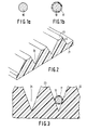
- Figures 1a and 1b are sectional views of a glass fibre respectively without and with a synthetic resin cladding, which fibre is suitable for use in a screen in accordance with the invention
- Figure 2 is a perspective sectional view of part of a substrate provided with ribs, for use in a screen in accordance with the invention
- Figure 3 is a sectional view of part of a screen in accordance with the invention, a glass fibre being shown in one of the grooves.
- a glass fibre is manufactured in a way which is known per se , for example, by drawing from a preform or from molten glass contained in a crucible which has a discharge opening at the bottom.
- the glass composition is so selected that the glass fibre has a black colour.
- a suitable glass composition comprises, for example, 60.2% by weight of SiO2, 16.8 % by weight of B203, 7.5 % by weight of K20, 3.3 % by weight of Al203, 0.4 % by weight of Na20, 0.8 % by weight of Li20, 2.7 % by weight of V2O5 and 8.3 % by weight of Fe203, which glass composition can be drawn from a preform into a fibre at a temperature of 675 °C.
- the cross-section of the fibre may have any suitable shape, provided that it is selected so that the area of contact of the fibre with the wall of the groove into which it is subsequently inserted is small.
- a fibre having a circular cross-section is used (see Figure 1a).
- the diameter of the fibre is such, for example, 100 ⁇ m in the present example, that the fibre can be disposed at the bottom of the grooves.
- a glass fibre 10 is shown whose entire surface is clad with a layer 11 of a polyamide, for example, Eurelon 2140 ® , which is marketed by Schering.
- the thickness of the cladding is 10 ⁇ m.
- the fibre may be only partially clad, for example, on one side, with such a layer.
- the polyamide is applied in a solution which contains 25 % by weight of polyamide in a solvent which consists of 65 % by weight of n-propanol, 20% by weight of toluene and 15 % by weight of water.
- the solution is applied by means of low-pressure extrusion after which the glass fibre is fed through an oven at a temperature of 200 °C which causes the solvent to evaporate, leaving a polyamide layer on the glass fibre.
- Figure 2 shows part of a substrate 21, for example, of polymethylmethacryalte, provided with parallel ribs 22 on its front surface.
- the screen shown in the drawing is flat, but the invention may also be applied to a slightly curved screen.
- the ribs 22 are provided at their crest with a lens structure 23. However, dependent upon the desired optical characteristic of the screen, the crests of the ribs may have various shapes.
- the ribs 22 are separated by groove 24 of V-shaped cross-section.
- the ribs and the grooves may be formed on the surface of the substrate by means of, for example, a replication technique which is known per se , from for example, a synthetic resin composition which can be cured by UV light.
- the rear surface of the substrate may also be provided with an optical element, for example, a fresnel structure.
- an optical element for example, a fresnel structure.
- the pitch of the parallel grooves i.e. the distance between the adjacent grooves at their deepest points is 275 ⁇ m, and the depth of the grooves is 440 ⁇ m.
- Figure 3 is a sectional view of a glass fibre 10 which has a synthetic resin cladding 11 and which is located at the bottom of one of the V-section grooves 24.
- the synthetic resin is heated to a temperature of 180 °C for a short time, for example 1 minute, and subsequently cooled to room temperature.
- the heating is carried out by, for example, radiation having a wavelength such that the radiation is absorbed by the black glass fibres but not by the transparent substrate.
- the bond between the glass fibres and the walls of the grooves is formed.
- a reflective layer may be applied to the walls of the grooves in order to facilitate the internal reflection of the light in the ribs.
- the light-absorbing glass fibres are bonded to the rear surface of the reflective layer.
- a screen manufactured in accordance with the method described herein has an attractive appearance and is evenly blackened.
- the black bands are resistant to wear and to rubbing and cleaning using cleaning agents.
- the glass fibres impart a greater rigidity to the screen which is resistant to the action of moisture, such that, in particular, the tendency of the screen to warp is reduced.
Landscapes
- Physics & Mathematics (AREA)
- General Physics & Mathematics (AREA)
- Overhead Projectors And Projection Screens (AREA)
Applications Claiming Priority (2)
| Application Number | Priority Date | Filing Date | Title |
|---|---|---|---|
| NL8600043 | 1986-01-10 | ||
| NL8600043A NL8600043A (nl) | 1986-01-10 | 1986-01-10 | Doorzicht projectiescherm en werkwijze voor de vervaardiging daarvan. |
Publications (2)
| Publication Number | Publication Date |
|---|---|
| EP0231554A1 EP0231554A1 (en) | 1987-08-12 |
| EP0231554B1 true EP0231554B1 (en) | 1991-06-26 |
Family
ID=19847401
Family Applications (1)
| Application Number | Title | Priority Date | Filing Date |
|---|---|---|---|
| EP86202351A Expired EP0231554B1 (en) | 1986-01-10 | 1986-12-22 | Transmission projection screen and method of manufacturing same |
Country Status (7)
| Country | Link |
|---|---|
| US (1) | US4682853A (da) |
| EP (1) | EP0231554B1 (da) |
| JP (2) | JPS62164033A (da) |
| CA (1) | CA1270677A (da) |
| DE (1) | DE3679981D1 (da) |
| DK (1) | DK167258B1 (da) |
| NL (1) | NL8600043A (da) |
Families Citing this family (13)
| Publication number | Priority date | Publication date | Assignee | Title |
|---|---|---|---|---|
| EP0511721A3 (en) * | 1987-10-06 | 1992-11-25 | Koninklijke Philips Electronics N.V. | Front projection screen with reflected light concentrating lens array |
| US4964695A (en) * | 1987-10-06 | 1990-10-23 | North American Philips Corporation | Lenticular arrays for front projection screens and contrast improving method and device |
| US4927233A (en) * | 1989-03-06 | 1990-05-22 | Mitsubishi Rayon Co., Ltd. | Rear projection screen |
| US5121252A (en) * | 1990-05-11 | 1992-06-09 | Mitsubishi Rayon Co., Ltd. | Projection screen and method for producing the same |
| US5481385A (en) * | 1993-07-01 | 1996-01-02 | Alliedsignal Inc. | Direct view display device with array of tapered waveguide on viewer side |
| US5563738A (en) * | 1993-09-03 | 1996-10-08 | Jenmar Visual Systems | Light transmitting and dispersing filter having low reflectance |
| US5521726A (en) * | 1994-08-26 | 1996-05-28 | Alliedsignal Inc. | Polarizer with an array of tapered waveguides |
| US5657408A (en) * | 1994-12-23 | 1997-08-12 | Alliedsignal Inc. | Optical device comprising a plurality of units having at least two geometrically-differentiated tapered optical waveguides therein |
| US6010747A (en) * | 1996-12-02 | 2000-01-04 | Alliedsignal Inc. | Process for making optical structures for diffusing light |
| US6600599B2 (en) | 1998-06-09 | 2003-07-29 | Avery Dennison Corporation | Rear projection screens and light filters with conformable coatings and methods of making the same |
| US6597417B1 (en) * | 2000-07-25 | 2003-07-22 | Scram Technologies, Inc. | Optical panel having black material between apexes of serrations on the inlet face |
| US7453634B2 (en) * | 2005-03-07 | 2008-11-18 | Avery Dennison Corporation | Discontinuous or variable thickness gain modification coating for projection film and method for making same |
| KR101209399B1 (ko) * | 2007-05-22 | 2012-12-06 | 최해용 | 바닥용 영사 스크린 및 그 제조방법 |
Family Cites Families (2)
| Publication number | Priority date | Publication date | Assignee | Title |
|---|---|---|---|---|
| JPS59121034A (ja) * | 1982-12-27 | 1984-07-12 | Mitsubishi Rayon Co Ltd | 透過型スクリ−ン |
| JPS6079342A (ja) * | 1983-10-07 | 1985-05-07 | Mitsubishi Rayon Co Ltd | 透過型スクリ−ン |
-
1986
- 1986-01-10 NL NL8600043A patent/NL8600043A/nl not_active Application Discontinuation
- 1986-03-26 US US06/844,051 patent/US4682853A/en not_active Expired - Fee Related
- 1986-12-22 EP EP86202351A patent/EP0231554B1/en not_active Expired
- 1986-12-22 DE DE8686202351T patent/DE3679981D1/de not_active Expired - Lifetime
-
1987
- 1987-01-07 DK DK006687A patent/DK167258B1/da not_active IP Right Cessation
- 1987-01-07 CA CA000526821A patent/CA1270677A/en not_active Expired
- 1987-01-08 JP JP62001140A patent/JPS62164033A/ja active Pending
-
1995
- 1995-03-17 JP JP002059U patent/JPH0744839U/ja active Pending
Also Published As
| Publication number | Publication date |
|---|---|
| DK6687D0 (da) | 1987-01-07 |
| EP0231554A1 (en) | 1987-08-12 |
| JPH0744839U (ja) | 1995-11-28 |
| CA1270677A (en) | 1990-06-26 |
| DK167258B1 (da) | 1993-09-27 |
| DK6687A (da) | 1987-07-11 |
| JPS62164033A (ja) | 1987-07-20 |
| US4682853A (en) | 1987-07-28 |
| DE3679981D1 (de) | 1991-08-01 |
| NL8600043A (nl) | 1987-08-03 |
Similar Documents
| Publication | Publication Date | Title |
|---|---|---|
| EP0231554A1 (en) | Transmission projection screen and method of manufacturing same | |
| US5183323A (en) | Flat panel illumination system | |
| JP6564352B2 (ja) | ビデオスクリーンカバーガラス照明 | |
| US5021928A (en) | Flat panel illumination system | |
| US3907403A (en) | Fibre-optics faceplate observable with high-intensity ambient illumination | |
| US3141106A (en) | Image transmitting screen | |
| EP0114395B1 (en) | Rear projection screen | |
| US6487350B1 (en) | Multi-clad black display panel | |
| CN100405216C (zh) | 透射式投影屏及使用该投影屏的透射式投影显示装置 | |
| EP1342111A4 (en) | HIGH CONTRAST FRONT PANJECTION DISPLAY AND METHOD OF PRODUCTION THEREOF | |
| US4573082A (en) | Focusable display screen | |
| US4591232A (en) | Optical display screen utilizing light-absorbing fibers | |
| US4688093A (en) | Transmission projection screen and method of manufacturing same | |
| JP2749156B2 (ja) | 反射形スクリーン及びこれを用いた表示装置 | |
| CN1318767A (zh) | 反射型画面照明装置 | |
| US4743090A (en) | Screen assembly for electromagnetic radiation | |
| US4697881A (en) | Anti-glare filter | |
| EP0231553B1 (en) | Transmission projection screen and method of manufacturing same | |
| JPH10282315A (ja) | 光拡散板およびその製造方法 | |
| JPS63165838A (ja) | 透過型スクリ−ン | |
| JPS58216235A (ja) | 透過型投影スクリ−ン | |
| JP2943388B2 (ja) | レンチキュラーレンズシートの製造方法と製造装置 | |
| EP0304517B1 (en) | Anti-glare filter | |
| JPS59182430A (ja) | 背面投影スクリ−ン | |
| JPS58216234A (ja) | 透過型投影スクリ−ン用レンズ板 |
Legal Events
| Date | Code | Title | Description |
|---|---|---|---|
| PUAI | Public reference made under article 153(3) epc to a published international application that has entered the european phase |
Free format text: ORIGINAL CODE: 0009012 |
|
| AK | Designated contracting states |
Kind code of ref document: A1 Designated state(s): DE FR GB IT NL SE |
|
| 17P | Request for examination filed |
Effective date: 19880204 |
|
| 17Q | First examination report despatched |
Effective date: 19900625 |
|
| GRAA | (expected) grant |
Free format text: ORIGINAL CODE: 0009210 |
|
| AK | Designated contracting states |
Kind code of ref document: B1 Designated state(s): DE FR GB IT NL SE |
|
| PG25 | Lapsed in a contracting state [announced via postgrant information from national office to epo] |
Ref country code: NL Effective date: 19910626 Ref country code: SE Effective date: 19910626 Ref country code: IT Free format text: LAPSE BECAUSE OF FAILURE TO SUBMIT A TRANSLATION OF THE DESCRIPTION OR TO PAY THE FEE WITHIN THE PRE;WARNING: LAPSES OF ITALIAN PATENTS WITH EFFECTIVE DATE BEFORE 2007 MAY HAVE OCCURRED AT ANY TIME BEFORE 2007. THE CORRECT EFFECTIVE DATE MAY BE DIFFERENT FROM THE ONE RECORDED.SCRIBED TIME-LIMIT Effective date: 19910626 |
|
| REF | Corresponds to: |
Ref document number: 3679981 Country of ref document: DE Date of ref document: 19910801 |
|
| ET | Fr: translation filed | ||
| NLV1 | Nl: lapsed or annulled due to failure to fulfill the requirements of art. 29p and 29m of the patents act | ||
| PLBE | No opposition filed within time limit |
Free format text: ORIGINAL CODE: 0009261 |
|
| STAA | Information on the status of an ep patent application or granted ep patent |
Free format text: STATUS: NO OPPOSITION FILED WITHIN TIME LIMIT |
|
| 26N | No opposition filed | ||
| PGFP | Annual fee paid to national office [announced via postgrant information from national office to epo] |
Ref country code: FR Payment date: 19921222 Year of fee payment: 7 |
|
| PGFP | Annual fee paid to national office [announced via postgrant information from national office to epo] |
Ref country code: DE Payment date: 19930224 Year of fee payment: 7 |
|
| PGFP | Annual fee paid to national office [announced via postgrant information from national office to epo] |
Ref country code: GB Payment date: 19931210 Year of fee payment: 8 |
|
| PG25 | Lapsed in a contracting state [announced via postgrant information from national office to epo] |
Ref country code: FR Effective date: 19940831 |
|
| PG25 | Lapsed in a contracting state [announced via postgrant information from national office to epo] |
Ref country code: DE Effective date: 19940901 |
|
| REG | Reference to a national code |
Ref country code: FR Ref legal event code: ST |
|
| PG25 | Lapsed in a contracting state [announced via postgrant information from national office to epo] |
Ref country code: GB Effective date: 19941222 |
|
| GBPC | Gb: european patent ceased through non-payment of renewal fee |
Effective date: 19941222 |