EP0230933A1 - A core setter - Google Patents
A core setter Download PDFInfo
- Publication number
- EP0230933A1 EP0230933A1 EP87100556A EP87100556A EP0230933A1 EP 0230933 A1 EP0230933 A1 EP 0230933A1 EP 87100556 A EP87100556 A EP 87100556A EP 87100556 A EP87100556 A EP 87100556A EP 0230933 A1 EP0230933 A1 EP 0230933A1
- Authority
- EP
- European Patent Office
- Prior art keywords
- core
- swingable arm
- retaining means
- mould
- moulding chamber
- Prior art date
- Legal status (The legal status is an assumption and is not a legal conclusion. Google has not performed a legal analysis and makes no representation as to the accuracy of the status listed.)
- Granted
Links
- 238000000465 moulding Methods 0.000 claims abstract description 33
- 230000007246 mechanism Effects 0.000 description 3
- 239000004576 sand Substances 0.000 description 3
- 238000000034 method Methods 0.000 description 2
- 230000000712 assembly Effects 0.000 description 1
- 238000000429 assembly Methods 0.000 description 1
- 238000011065 in-situ storage Methods 0.000 description 1
- 239000000463 material Substances 0.000 description 1
Images

Classifications
-
- B—PERFORMING OPERATIONS; TRANSPORTING
- B22—CASTING; POWDER METALLURGY
- B22C—FOUNDRY MOULDING
- B22C9/00—Moulds or cores; Moulding processes
- B22C9/10—Cores; Manufacture or installation of cores
- B22C9/108—Installation of cores
-
- B—PERFORMING OPERATIONS; TRANSPORTING
- B22—CASTING; POWDER METALLURGY
- B22C—FOUNDRY MOULDING
- B22C11/00—Moulding machines characterised by the relative arrangement of the parts of same
- B22C11/10—Moulding machines characterised by the relative arrangement of the parts of same with one or more flasks forming part of the machine, from which only the sand moulds made by compacting are removed
Definitions
- the invention relates to a core setter for use in placinq one or more cores in the mould impression in the rearmost of a number of mould parts or in the mould impression on the front of the subsequent mould part during conveyance from the moulding chamber, such mould part having been made in a vertical moulding system and during conveyance towards a pouring line.
- a wide range of assemblies and mechanisms are known which are designed for moving cores more or less automatically from a loading position outside the moulding plant behind the mould parts made, and from the said position transferrinq the cores from a retaining means to the mould impressions.
- the known devices are in many cases constructed on a frame which is placed as an independent unit alongside the mouldina system in a complex way and takes up much room.
- the known devices are as a rule designed with columnar guides placed at right angles to each other, whereby core setting is made along an L-shaped path.
- the two vertical columnar q uides give "loose" steering with the consequent problems in relation to imprecise positioning of the cores in the mould impressions. Precision can be achieved by suitable dimensioning and working of the columnar guides used, but this is an expensive procedure.
- the object of the invention is to provide a simplified core- setting mechanism, which takes up very little room, and which - by its simplicity of structure - provides great precision in positioning the core retainer in relation to the mould impressions.
- a core setter of the type described in the opening paragraph characterized by the setter comprising an essentially L-shaped swingable arm, at its one end pivotably journalled around a vertical axis, and at its other end designed to accept a core-retaining means, whereby the swingable arm can be swung between a core-releasing position, in which the core-retaining means is placed behind the rearmost mould part and in line with it, and a loading position outside the line of mould parts, and that means are provided to convey the core-retaining means translationally towards and away from the mould impression in the releasing position.
- the L-shaped swingable arm ensures a very high rigidity in the moving mechanism, as the one bearing point and the swingable arm form a rigid structure without linear columnar guides, as is otherwise known from the L-guides referred to above. Any play can be limited to that part of the movement where the core-retaining means is conveyed translationally forwards on bearing guides towards the mould impression.
- the swingable arm is pivotably journalled around a pivot secured on the moulding chamber
- the means for providing the translational movement of the core-retaining means is a cylinder piston unit inserted between the swingable arm and the core-retaining means, said core-retaining means being suspended on the swingable arm and guided in at least two bearing guides.
- the swingable arm can be pivotally journalled around a pivot on a slide placed slideably on the moulding chamber structure, whereby the translational movement of the core-retaining means is provided by reciprocating the slide in the longitudinal direction of the moulding chamber.
- This conveying of the swingable arm by the slide outside the chamber permits a quicker working sequence, as the dimensions of the core-retaining means can be minimized, whereby the inertia force of the arm is reduced to a minimum.
- a stop means may be mounted on the moulding chamber structure to limit the pivotal movement of the swingable arm and to control it during the translational feeding of the core-retaining means.
- the L-shaped swingable arm can be cranked with a shape corresponding to fixed obstructions on the moulding chamber structure.
- This embodiment structure makes it possible to use a swingable arm structure, where the outermost portions of the swingable arm are removed as little as possible from the sides of the moulding chamber in the loading position. At the same time, a placement possibility for the pivot point of the swingable arm is achieved, which is independent of the remaining components of the moulding plant.
- the embodiments described above provide the common additional advantage in that the core-retaining means may be swung entirely away from the lead-in area, if cores are not to be used, or if the loading operation takes place more expediently at a greater distance from the machine.
- a further significant feature of the invention is that the core setter may be swung into the core-releasinq position for shipping purposes, so that the machine will arrive ready- mounted to the user.
- the core setter unit has to be packed and shipped separately and the unit must be mounted in situ, which often gives rise to practical problems, and in all circumstances adds to costs.
- the swingable arm is generally shown by the reference number 1.
- the L-shaped swingable arm 1 is pivotally journalled around a vertical axis 2 above the moulding chamber 3 in a machine (not shown in more detail) for making mould parts of sand or other like mouldable material.
- yoke 4 In front of the moulding chamber 3 there is a foremost yoke 4, which, as indicated by the dot-and-dash lines, can be reciprocated lenghtwise in the moulding chamber between a position (solid lines), in which the swingable plate, pivotally suspended from the yoke, forms a mould limitation face in the moulding chamber, and a position (dot- and-dash lines), in which the yoke is free from the moulding chamber, and the swingable plate has been swung up, so that the mould parts 5 made in the moulding chamber 3 can be shot out of the latter.
- the swingable arm 1 consists of two sections, 6 and 7, of which the former is designed to pivot around the pivot 2 and support the second section 7 in such a way that the latter is swung in between the rearmost mould part 5 and the moulding chamber 3 in front of the said yoke 4 in its squeeze position by pivoting around the pivot.2.
- the part 7 supports two columns 8, on which a core mask 10 is provided for reciprocatina by actuation of a cylinder piston unit 9.
- the cores in the core mask 10 can be fed into the mould impression in the mould part 5 in a manner known per se.
- the movement of the swingable arm is controlled by the cylinder piston unit 12, which connects with the swingable arm via a link connection 13. In the swung-in position, the swingable arm is fixed by abutting one or more stops 11.
- the core mask 10 can be designed so as to move against the direction of travel of the mould parts, whereby the cores are placed in the last mould part in process of being transported away from the moulding chamber.
- the swingable arm 1 is seen from the side in its swung-in position behind the mould part 5.
- a sand container 15 is conventionally placed above the moulding chamber 3; from this container the moulding sand is shot into the moulding chamber 3.
- the invention is not limited to precisely the depicted and described features, and hence it will be possible to make use of a slide mounted on the moulding chamber structure, which supports the pivot 2, and in such a way that the translational movement of the core mask 10 is provided by reciprocating the slide in relation to the chamber structure.
Abstract
Description
- The invention relates to a core setter for use in placinq one or more cores in the mould impression in the rearmost of a number of mould parts or in the mould impression on the front of the subsequent mould part during conveyance from the moulding chamber, such mould part having been made in a vertical moulding system and during conveyance towards a pouring line.
- A wide range of assemblies and mechanisms are known which are designed for moving cores more or less automatically from a loading position outside the moulding plant behind the mould parts made, and from the said position transferrinq the cores from a retaining means to the mould impressions.
- The known devices are in many cases constructed on a frame which is placed as an independent unit alongside the mouldina system in a complex way and takes up much room. In addition, the known devices are as a rule designed with columnar guides placed at right angles to each other, whereby core setting is made along an L-shaped path. The two vertical columnar quides give "loose" steering with the consequent problems in relation to imprecise positioning of the cores in the mould impressions. Precision can be achieved by suitable dimensioning and working of the columnar guides used, but this is an expensive procedure.
- The object of the invention is to provide a simplified core- setting mechanism, which takes up very little room, and which - by its simplicity of structure - provides great precision in positioning the core retainer in relation to the mould impressions.
- According to the invention, this is achieved by a core setter of the type described in the opening paragraph, characterized by the setter comprising an essentially L-shaped swingable arm, at its one end pivotably journalled around a vertical axis, and at its other end designed to accept a core-retaining means, whereby the swingable arm can be swung between a core-releasing position, in which the core-retaining means is placed behind the rearmost mould part and in line with it, and a loading position outside the line of mould parts, and that means are provided to convey the core-retaining means translationally towards and away from the mould impression in the releasing position.
- The L-shaped swingable arm ensures a very high rigidity in the moving mechanism, as the one bearing point and the swingable arm form a rigid structure without linear columnar guides, as is otherwise known from the L-guides referred to above. Any play can be limited to that part of the movement where the core-retaining means is conveyed translationally forwards on bearing guides towards the mould impression.
- In a possible embodiment of a core setter accordinq to the invention, the swingable arm is pivotably journalled around a pivot secured on the moulding chamber, and the means for providing the translational movement of the core-retaining means is a cylinder piston unit inserted between the swingable arm and the core-retaining means, said core-retaining means being suspended on the swingable arm and guided in at least two bearing guides.
- Thus, accurate and easily controllable movement of the core-retaining means during core delivery is obtained by simple means.
- In another embodiment, the swingable arm can be pivotally journalled around a pivot on a slide placed slideably on the moulding chamber structure, whereby the translational movement of the core-retaining means is provided by reciprocating the slide in the longitudinal direction of the moulding chamber. This conveying of the swingable arm by the slide outside the chamber permits a quicker working sequence, as the dimensions of the core-retaining means can be minimized, whereby the inertia force of the arm is reduced to a minimum.
- By placing the vertical pivot axis of the swingable arm, as proposed according to the invention, in the vertical symmetrical plane of the moulding chamber, a lead-in path is achieved with the flattest possible lead-in sequence, and thus the opportunity to operate with the largest possible core height at given dimensions, in particular the distance between the moulding chamber and the rearmost mould part.
- According to the invention, a stop means may be mounted on the moulding chamber structure to limit the pivotal movement of the swingable arm and to control it during the translational feeding of the core-retaining means.
- This ensures even greater precision during the translational portion of the movement of the core-retaining means, and in particular great precision in the core delivery moment.
- According to the invention, the L-shaped swingable arm can be cranked with a shape corresponding to fixed obstructions on the moulding chamber structure.
- This embodiment structure makes it possible to use a swingable arm structure, where the outermost portions of the swingable arm are removed as little as possible from the sides of the moulding chamber in the loading position. At the same time, a placement possibility for the pivot point of the swingable arm is achieved, which is independent of the remaining components of the moulding plant.
- The embodiments described above provide the common additional advantage in that the core-retaining means may be swung entirely away from the lead-in area, if cores are not to be used, or if the loading operation takes place more expediently at a greater distance from the machine.
- A further significant feature of the invention is that the core setter may be swung into the core-releasinq position for shipping purposes, so that the machine will arrive ready- mounted to the user. In known systems, the core setter unit has to be packed and shipped separately and the unit must be mounted in situ, which often gives rise to practical problems, and in all circumstances adds to costs.
- Below, the invention will be explained in detail with reference to the drawing, in which
- fig. 1 is a schematic view of a core setter according to the invention, seen from above, and
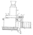
- fig. 2 is the same in a schematic vertical section.
- In fig. 1, the swingable arm is generally shown by the reference number 1. The L-shaped swingable arm 1 is pivotally journalled around a
vertical axis 2 above themoulding chamber 3 in a machine (not shown in more detail) for making mould parts of sand or other like mouldable material. - In front of the
moulding chamber 3 there is a foremost yoke 4, which, as indicated by the dot-and-dash lines, can be reciprocated lenghtwise in the moulding chamber between a position (solid lines), in which the swingable plate, pivotally suspended from the yoke, forms a mould limitation face in the moulding chamber, and a position (dot- and-dash lines), in which the yoke is free from the moulding chamber, and the swingable plate has been swung up, so that themould parts 5 made in themoulding chamber 3 can be shot out of the latter. - The swingable arm 1 consists of two sections, 6 and 7, of which the former is designed to pivot around the
pivot 2 and support thesecond section 7 in such a way that the latter is swung in between therearmost mould part 5 and themoulding chamber 3 in front of the said yoke 4 in its squeeze position by pivoting around the pivot.2. - In the shown embodiment, the
part 7 supports twocolumns 8, on which acore mask 10 is provided for reciprocatina by actuation of a cylinder piston unit 9. - When the swingable arm 1 has thus been swung in behind the
mould part 5, the cores in thecore mask 10 can be fed into the mould impression in themould part 5 in a manner known per se. - The movement of the swingable arm is controlled by the
cylinder piston unit 12, which connects with the swingable arm via alink connection 13. In the swung-in position, the swingable arm is fixed by abutting one ormore stops 11. - It should be noted that the
core mask 10 can be designed so as to move against the direction of travel of the mould parts, whereby the cores are placed in the last mould part in process of being transported away from the moulding chamber. - In fig. 2, the swingable arm 1 is seen from the side in its swung-in position behind the
mould part 5. - In fig. 2, the parts corresponding to those shown in fig. 1, are designated by the same reference numbers.
- A
sand container 15 is conventionally placed above themoulding chamber 3; from this container the moulding sand is shot into themoulding chamber 3. - The invention is not limited to precisely the depicted and described features, and hence it will be possible to make use of a slide mounted on the moulding chamber structure, which supports the
pivot 2, and in such a way that the translational movement of thecore mask 10 is provided by reciprocating the slide in relation to the chamber structure.
Claims (6)
Priority Applications (1)
| Application Number | Priority Date | Filing Date | Title |
|---|---|---|---|
| AT87100556T ATE45896T1 (en) | 1986-01-24 | 1987-01-16 | CORE LOADING DEVICE. |
Applications Claiming Priority (2)
| Application Number | Priority Date | Filing Date | Title |
|---|---|---|---|
| DK373/86 | 1986-01-24 | ||
| DK037386A DK37386A (en) | 1986-01-24 | 1986-01-24 | core setter |
Publications (2)
| Publication Number | Publication Date |
|---|---|
| EP0230933A1 true EP0230933A1 (en) | 1987-08-05 |
| EP0230933B1 EP0230933B1 (en) | 1989-08-30 |
Family
ID=8092778
Family Applications (1)
| Application Number | Title | Priority Date | Filing Date |
|---|---|---|---|
| EP87100556A Expired EP0230933B1 (en) | 1986-01-24 | 1987-01-16 | A core setter |
Country Status (12)
| Country | Link |
|---|---|
| US (1) | US4765389A (en) |
| EP (1) | EP0230933B1 (en) |
| JP (1) | JPS62173210A (en) |
| CN (1) | CN1005690B (en) |
| AT (1) | ATE45896T1 (en) |
| BR (1) | BR8700322A (en) |
| DE (1) | DE3760493D1 (en) |
| DK (1) | DK37386A (en) |
| ES (1) | ES2010509B3 (en) |
| GR (1) | GR3000214T3 (en) |
| IN (1) | IN164736B (en) |
| SU (1) | SU1561817A3 (en) |
Cited By (1)
| Publication number | Priority date | Publication date | Assignee | Title |
|---|---|---|---|---|
| EP2718040B1 (en) | 2011-06-13 | 2017-04-19 | Componenta Oyj | Arrangement and method for moulds for metal casting |
Families Citing this family (11)
| Publication number | Priority date | Publication date | Assignee | Title |
|---|---|---|---|---|
| DK241689A (en) * | 1989-05-18 | 1990-11-19 | Dansk Ind Syndikat | PROCEDURE AND APPARATUS FOR THE REPLACEMENT OF CORE MACHINES BY A CORE EQUIPMENT FOR AN AUTOMATIC FORMING PLANT |
| DE19621294A1 (en) * | 1996-05-25 | 1997-11-27 | Holger Buetzler | Automatic core insertion equipment for sand moulding machines |
| ES2199005B1 (en) * | 1999-06-09 | 2005-04-01 | Georg Fischer Disa A/S. | METHOD OF CONSTRUCTION OF THE OSCILLATING PLATE SUPPORT SYSTEM IN A CONTINUOUS COLADA MOLDING MACHINE BY FOUNDING IN SAND AND CONTINUOUS COLLAR MOLDING MACHINE WITH OSCILLATING PLATE SUPPORT SYSTEM ACCORDING TO SAID METHOD. |
| US6868894B2 (en) * | 2000-11-30 | 2005-03-22 | Disa Industries A/S | Core setter for matchplate moulding machine |
| US20080185117A1 (en) * | 2007-10-11 | 2008-08-07 | Sintokogio, Ltd. | A core-setting apparatus used for a molding apparatus and a method for setting a core |
| CN102151801A (en) * | 2010-11-16 | 2011-08-17 | 苏州苏铸成套装备制造有限公司 | Moving-out and coring device |
| CN102228958B (en) * | 2011-07-01 | 2012-10-10 | 满城县永红铸造机械有限公司 | Core feeding machine |
| ES2823161T3 (en) * | 2013-05-21 | 2021-05-06 | Loramendi S Coop | Sand Mold Making Machine |
| CN103551525B (en) * | 2013-11-03 | 2015-08-05 | 衢州乐创节能科技有限公司 | A kind of internal mold assembly machine |
| EP3283248B1 (en) * | 2015-04-17 | 2018-12-12 | Disa Industries A/S | Method and system for indexing moulds |
| JP6443422B2 (en) * | 2016-10-14 | 2018-12-26 | トヨタ自動車株式会社 | Core gripping device |
Citations (5)
| Publication number | Priority date | Publication date | Assignee | Title |
|---|---|---|---|---|
| FR1437239A (en) * | 1965-06-18 | 1966-04-29 | Wallwork & Co Ltd Henry | Method and apparatus for placing foundry cores in molds |
| US3300823A (en) * | 1965-03-01 | 1967-01-31 | Altamil Corp | Mold assembly and pouring method and apparatus |
| US3424229A (en) * | 1966-02-22 | 1969-01-28 | Dansk Ind Syndikat | Core insertion unit for casting moulds |
| US3910343A (en) * | 1974-08-16 | 1975-10-07 | Alexei Ivanovich Popov | Device for placing cores into removable-flask moulds |
| US4079774A (en) * | 1973-06-25 | 1978-03-21 | Dansk Industri Syndikat A/S | System for making sand molds each having associated therewith a core member |
Family Cites Families (7)
| Publication number | Priority date | Publication date | Assignee | Title |
|---|---|---|---|---|
| US3168765A (en) * | 1962-03-21 | 1965-02-09 | Canada Iron Foundries Ltd | Automatic core setters for centrifugal pipe casting machines |
| GB1057548A (en) * | 1964-06-19 | 1967-02-01 | Henry Wallwork And Company Ltd | Cored foundry moulds |
| JPS522690B2 (en) * | 1973-08-22 | 1977-01-24 | ||
| JPS5223849A (en) * | 1975-08-18 | 1977-02-23 | Kurita Water Ind Ltd | Water treatment apparatus |
| SU564091A1 (en) * | 1976-03-24 | 1977-07-05 | Минский Филиал Научно-Исследовательского Института Технологии Автомобильной Промышленности | Device for installation,drawing out and movement of upper metal core |
| JPS59189058A (en) * | 1983-04-11 | 1984-10-26 | Ube Ind Ltd | Method and device for loading insert |
| US4590982A (en) * | 1984-12-11 | 1986-05-27 | Hunter William A | Automatic core setting machine |
-
1986
- 1986-01-24 DK DK037386A patent/DK37386A/en not_active Application Discontinuation
- 1986-02-28 JP JP61042023A patent/JPS62173210A/en active Granted
- 1986-03-27 CN CN86101959.8A patent/CN1005690B/en not_active Expired
-
1987
- 1987-01-16 ES ES87100556T patent/ES2010509B3/en not_active Expired
- 1987-01-16 EP EP87100556A patent/EP0230933B1/en not_active Expired
- 1987-01-16 AT AT87100556T patent/ATE45896T1/en not_active IP Right Cessation
- 1987-01-16 DE DE8787100556T patent/DE3760493D1/en not_active Expired
- 1987-01-21 US US07/005,723 patent/US4765389A/en not_active Expired - Lifetime
- 1987-01-22 IN IN69/CAL/87A patent/IN164736B/en unknown
- 1987-01-23 SU SU874028905A patent/SU1561817A3/en active
- 1987-01-26 BR BR8700322A patent/BR8700322A/en unknown
-
1989
- 1989-11-15 GR GR89400243T patent/GR3000214T3/en unknown
Patent Citations (5)
| Publication number | Priority date | Publication date | Assignee | Title |
|---|---|---|---|---|
| US3300823A (en) * | 1965-03-01 | 1967-01-31 | Altamil Corp | Mold assembly and pouring method and apparatus |
| FR1437239A (en) * | 1965-06-18 | 1966-04-29 | Wallwork & Co Ltd Henry | Method and apparatus for placing foundry cores in molds |
| US3424229A (en) * | 1966-02-22 | 1969-01-28 | Dansk Ind Syndikat | Core insertion unit for casting moulds |
| US4079774A (en) * | 1973-06-25 | 1978-03-21 | Dansk Industri Syndikat A/S | System for making sand molds each having associated therewith a core member |
| US3910343A (en) * | 1974-08-16 | 1975-10-07 | Alexei Ivanovich Popov | Device for placing cores into removable-flask moulds |
Cited By (1)
| Publication number | Priority date | Publication date | Assignee | Title |
|---|---|---|---|---|
| EP2718040B1 (en) | 2011-06-13 | 2017-04-19 | Componenta Oyj | Arrangement and method for moulds for metal casting |
Also Published As
| Publication number | Publication date |
|---|---|
| ES2010509B3 (en) | 1989-11-16 |
| BR8700322A (en) | 1987-12-08 |
| CN1005690B (en) | 1989-11-08 |
| JPS62173210A (en) | 1987-07-30 |
| ATE45896T1 (en) | 1989-09-15 |
| SU1561817A3 (en) | 1990-04-30 |
| DK37386D0 (en) | 1986-01-24 |
| JPH0456700B2 (en) | 1992-09-09 |
| IN164736B (en) | 1989-05-20 |
| DE3760493D1 (en) | 1989-10-05 |
| EP0230933B1 (en) | 1989-08-30 |
| GR3000214T3 (en) | 1990-12-31 |
| US4765389A (en) | 1988-08-23 |
| CN86101959A (en) | 1987-08-05 |
| DK37386A (en) | 1987-07-25 |
Similar Documents
| Publication | Publication Date | Title |
|---|---|---|
| EP0230933A1 (en) | A core setter | |
| US5901774A (en) | Linear mold handling system with double-deck pouring and cooling lines | |
| US3424229A (en) | Core insertion unit for casting moulds | |
| EP0818291A1 (en) | Insert molding method and apparatus therefor | |
| US6145577A (en) | Linear mold handling system | |
| JP2006315058A (en) | Mold clamping device for die-casting machine, mold changing method using the mold clamping device, and changing system of moving side die plate | |
| JP3145964B2 (en) | Low pressure die casting plant | |
| US3923095A (en) | Apparatus for separating magnetizable castings from casting moulds of sand or similar materials | |
| US3999594A (en) | Apparatus for producing casting moulds consisting of identical mould parts | |
| EP2001275A1 (en) | Apparatus and method for separating electronic components | |
| US4037731A (en) | Workpiece transport apparatus | |
| US4079774A (en) | System for making sand molds each having associated therewith a core member | |
| US2942718A (en) | Cooling system for foundry molds | |
| ES383980A1 (en) | Automatically operated multiple cavity die for low-pressure chill-casting | |
| CN209937516U (en) | Automatic glue feeder for mould | |
| US5758710A (en) | Apparatus for inserting a part into a foundry core to be completed to a core assembly | |
| JPS6254724B2 (en) | ||
| CN111842866B (en) | Casting device and casting system | |
| CN217920107U (en) | Automatic ceramic valve core placing machine capable of achieving quick feeding | |
| JPS62230536A (en) | Film transporter of fixed format | |
| WO1982001506A1 (en) | Mould sorting table | |
| US4547212A (en) | Take-out mechanism for a glassware forming machine | |
| US3284861A (en) | Jolt de-sanding machine for mould flasks | |
| SU1734923A1 (en) | Method for production of foundry auxiliaries | |
| CN116652114A (en) | Core handling device |
Legal Events
| Date | Code | Title | Description |
|---|---|---|---|
| PUAI | Public reference made under article 153(3) epc to a published international application that has entered the european phase |
Free format text: ORIGINAL CODE: 0009012 |
|
| 17P | Request for examination filed |
Effective date: 19870212 |
|
| AK | Designated contracting states |
Kind code of ref document: A1 Designated state(s): AT BE CH DE ES FR GB GR IT LI LU NL SE |
|
| 17Q | First examination report despatched |
Effective date: 19880428 |
|
| GRAA | (expected) grant |
Free format text: ORIGINAL CODE: 0009210 |
|
| AK | Designated contracting states |
Kind code of ref document: B1 Designated state(s): AT BE CH DE ES FR GB GR IT LI LU NL SE |
|
| REF | Corresponds to: |
Ref document number: 45896 Country of ref document: AT Date of ref document: 19890915 Kind code of ref document: T |
|
| ITF | It: translation for a ep patent filed |
Owner name: ING. A. GIAMBROCONO & C. S.R.L. |
|
| REF | Corresponds to: |
Ref document number: 3760493 Country of ref document: DE Date of ref document: 19891005 |
|
| ET | Fr: translation filed | ||
| PGFP | Annual fee paid to national office [announced via postgrant information from national office to epo] |
Ref country code: SE Payment date: 19891214 Year of fee payment: 4 |
|
| PGFP | Annual fee paid to national office [announced via postgrant information from national office to epo] |
Ref country code: LU Payment date: 19891220 Year of fee payment: 4 Ref country code: BE Payment date: 19891220 Year of fee payment: 4 |
|
| PGFP | Annual fee paid to national office [announced via postgrant information from national office to epo] |
Ref country code: CH Payment date: 19891221 Year of fee payment: 4 |
|
| PGFP | Annual fee paid to national office [announced via postgrant information from national office to epo] |
Ref country code: GR Payment date: 19891229 Year of fee payment: 4 |
|
| PGFP | Annual fee paid to national office [announced via postgrant information from national office to epo] |
Ref country code: AT Payment date: 19900125 Year of fee payment: 4 |
|
| PG25 | Lapsed in a contracting state [announced via postgrant information from national office to epo] |
Ref country code: LU Free format text: LAPSE BECAUSE OF NON-PAYMENT OF DUE FEES Effective date: 19900131 |
|
| PGFP | Annual fee paid to national office [announced via postgrant information from national office to epo] |
Ref country code: NL Payment date: 19900131 Year of fee payment: 4 |
|
| PLBE | No opposition filed within time limit |
Free format text: ORIGINAL CODE: 0009261 |
|
| STAA | Information on the status of an ep patent application or granted ep patent |
Free format text: STATUS: NO OPPOSITION FILED WITHIN TIME LIMIT |
|
| REG | Reference to a national code |
Ref country code: GR Ref legal event code: FG4A Free format text: 3000214 |
|
| 26N | No opposition filed | ||
| PG25 | Lapsed in a contracting state [announced via postgrant information from national office to epo] |
Ref country code: AT Effective date: 19910116 |
|
| PG25 | Lapsed in a contracting state [announced via postgrant information from national office to epo] |
Ref country code: SE Effective date: 19910117 |
|
| ITTA | It: last paid annual fee | ||
| PG25 | Lapsed in a contracting state [announced via postgrant information from national office to epo] |
Ref country code: LI Effective date: 19910131 Ref country code: CH Effective date: 19910131 Ref country code: BE Effective date: 19910131 |
|
| PG25 | Lapsed in a contracting state [announced via postgrant information from national office to epo] |
Ref country code: GR Free format text: THE PATENT HAS BEEN ANNULLED BY A DECISION OF A NATIONAL AUTHORITY Effective date: 19910731 |
|
| PG25 | Lapsed in a contracting state [announced via postgrant information from national office to epo] |
Ref country code: NL Effective date: 19910801 |
|
| NLV4 | Nl: lapsed or anulled due to non-payment of the annual fee | ||
| REG | Reference to a national code |
Ref country code: CH Ref legal event code: PL |
|
| PGFP | Annual fee paid to national office [announced via postgrant information from national office to epo] |
Ref country code: FR Payment date: 19931210 Year of fee payment: 8 |
|
| PGFP | Annual fee paid to national office [announced via postgrant information from national office to epo] |
Ref country code: GB Payment date: 19940106 Year of fee payment: 8 |
|
| PGFP | Annual fee paid to national office [announced via postgrant information from national office to epo] |
Ref country code: ES Payment date: 19940118 Year of fee payment: 8 |
|
| REG | Reference to a national code |
Ref country code: GR Ref legal event code: MM2A Free format text: 3000214 |
|
| PG25 | Lapsed in a contracting state [announced via postgrant information from national office to epo] |
Ref country code: GB Effective date: 19950116 |
|
| PG25 | Lapsed in a contracting state [announced via postgrant information from national office to epo] |
Ref country code: ES Free format text: LAPSE BECAUSE OF NON-PAYMENT OF DUE FEES Effective date: 19950117 |
|
| EUG | Se: european patent has lapsed |
Ref document number: 87100556.7 Effective date: 19910910 |
|
| GBPC | Gb: european patent ceased through non-payment of renewal fee |
Effective date: 19950116 |
|
| PG25 | Lapsed in a contracting state [announced via postgrant information from national office to epo] |
Ref country code: FR Effective date: 19950929 |
|
| REG | Reference to a national code |
Ref country code: FR Ref legal event code: ST |
|
| REG | Reference to a national code |
Ref country code: ES Ref legal event code: FD2A Effective date: 19990201 |
|
| PGFP | Annual fee paid to national office [announced via postgrant information from national office to epo] |
Ref country code: DE Payment date: 20040225 Year of fee payment: 18 |
|
| PG25 | Lapsed in a contracting state [announced via postgrant information from national office to epo] |
Ref country code: IT Free format text: LAPSE BECAUSE OF NON-PAYMENT OF DUE FEES;WARNING: LAPSES OF ITALIAN PATENTS WITH EFFECTIVE DATE BEFORE 2007 MAY HAVE OCCURRED AT ANY TIME BEFORE 2007. THE CORRECT EFFECTIVE DATE MAY BE DIFFERENT FROM THE ONE RECORDED. Effective date: 20050116 |
|
| PG25 | Lapsed in a contracting state [announced via postgrant information from national office to epo] |
Ref country code: DE Free format text: LAPSE BECAUSE OF NON-PAYMENT OF DUE FEES Effective date: 20050802 |