EP0230833B1 - Leuchte für Fahrzeuge mit mehreren Signallampen - Google Patents
Leuchte für Fahrzeuge mit mehreren Signallampen Download PDFInfo
- Publication number
- EP0230833B1 EP0230833B1 EP19860402900 EP86402900A EP0230833B1 EP 0230833 B1 EP0230833 B1 EP 0230833B1 EP 19860402900 EP19860402900 EP 19860402900 EP 86402900 A EP86402900 A EP 86402900A EP 0230833 B1 EP0230833 B1 EP 0230833B1
- Authority
- EP
- European Patent Office
- Prior art keywords
- reflectors
- lighting unit
- unit according
- tongues
- socket
- Prior art date
- Legal status (The legal status is an assumption and is not a legal conclusion. Google has not performed a legal analysis and makes no representation as to the accuracy of the status listed.)
- Expired - Lifetime
Links
- 230000011664 signaling Effects 0.000 title description 9
- 210000002105 tongue Anatomy 0.000 claims description 20
- 230000000295 complement effect Effects 0.000 claims description 5
- 230000009471 action Effects 0.000 claims description 2
- 230000000712 assembly Effects 0.000 description 6
- 238000000429 assembly Methods 0.000 description 6
- 230000005489 elastic deformation Effects 0.000 description 3
- 239000011521 glass Substances 0.000 description 3
- 238000005452 bending Methods 0.000 description 2
- 230000004907 flux Effects 0.000 description 2
- 238000010438 heat treatment Methods 0.000 description 2
- 238000003780 insertion Methods 0.000 description 2
- 230000037431 insertion Effects 0.000 description 2
- 239000002184 metal Substances 0.000 description 2
- 239000004020 conductor Substances 0.000 description 1
- 239000006185 dispersion Substances 0.000 description 1
- 230000000694 effects Effects 0.000 description 1
- 238000009434 installation Methods 0.000 description 1
- 230000014759 maintenance of location Effects 0.000 description 1
- 238000004519 manufacturing process Methods 0.000 description 1
- 239000000463 material Substances 0.000 description 1
- 238000002844 melting Methods 0.000 description 1
- 230000008018 melting Effects 0.000 description 1
- 238000000034 method Methods 0.000 description 1
- 238000000465 moulding Methods 0.000 description 1
- 230000003287 optical effect Effects 0.000 description 1
- 238000013021 overheating Methods 0.000 description 1
- 230000009467 reduction Effects 0.000 description 1
- 238000000926 separation method Methods 0.000 description 1
- 229910000679 solder Inorganic materials 0.000 description 1
- 239000000758 substrate Substances 0.000 description 1
Images
Classifications
-
- B—PERFORMING OPERATIONS; TRANSPORTING
- B60—VEHICLES IN GENERAL
- B60Q—ARRANGEMENT OF SIGNALLING OR LIGHTING DEVICES, THE MOUNTING OR SUPPORTING THEREOF OR CIRCUITS THEREFOR, FOR VEHICLES IN GENERAL
- B60Q1/00—Arrangement of optical signalling or lighting devices, the mounting or supporting thereof or circuits therefor
- B60Q1/26—Arrangement of optical signalling or lighting devices, the mounting or supporting thereof or circuits therefor the devices being primarily intended to indicate the vehicle, or parts thereof, or to give signals, to other traffic
- B60Q1/2607—Arrangement of optical signalling or lighting devices, the mounting or supporting thereof or circuits therefor the devices being primarily intended to indicate the vehicle, or parts thereof, or to give signals, to other traffic comprising at least two indicating lamps
Definitions
- the present invention relates generally to the signaling lights of motor vehicles, and more particularly relates to a signaling light according to the preamble of claim 1, consisting of a set of lamps associated with respective reflective elements, all the lamps contributing obtaining the same light function.
- a signaling light of this type has been devised with the main aim of reducing its depth.
- conventional filament lamps due to the high luminous flux which they bring into play, with consequently a high temperature in the enclosure of the fire, prohibit an excessive reduction in the volume thereof.
- the globe or glass for closing such a fire, made of plastic cannot be brought as close as possible to the lamp, as it risks overheating and melting.
- a motor vehicle signaling light constituted by several lamps of low power and of reduced dimensions can have a very shallow depth, without risk of excessive heating, and a large illuminating surface.
- the present invention aims to overcome the drawbacks of the prior art and to propose a signaling light, for example for a motor vehicle, which comprises simplified means for the electrical connection of the lamps with one another and with an external power source.
- Another object of the invention is to provide a modular structure, with which one can quickly and simply realize a light comprising lamp / reflector assemblies in any number.
- the present invention relates to a signaling light for a vehicle, such as a motor vehicle, of the type comprising a set of lamps, a set of reflectors arranged in at least one row and each comprising a socket for mounting an associated lamp, and means for electrical connection of the lamps with an external power source, characterized in that the electrical connection means comprise, for each row, two conductive bars for the electrical connection in parallel of the lamps of said row with the external power source, each bar comprising a set of flexible projecting tongues engaged in the respective sockets and taking place simultaneously as an electrical contact surface for the electrodes of the lamps and as a means of fixing said bar to the reflectors.
- the reflectors are in the form of individual elements, and on the bars and on adjacent surfaces of the reflectors are provided complementary male / female cooperation means, for example fingers integral with the conductive bars and complementary holes provided in the base surfaces of the reflectors, the bars also ensuring in this way the fixing of the reflectors with respect to each other.
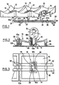
- the light is constituted by three filament lamps (not shown in FIG. 1) associated with three parabolic reflecting elements 10 of rectangular contours.
- the reflectors 10 are initially separated from each other. They will advantageously be obtained by molding plastic material.
- each reflective or reflective element 10 At the center of each reflective or reflective element 10 is formed a socket 12 having a through passage 14 adapted to receive the base of the associated lamp.
- the passage 14 has a section of elongated rectangular shape, to adapt to the base 18 in the form of a thin blade of a filament lamp 16 called "wedge-base" (see FIGS. 2 and 3).
- the passage 14 is delimited by straight walls ending on the side of the reflecting surface (above in FIGS. 1 and 3) by a sharp angle edge.
- Two flat bars 20, 22, of conductive metal, are provided to ensure the electrical connection between the lamps and with an external power source and, simultaneously - in the present example, the mechanical connection of the reflective elements 10 between them.
- the bars 20 and 22 extend parallel to one another and parallel to the rear face (bottom in FIG. 2) of the reflectors.
- Each bar has three flexible contact and fixing tabs 24 extending substantially at right angles to the longitudinal direction of the bar, and regularly spaced with a pitch approximately equal to the width of a reflector 10.
- Each flexible tab of the bar 20 is able to cooperate with a first lateral surface of the passage 14 of the associated socket 12, on the left in the figures, and comprises at its free end a right angle bend 24a directed to the left and taking the place of a hook cooperating with the adjacent upper edge of the sleeve (see Figure 2).
- the flexible tabs 24 of the bar 22 are regularly spaced, at the same step, to cooperate with the opposite lateral surface of their associated socket, and for this purpose comprise a right angle bend 24b, to the right, to ensure with the adjacent upper edge of the bushing has a hooking function.
- the tongues 24 have a length equal to or slightly greater than the total height of the passages 14; in this way, any play (in the vertical direction in FIGS.
- each socket is approximately diagonally opposite in the passage 14, and their outer surfaces define two contact surfaces to cooperate with the electrodes 19a and 19b which extend along the base 18 of the lamp, from its base, as shown.
- the bars also comprise, projecting parallel to the flexible tongues 24, fingers 26 which are capable, when the bars 20, 22 are put in place, of engaging in complementary blind holes 28 provided in base surfaces 10b, at the free end of the side walls 10a, reflectors 10.
- fingers 26 which are capable, when the bars 20, 22 are put in place, of engaging in complementary blind holes 28 provided in base surfaces 10b, at the free end of the side walls 10a, reflectors 10.
- on each bar 10 are associated on each bar two fingers 26 situated opposite the opposite base surfaces, on either side of the tongue 24.
- each bar comprises, in the present example at its free right end, a connection pad, respectively 30 and 32, intended to receive, by any suitable connection means, the supply voltage of the lamps.
- the bars 20 and 22 are mounted on the reflectors 10 by inserting the flexible tongues 24 in pairs in the associated bushing passages. At an intermediate stage of this insertion, the elastic deformation of said flexible tabs is caused, the free end of the elbow of which rests against the adjacent interior surface of the sleeve, so that, by moving the bars longitudinally, the fingers 26 come s 'align with their holes 28.
- the insertion movement extending (upwards in Figure 1), the fingers 26 penetrate into their holes 28, and simultaneously the free ends of the tabs 24 rise in the passages 14 until that the elbows 24a and 24b, respectively, fold over the edges of the upper edge of the sockets, because the tabs 24 tend to return to their position oriented at right angles to their bar.
- This mounting operation can also be carried out by bringing the reflectors one by one to the two bars, previously arranged parallel to each other with a correct spacing, and by snapping them in as above. In both cases, the assembly is simple and quick.
- the fingers 26, by cooperating with the holes 28, make it possible to maintain a constant spacing between the two conductive bars 20 and 22, so as to avoid any risk of short circuit.
- the placement of the lamps in the sockets of the assembly takes the place of locking the tabs 24 in their position, and consequently locking the entire assembly; more precisely, by preventing by this positioning the elastic deformation of the tongues inwards, their accidental sliding down in their passage 14 and the separation of the assembly are avoided.
- the fire structure with several lamps above can be given a modular character. More precisely, by having two very long bars, it will be possible to section each bar to the chosen length (for example at the locations of breakable bridges or privileged breaking zones spaced apart by the reflectors) and use lamp / reflector assemblies in all desired number, as described above.
- a light will have two or more parallel rows of lamps
- two conductive bars will be provided per row, and any suitable type of connection will be used to electrically connect the groups of lamps together, in series or in series. parallel.
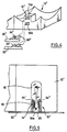
- Each reflector of block 10 has a socket 12 'arranged in the region of the middle of one of its edges, so that the sockets are regularly spaced, at the pitch of the reflectors, along one of the two large edges of said block .
- Each socket 12 ' is constituted by a substantially parallelepipedic cavity 14' open on the center of the reflector.
- Two passages 15a and 15b extend in parallel in a wall separating said cavity from the outside of the block.
- Two flat conductor bars 20 ′, 22 ′ comprise, regularly spaced apart from the sockets 12 ′, electrical and mechanical connection assemblies.
- Each of these assemblies comprises two substantially parallel contact and fixing tabs 24 ′ and 24 ", the first ends of which are fixed on either side of a lug 25 which is integral with the bar and which extends perpendicular to this the latter in order to be able to enter the associated passage 15a or 15b
- the free ends of the two tongues are curved so as to move away from one another as shown.
- the length of the tongues 24 ′ and 24 ′′ is chosen so that their free ends cooperate in abutment with the edges of the upper edge of the cavity 14 ′, while maintaining a state of bending inside said cavity, as illustrated in FIG. 5. In this way, it provides on the one hand the fixing in place by snap-fastening of the associated conductive bar, and on the other hand a retention function of the base 18 of the lamp 16 when the latter is put in place, because the elastic deformation then imprinted on the tongues causes a return force on their part which contributes to tightening the base.
- the fingers 26 provided in the embodiment of Figure 1 become superfluous, and have been omitted.
- the two bars 20 ′ and 22 ′ are here kept suitably spaced from one another thanks to the fact that their respective tongues are inserted in two separate passages 15a and 15b of the sockets 12.
- the conductive bars as described fulfill the following functions: they define, by means of the tabs 24 'and 24 ", the contact surfaces for the electrodes of the lamps; they ensure the electrical connection in lamps parallel to each other and with a power source, and they remain fixed spontaneously in position after their installation by the action of the tabs 24 'and 24 "in the cavities 14 of the sockets.
- the fact of installing the lamps in their sockets causes the assembly to be locked in the assembled position, owing to the fact that the contact and fixing tabs can no longer be released from their cavity 14.
- the insensitivity of the assembly to vibrations is thus notably increased.
- busbars are identical to each other (with the exception of the connection pads), with a reversal of 180 ° . Thus, only one tool may be provided for the manufacture of the two bars.
- the globe or glass for closing the fire has not been shown in the figures. It is clear that the latter can be arranged in close proximity to the lamps and reflectors, without risk of excessive heating, because the light flux produced is significantly more distributed than with single filament lights. The depth of the fire obtained will therefore advantageously be small, with the inherent advantages as indicated above. It is of course possible to provide this closing glass with any means of scattering and / or dispersion of light by diffraction, such as streaks or balls.
- each conductive bar and the associated tongues inserted in the bases of the lamps, and possibly the fingers cooperating with the reflectors can be produced in one piece by simple steps of cutting (for example by stamping) and folding. a metal sheet of appropriate thickness.
- the tongues can be obtained by bending at 90 ° lateral appendages formed in appropriate locations of each of the bars.
Landscapes
- Engineering & Computer Science (AREA)
- Mechanical Engineering (AREA)
- Fastening Of Light Sources Or Lamp Holders (AREA)
- Non-Portable Lighting Devices Or Systems Thereof (AREA)
Claims (8)
Applications Claiming Priority (2)
| Application Number | Priority Date | Filing Date | Title |
|---|---|---|---|
| FR8519156 | 1985-12-24 | ||
| FR8519156A FR2591969B1 (fr) | 1985-12-24 | 1985-12-24 | Feu de signalisation a plusieurs lampes pour vehicule automobile |
Publications (2)
| Publication Number | Publication Date |
|---|---|
| EP0230833A1 EP0230833A1 (de) | 1987-08-05 |
| EP0230833B1 true EP0230833B1 (de) | 1990-02-07 |
Family
ID=9326148
Family Applications (1)
| Application Number | Title | Priority Date | Filing Date |
|---|---|---|---|
| EP19860402900 Expired - Lifetime EP0230833B1 (de) | 1985-12-24 | 1986-12-22 | Leuchte für Fahrzeuge mit mehreren Signallampen |
Country Status (4)
| Country | Link |
|---|---|
| EP (1) | EP0230833B1 (de) |
| DE (1) | DE3668849D1 (de) |
| ES (1) | ES2012767B3 (de) |
| FR (1) | FR2591969B1 (de) |
Families Citing this family (7)
| Publication number | Priority date | Publication date | Assignee | Title |
|---|---|---|---|---|
| JPH079351Y2 (ja) * | 1989-06-20 | 1995-03-06 | スタンレー電気株式会社 | Spg基板用のウェッジベースソケット |
| DE4305584A1 (de) * | 1993-02-24 | 1994-08-25 | Hella Kg Hueck & Co | Fahrzeugleuchte |
| FR2716652B1 (fr) * | 1994-02-28 | 1996-05-10 | Valeo Vision | Feu de signalisation à plusieurs lampes pour véhicule automobile. |
| FR2717957B1 (fr) * | 1994-03-24 | 1996-06-28 | Jaeger | Système de connexion électrique de lampe, à l'aide d'un circuit imprimé souple. |
| FR2718891B1 (fr) * | 1994-04-14 | 1996-07-12 | Valeo Vision | Circuit électrique à bandes découpées, notamment pour un ensemble de feux de signalisation d'un véhicule automobile, comportant des éléments de connexion mâles perfectionnés. |
| FR2739726B1 (fr) * | 1995-10-09 | 1997-12-26 | Valeo Vision | Circuit electrique a au moins une bande decoupee, notamment pour un ensemble de feux de signalisation d'un vehicule automobile, comportant au moins un element de connexion male realise par pliage |
| DE19803399A1 (de) * | 1998-01-29 | 1999-08-05 | Volkswagen Ag | Beleuchtungseinrichtung für Kraftfahrzeuge |
Family Cites Families (4)
| Publication number | Priority date | Publication date | Assignee | Title |
|---|---|---|---|---|
| ES196468Y (es) * | 1971-01-14 | 1975-08-01 | Fiat, S. P. A. | Portalamparas multiple con conectores de alimentacion para linternas de automoviles. |
| US4271408A (en) | 1978-10-17 | 1981-06-02 | Stanley Electric Co., Ltd. | Colored-light emitting display |
| FR2476002A1 (fr) * | 1980-02-20 | 1981-08-21 | Rouquie Jean | Complexe d'eclairage rationnel sur route et de signalisation de securite en ville pour tous vehicules automobiles motocycles et cycles |
| DE3148843C2 (de) | 1981-12-10 | 1986-01-02 | Telefunken electronic GmbH, 7100 Heilbronn | Mehrfach-Leuchtdiodenanordnung |
-
1985
- 1985-12-24 FR FR8519156A patent/FR2591969B1/fr not_active Expired
-
1986
- 1986-12-22 DE DE8686402900T patent/DE3668849D1/de not_active Expired - Lifetime
- 1986-12-22 ES ES86402900T patent/ES2012767B3/es not_active Expired - Lifetime
- 1986-12-22 EP EP19860402900 patent/EP0230833B1/de not_active Expired - Lifetime
Also Published As
| Publication number | Publication date |
|---|---|
| FR2591969A1 (fr) | 1987-06-26 |
| ES2012767B3 (es) | 1990-04-16 |
| EP0230833A1 (de) | 1987-08-05 |
| DE3668849D1 (de) | 1990-03-15 |
| FR2591969B1 (fr) | 1988-04-08 |
Similar Documents
| Publication | Publication Date | Title |
|---|---|---|
| EP0183587B1 (de) | Mehrkontaktverbinderelement mit Mitteln zur Festlegung eines isolierenden Blocks im Gehäuse eines solchen Verbinderelements | |
| FR2922167A1 (fr) | Module d'eclairage pour un phare ou eclairage d'un vehicule automobile. | |
| EP0230833B1 (de) | Leuchte für Fahrzeuge mit mehreren Signallampen | |
| EP2859631A1 (de) | Abdeckplatte mit einem mittel zur zentrierung auf einer inneren komponente einer elektrischen vorrichtung | |
| FR2859954A1 (fr) | Dispositif d'eclairage pour allume-cigare ou prise electrique multi-fonction | |
| EP0375654B1 (de) | Zusammenbau einer Stecklampenfassung und einer Lichtleiste | |
| EP1633024B1 (de) | Steckfassung für eine Keilbasislampe mit Zentrierring | |
| EP1533563B1 (de) | Vorrichtung und Verfahren zur Befestigung einer Lichtquelle an einem Teil eines Kfz-Scheinwerfers | |
| EP0669223B1 (de) | Signalleuchte mit mehreren Lampen für Fahrzeuge | |
| FR2458743A1 (fr) | Appareil d'eclairage de vehicule comportant plusieurs lampes a incandescence | |
| EP0565419A1 (de) | Fahrzeugbeleuchtung mit Leuchtröhre | |
| EP3388735A1 (de) | Leuchtvorrichtung mit elektrischem kontakt zwischen der scheibe und dem gehäuse | |
| FR3052849A1 (fr) | Ampoule pour lampe de vehicule automobile | |
| EP1455134A1 (de) | Befestigungsvorrichtung für eine Lampe | |
| EP0975057A1 (de) | Kontaktteil für Verbindungsbuchse und Verbinder mit einem solchen Kontaktteil | |
| WO2011131894A1 (fr) | Douille a double verrouillage pour ampoule electrique | |
| FR2509840A1 (fr) | Luminaire comportant plusieurs lampes, pour vehicule automobile | |
| EP0660461A1 (de) | Mehrfacher Sockel für Steckdose | |
| FR2600022A1 (fr) | Bloc optique pour vehicule | |
| FR2806249A1 (fr) | Montage des circuits decoupes sur des supports de lampes | |
| EP2408069A1 (de) | Leuchtmittelhalterung zur Montage eines Leuchtmittels | |
| EP0844696B1 (de) | Verbindungsanordnung mit Stecker- und Buchsenteil | |
| EP0677900B1 (de) | Elektrischer Stromkreis aus abgeschnittenen Streifen, insbesondere für einen Zusammenbau von Warnleuchten eines Kraftfahrzeugs welcher verbesserte männliche Verbindungselemente aufweist | |
| EP1022806A1 (de) | Vorrichtung zur Stromversorgung für Fahrzeugleuchte | |
| EP0230197A1 (de) | Linke und rechte Leuchte für Fahrzeuge und deren Herstellungsverfahren |
Legal Events
| Date | Code | Title | Description |
|---|---|---|---|
| PUAI | Public reference made under article 153(3) epc to a published international application that has entered the european phase |
Free format text: ORIGINAL CODE: 0009012 |
|
| AK | Designated contracting states |
Kind code of ref document: A1 Designated state(s): DE ES |
|
| 17P | Request for examination filed |
Effective date: 19871116 |
|
| 17Q | First examination report despatched |
Effective date: 19890623 |
|
| GRAA | (expected) grant |
Free format text: ORIGINAL CODE: 0009210 |
|
| RAP1 | Party data changed (applicant data changed or rights of an application transferred) |
Owner name: VALEO VISION |
|
| AK | Designated contracting states |
Kind code of ref document: B1 Designated state(s): DE ES |
|
| REF | Corresponds to: |
Ref document number: 3668849 Country of ref document: DE Date of ref document: 19900315 |
|
| PLBE | No opposition filed within time limit |
Free format text: ORIGINAL CODE: 0009261 |
|
| STAA | Information on the status of an ep patent application or granted ep patent |
Free format text: STATUS: NO OPPOSITION FILED WITHIN TIME LIMIT |
|
| 26N | No opposition filed | ||
| PGFP | Annual fee paid to national office [announced via postgrant information from national office to epo] |
Ref country code: ES Payment date: 19991209 Year of fee payment: 14 |
|
| PGFP | Annual fee paid to national office [announced via postgrant information from national office to epo] |
Ref country code: DE Payment date: 19991218 Year of fee payment: 14 |
|
| PG25 | Lapsed in a contracting state [announced via postgrant information from national office to epo] |
Ref country code: DE Free format text: LAPSE BECAUSE OF NON-PAYMENT OF DUE FEES Effective date: 20011002 |
|
| PG25 | Lapsed in a contracting state [announced via postgrant information from national office to epo] |
Ref country code: ES Free format text: LAPSE BECAUSE OF NON-PAYMENT OF DUE FEES Effective date: 20011223 |
|
| REG | Reference to a national code |
Ref country code: ES Ref legal event code: FD2A Effective date: 20020112 |
|
| REG | Reference to a national code |
Ref country code: HK Ref legal event code: AM43 Ref document number: 1150423 Country of ref document: HK |