EP0230765B1 - Block pattern tyre - Google Patents
Block pattern tyre Download PDFInfo
- Publication number
- EP0230765B1 EP0230765B1 EP19860309944 EP86309944A EP0230765B1 EP 0230765 B1 EP0230765 B1 EP 0230765B1 EP 19860309944 EP19860309944 EP 19860309944 EP 86309944 A EP86309944 A EP 86309944A EP 0230765 B1 EP0230765 B1 EP 0230765B1
- Authority
- EP
- European Patent Office
- Prior art keywords
- groove
- tyre
- lateral
- grooves
- tread
- Prior art date
- Legal status (The legal status is an assumption and is not a legal conclusion. Google has not performed a legal analysis and makes no representation as to the accuracy of the status listed.)
- Expired - Lifetime
Links
Images


Classifications
-
- B—PERFORMING OPERATIONS; TRANSPORTING
- B60—VEHICLES IN GENERAL
- B60C—VEHICLE TYRES; TYRE INFLATION; TYRE CHANGING; CONNECTING VALVES TO INFLATABLE ELASTIC BODIES IN GENERAL; DEVICES OR ARRANGEMENTS RELATED TO TYRES
- B60C11/00—Tyre tread bands; Tread patterns; Anti-skid inserts
- B60C11/03—Tread patterns
- B60C11/13—Tread patterns characterised by the groove cross-section, e.g. for buttressing or preventing stone-trapping
- B60C11/1369—Tie bars for linking block elements and bridging the groove
-
- B—PERFORMING OPERATIONS; TRANSPORTING
- B60—VEHICLES IN GENERAL
- B60C—VEHICLE TYRES; TYRE INFLATION; TYRE CHANGING; CONNECTING VALVES TO INFLATABLE ELASTIC BODIES IN GENERAL; DEVICES OR ARRANGEMENTS RELATED TO TYRES
- B60C11/00—Tyre tread bands; Tread patterns; Anti-skid inserts
- B60C11/03—Tread patterns
- B60C11/11—Tread patterns in which the raised area of the pattern consists only of isolated elements, e.g. blocks
-
- B—PERFORMING OPERATIONS; TRANSPORTING
- B60—VEHICLES IN GENERAL
- B60C—VEHICLE TYRES; TYRE INFLATION; TYRE CHANGING; CONNECTING VALVES TO INFLATABLE ELASTIC BODIES IN GENERAL; DEVICES OR ARRANGEMENTS RELATED TO TYRES
- B60C11/00—Tyre tread bands; Tread patterns; Anti-skid inserts
- B60C11/03—Tread patterns
- B60C11/12—Tread patterns characterised by the use of narrow slits or incisions, e.g. sipes
-
- B—PERFORMING OPERATIONS; TRANSPORTING
- B60—VEHICLES IN GENERAL
- B60C—VEHICLE TYRES; TYRE INFLATION; TYRE CHANGING; CONNECTING VALVES TO INFLATABLE ELASTIC BODIES IN GENERAL; DEVICES OR ARRANGEMENTS RELATED TO TYRES
- B60C11/00—Tyre tread bands; Tread patterns; Anti-skid inserts
- B60C11/03—Tread patterns
- B60C11/13—Tread patterns characterised by the groove cross-section, e.g. for buttressing or preventing stone-trapping
Definitions
- This invention relates to a block pattern tyre and in particular to an all-weather steel radial tyre for truck and bus.
- tyres particularly steel radial tyres for truck and bus are required to have good on-the-snow performance, wet grip performance, resistance to uneven wear, and long life.
- tyres are usually provided with a tread pattern which turns from a block pattern when the tyre is new into a rib pattern formed by the blocks being connected to one another after the intermediate stage of wear.
- a tread pattern is shown in Fig.4 and 5 and comprises two circumferential grooves 1 and 2, blocks 3 and 4 formed between the circumferential grooves 1 and 2; and lateral grooves 5 formed between the blocks 3 and 4.
- the blocks 3 each have a low rib part 8 having a depth about one half that of the main groove depth in the middle portion of the lateral groove 5.
- the tyre functions as a block pattern tyre which has separate blocks 3 and when the tyre has worn by more than its tread depth low rib parts 8 become flush with the tread surface and the blocks 3 are connected with each other. Accordingly, the tyre then becomes substantially a rib pattern tyre.
- Such a tyre has a longer life than an ordinary block pattern tyre because uneven wear among the blocks is prevented by the low rib parts 8 in the lateral grooves 5 which increase the stiffness of the blocks in the circumferential direction.
- these tyres are poor in on-the-snow performance and rapidly also turn poor in wet grip performance when worn by more than half of tread depth because of the low rib parts 8.
- a tyre according to the preamble of claim 1 is known, eg. from GB-A-2008043.
- the invention provides a block pattern tyre having a tread provided with circumferential grooves, lateral grooves extending between the circumferential grooves to form tread blocks and a narrow groove disposed in each lateral groove wherein each narrow groove has a substantially constant depth similar to the depth of the circumferential groves and each narrow groove extends between the circumferential grooves and across a protruding portion of the groove bottom through the lateral grooves and each narrow groove has a width such that the narrow groove closes in the ground contacting patch in use of the vehicle characterised in that said protruding portion is a middle portion and the lateral groove decreases in depth towards said middle portion of the lateral groove from each circumferential groove such that the lateral groove in said middle portion has no depth such that its bottom is flush with the tread surface of the tread blocks.
- the block pattern tyre is for a 10.00R20 tyre and comprises four straight circumferential grooves 1 and 2 which divide the tread into five ribs; a centre rib along the tyre equator 7, a pair of shoulder ribs and a pair of middle ribs between the centre rib and shoulder rib.
- the circumferential groove 1 has a zig-zag groove bottom which is narrower than the groove width at the top to provide steps in the sidewalls of the circumferential groove 1.
- Lateral grooves 5 extend between the circumferential grooves 1 and 2 to divide each middle rib into a plurality of blocks 3, and in addition other lateral grooves extend across the centre rib and shoulder ribs to divide them into a plurality of blocks 4.
- each lateral groove 5 decreases towards the middle portion thereof from each circumferential groove 1 and 2 so that the bottom of the lateral groove 5 is flush with the tread surface of the blocks 3 in the middle portion of the lateral groove 5.
- the lateral grooves 5 comprise two grooves 5a and 5b interrupted by a protrusion 6 in the middle of each lateral groove 5.
- Each end of the lateral grooves 5a and 5b is connected to the circumferential groove 1 or 2, respectively.
- a narrow slit or groove 10 extends between the adjacent circumferential grooves 1 and 2 across the protrusion 6 through the grooves 5a and 5b.
- the depth of the narrow groove 10 is the same as the circumferential grooves.
- the width of the narrow grooves 10 is about 0.7 mm so that the narrow grooves close completely when the tread contacts the ground.
- the tread thus substantially turns from a block pattern into a rib pattern as it wears, but with the addition of the narrow grooves.
- the tyre has the original on-the-snow performance of the block pattern tyre when new, but owing to the narrow grooves, the tyre still has good wet grip performance when it is used as worn.
- the tyre does not suffer from uneven wear although it is effectively a block pattern tyre.
- the narrow grooves (10) may be of any width which ensures that the grooves close in the contact patch and a width of 1 mm of less is prefered.
- This narrow width provides complete groove closure which provides low stiffness of the blocks throughout the life of the tyre and thus gives good on snow grip, the narrow grooves also provide effective drainage even when part worn but cause no uneven wear because when closed the tyre pattern acts as a rib type of tread.
- the middle portion of the lateral grooves is flush with the unworn tread surface of the tread blocks.
- the narrow groove has a width of not more than 1 mm to ensure complete closure in the contact patch and a prefered groove width is 0.7 mm.
Description
- This invention relates to a block pattern tyre and in particular to an all-weather steel radial tyre for truck and bus.
- Usually, all-weather tyres, particularly steel radial tyres for truck and bus are required to have good on-the-snow performance, wet grip performance, resistance to uneven wear, and long life. For good on-the-snow performance and long life, such tyres are usually provided with a tread pattern which turns from a block pattern when the tyre is new into a rib pattern formed by the blocks being connected to one another after the intermediate stage of wear. Such a conventional tread pattern is shown in Fig.4 and 5 and comprises two
circumferential grooves 1 and 2,blocks circumferential grooves 1 and 2; andlateral grooves 5 formed between theblocks blocks 3 each have alow rib part 8 having a depth about one half that of the main groove depth in the middle portion of thelateral groove 5. Thus, when this conventional tyre is new, the tyre functions as a block pattern tyre which hasseparate blocks 3 and when the tyre has worn by more than its tread depthlow rib parts 8 become flush with the tread surface and theblocks 3 are connected with each other. Accordingly, the tyre then becomes substantially a rib pattern tyre. - Such a tyre has a longer life than an ordinary block pattern tyre because uneven wear among the blocks is prevented by the
low rib parts 8 in thelateral grooves 5 which increase the stiffness of the blocks in the circumferential direction. However, these tyres are poor in on-the-snow performance and rapidly also turn poor in wet grip performance when worn by more than half of tread depth because of thelow rib parts 8. - A tyre according to the preamble of claim 1 is known, eg. from GB-A-2008043.
- It is an object of the present invention to provide a block pattern tyre tread which turns into a rib pattern without sacrificing on the snow performance or wet grip performance.
- Accordingly the invention provides a block pattern tyre having a tread provided with circumferential grooves, lateral grooves extending between the circumferential grooves to form tread blocks and a narrow groove disposed in each lateral groove wherein each narrow groove has a substantially constant depth similar to the depth of the circumferential groves and each narrow groove extends between the circumferential grooves and across a protruding portion of the groove bottom through the lateral grooves and each narrow groove has a width such that the narrow groove closes in the ground contacting patch in use of the vehicle characterised in that said protruding portion is a middle portion and the lateral groove decreases in depth towards said middle portion of the lateral groove from each circumferential groove such that the lateral groove in said middle portion has no depth such that its bottom is flush with the tread surface of the tread blocks.
- The present invention will be apparent from the following example, by way of example only, in conjunction with the attached drawings in which:
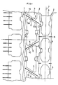
- Fig. 1. is a partial developed view of the tread pattern of one embodiment of this invention.
- Fig. 2. is a sectional view taken along the line B-B in Fig. 1.
- Fig. 3. is a sectional view taken along the line C-C in Fig. 1.
- Fig. 4. is a partial developed view of the tread pattern of a conventional tyre and
- Fig. 5. is a sectional view taken along the line D-D in Fig. 4.
- In Figs. 1 to 3, the block pattern tyre is for a 10.00R20 tyre and comprises four straight
circumferential grooves 1 and 2 which divide the tread into five ribs; a centre rib along the tyre equator 7, a pair of shoulder ribs and a pair of middle ribs between the centre rib and shoulder rib. - The circumferential groove 1 has a zig-zag groove bottom which is narrower than the groove width at the top to provide steps in the sidewalls of the circumferential groove 1.
-
Lateral grooves 5 extend between thecircumferential grooves 1 and 2 to divide each middle rib into a plurality ofblocks 3, and in addition other lateral grooves extend across the centre rib and shoulder ribs to divide them into a plurality ofblocks 4. - The depth of each
lateral groove 5 decreases towards the middle portion thereof from eachcircumferential groove 1 and 2 so that the bottom of thelateral groove 5 is flush with the tread surface of theblocks 3 in the middle portion of thelateral groove 5. Thus thelateral grooves 5 comprise twogrooves protrusion 6 in the middle of eachlateral groove 5. Each end of thelateral grooves circumferential groove 1 or 2, respectively. - A narrow slit or
groove 10 extends between the adjacentcircumferential grooves 1 and 2 across theprotrusion 6 through thegrooves - The depth of the
narrow groove 10 is the same as the circumferential grooves. The width of thenarrow grooves 10 is about 0.7 mm so that the narrow grooves close completely when the tread contacts the ground. In use of the tyre the tread thus substantially turns from a block pattern into a rib pattern as it wears, but with the addition of the narrow grooves. The tyre has the original on-the-snow performance of the block pattern tyre when new, but owing to the narrow grooves, the tyre still has good wet grip performance when it is used as worn. In addition, the tyre does not suffer from uneven wear although it is effectively a block pattern tyre. - The narrow grooves (10) may be of any width which ensures that the grooves close in the contact patch and a width of 1 mm of less is prefered. This narrow width provides complete groove closure which provides low stiffness of the blocks throughout the life of the tyre and thus gives good on snow grip, the narrow grooves also provide effective drainage even when part worn but cause no uneven wear because when closed the tyre pattern acts as a rib type of tread.
- The middle portion of the lateral grooves is flush with the unworn tread surface of the tread blocks.
- The narrow groove has a width of not more than 1 mm to ensure complete closure in the contact patch and a prefered groove width is 0.7 mm.
Claims (2)
Applications Claiming Priority (2)
| Application Number | Priority Date | Filing Date | Title |
|---|---|---|---|
| JP2986/86 | 1985-12-27 | ||
| JP60298686A JPS62155105A (en) | 1985-12-27 | 1985-12-27 | Block pattern tire |
Publications (2)
| Publication Number | Publication Date |
|---|---|
| EP0230765A1 EP0230765A1 (en) | 1987-08-05 |
| EP0230765B1 true EP0230765B1 (en) | 1991-03-20 |
Family
ID=17862967
Family Applications (1)
| Application Number | Title | Priority Date | Filing Date |
|---|---|---|---|
| EP19860309944 Expired - Lifetime EP0230765B1 (en) | 1985-12-27 | 1986-12-19 | Block pattern tyre |
Country Status (5)
| Country | Link |
|---|---|
| EP (1) | EP0230765B1 (en) |
| JP (1) | JPS62155105A (en) |
| AU (1) | AU591744B2 (en) |
| CA (1) | CA1296981C (en) |
| DE (1) | DE3678273D1 (en) |
Families Citing this family (7)
| Publication number | Priority date | Publication date | Assignee | Title |
|---|---|---|---|---|
| WO1997046400A1 (en) * | 1996-06-07 | 1997-12-11 | The Goodyear Tire & Rubber Company | A convertible tread for a radial truck or trailer tire |
| US6481480B1 (en) | 1996-06-07 | 2002-11-19 | The Goodyear Tire & Rubber Company | Convertible tread for a radial truck or trailer tire |
| IT1289182B1 (en) | 1997-01-20 | 1998-09-29 | Pirelli | TIRE WITH LOW ROLLING RESISTANCE IN PARTICULAR FOR DRIVE WHEELS OF HEAVY VEHICLES |
| DE102011001295A1 (en) * | 2011-03-15 | 2012-09-20 | Continental Reifen Deutschland Gmbh | Vehicle tires |
| JP6110070B2 (en) * | 2012-01-20 | 2017-04-05 | 株式会社ブリヂストン | tire |
| JP5806707B2 (en) * | 2013-07-03 | 2015-11-10 | 住友ゴム工業株式会社 | Pneumatic tire |
| JP2022099486A (en) * | 2020-12-23 | 2022-07-05 | Toyo Tire株式会社 | Pneumatic tire |
Family Cites Families (9)
| Publication number | Priority date | Publication date | Assignee | Title |
|---|---|---|---|---|
| DE1605638A1 (en) * | 1967-11-02 | 1970-01-29 | Continental Gummi Werke Ag | Tread profiling for pneumatic motor vehicle tires |
| DE6941584U (en) * | 1969-10-09 | 1970-02-12 | Continental Gummi Werke Ag | VEHICLE AIR TIRES |
| FR2076641A5 (en) * | 1970-01-21 | 1971-10-15 | Michelin & Cie | |
| JPS5438005A (en) * | 1977-09-01 | 1979-03-22 | Bridgestone Corp | Pneumatic tire for heavy vehicle |
| JPS5470503A (en) * | 1977-11-17 | 1979-06-06 | Bridgestone Corp | Air-inflated tire for heavy load |
| US4296789A (en) * | 1978-02-14 | 1981-10-27 | The Goodyear Tire & Rubber Company | Tread for pneumatic tire |
| DE8137115U1 (en) * | 1981-12-19 | 1982-07-22 | Continental Gummi-Werke Ag, 3000 Hannover | MOTOR VEHICLE TIRES, ESPECIALLY RESERVE TIRES |
| JPS58199204A (en) * | 1982-05-12 | 1983-11-19 | Bridgestone Corp | Pneumatic radial tyre for heavy load |
| GB2142885B (en) * | 1983-07-07 | 1987-05-28 | Dunlop Ltd | Tyre tread |
-
1985
- 1985-12-27 JP JP60298686A patent/JPS62155105A/en active Pending
-
1986
- 1986-12-17 AU AU66651/86A patent/AU591744B2/en not_active Ceased
- 1986-12-19 DE DE8686309944T patent/DE3678273D1/en not_active Expired - Fee Related
- 1986-12-19 EP EP19860309944 patent/EP0230765B1/en not_active Expired - Lifetime
- 1986-12-23 CA CA000526153A patent/CA1296981C/en not_active Expired - Fee Related
Also Published As
| Publication number | Publication date |
|---|---|
| JPS62155105A (en) | 1987-07-10 |
| AU6665186A (en) | 1987-07-02 |
| EP0230765A1 (en) | 1987-08-05 |
| DE3678273D1 (en) | 1991-04-25 |
| AU591744B2 (en) | 1989-12-14 |
| CA1296981C (en) | 1992-03-10 |
Similar Documents
| Publication | Publication Date | Title |
|---|---|---|
| US6116309A (en) | Tread for a tire including five rib parts | |
| US6142200A (en) | Truck steer tire tread including circumferential grooves | |
| US5361815A (en) | Tread for a tire with blocks and ribs | |
| CA1276865C (en) | Pneumatic tires having excellent traction and braking performances | |
| US5022448A (en) | Pneumatic tire including lateral tread grooves with a bridge thereacross | |
| US4683928A (en) | Pneumatic tire tread with a central zone and lateral zones of different hardness | |
| EP0178859B1 (en) | Pneumatic radial tyre for heavy load vehicles | |
| EP0062970B1 (en) | Tyre for a two wheeled single-track vehicle | |
| CA1302854C (en) | Pneumatic radial tire | |
| CA1284935C (en) | All-terrain pneumatic tire | |
| US20030047262A1 (en) | Asymmetrical vehicle tire with balanced wet and dry performance | |
| US4977942A (en) | Pneumatic tire having defined lug groove configuration | |
| US4278121A (en) | All-season pneumatic tire tread | |
| US20220371375A1 (en) | Tire | |
| EP0230765B1 (en) | Block pattern tyre | |
| JPH05278414A (en) | Pneumatic tire | |
| JPH09188110A (en) | Pneumatic radial tire for heavy load | |
| JPH0326964Y2 (en) | ||
| JPH07172107A (en) | Pneumatic radial tire | |
| EP0485884B1 (en) | Sipes for tire treads | |
| JP3101555B2 (en) | Pneumatic tire | |
| EP0638446B1 (en) | Tread for pneumatic vehicle tyres | |
| NZ214120A (en) | Radial tyre tread: three circumferential wide grooves, two intermediate narrow grooves and transversely interconnecting sipes | |
| JP2659705B2 (en) | Pneumatic tire with excellent traction and braking performance | |
| EP0370747B1 (en) | Pneumatic tyre |
Legal Events
| Date | Code | Title | Description |
|---|---|---|---|
| PUAI | Public reference made under article 153(3) epc to a published international application that has entered the european phase |
Free format text: ORIGINAL CODE: 0009012 |
|
| AK | Designated contracting states |
Kind code of ref document: A1 Designated state(s): DE FR GB |
|
| 17P | Request for examination filed |
Effective date: 19880123 |
|
| 17Q | First examination report despatched |
Effective date: 19891016 |
|
| GRAA | (expected) grant |
Free format text: ORIGINAL CODE: 0009210 |
|
| AK | Designated contracting states |
Kind code of ref document: B1 Designated state(s): DE FR GB |
|
| ET | Fr: translation filed | ||
| REF | Corresponds to: |
Ref document number: 3678273 Country of ref document: DE Date of ref document: 19910425 |
|
| PLBE | No opposition filed within time limit |
Free format text: ORIGINAL CODE: 0009261 |
|
| STAA | Information on the status of an ep patent application or granted ep patent |
Free format text: STATUS: NO OPPOSITION FILED WITHIN TIME LIMIT |
|
| 26N | No opposition filed | ||
| PGFP | Annual fee paid to national office [announced via postgrant information from national office to epo] |
Ref country code: FR Payment date: 19971209 Year of fee payment: 12 |
|
| PGFP | Annual fee paid to national office [announced via postgrant information from national office to epo] |
Ref country code: GB Payment date: 19971210 Year of fee payment: 12 |
|
| PGFP | Annual fee paid to national office [announced via postgrant information from national office to epo] |
Ref country code: DE Payment date: 19971230 Year of fee payment: 12 |
|
| PG25 | Lapsed in a contracting state [announced via postgrant information from national office to epo] |
Ref country code: GB Free format text: LAPSE BECAUSE OF NON-PAYMENT OF DUE FEES Effective date: 19981219 |
|
| GBPC | Gb: european patent ceased through non-payment of renewal fee |
Effective date: 19981219 |
|
| PG25 | Lapsed in a contracting state [announced via postgrant information from national office to epo] |
Ref country code: FR Free format text: LAPSE BECAUSE OF NON-PAYMENT OF DUE FEES Effective date: 19990831 |
|
| REG | Reference to a national code |
Ref country code: FR Ref legal event code: ST |
|
| PG25 | Lapsed in a contracting state [announced via postgrant information from national office to epo] |
Ref country code: DE Free format text: LAPSE BECAUSE OF NON-PAYMENT OF DUE FEES Effective date: 19991001 |