EP0230640A2 - Mittels eines Gases eingetriebener Anker und dessen Zuwasserlassungsvorrichtung - Google Patents
Mittels eines Gases eingetriebener Anker und dessen Zuwasserlassungsvorrichtung Download PDFInfo
- Publication number
- EP0230640A2 EP0230640A2 EP86117887A EP86117887A EP0230640A2 EP 0230640 A2 EP0230640 A2 EP 0230640A2 EP 86117887 A EP86117887 A EP 86117887A EP 86117887 A EP86117887 A EP 86117887A EP 0230640 A2 EP0230640 A2 EP 0230640A2
- Authority
- EP
- European Patent Office
- Prior art keywords
- anchor
- vessel
- launching
- pressure vessel
- launcher
- Prior art date
- Legal status (The legal status is an assumption and is not a legal conclusion. Google has not performed a legal analysis and makes no representation as to the accuracy of the status listed.)
- Granted
Links
Images

Classifications
-
- B—PERFORMING OPERATIONS; TRANSPORTING
- B63—SHIPS OR OTHER WATERBORNE VESSELS; RELATED EQUIPMENT
- B63B—SHIPS OR OTHER WATERBORNE VESSELS; EQUIPMENT FOR SHIPPING
- B63B21/00—Tying-up; Shifting, towing, or pushing equipment; Anchoring
- B63B21/24—Anchors
- B63B21/26—Anchors securing to bed
- B63B21/28—Anchors securing to bed driven in by explosive charge
Definitions
- U.S. Patent Nos. 3,118,417 and 3,371,643 are examples of this type of structure for setting a subsea anchor.
- U.S. Patent No. 3.646,598 discloses an air type of pile driver.
- Other types of anchor burying structures utilizing air jets are disclosed in U.S. Patent Nos. 4,347,802 and 4,076,313.
- the present invention relates to an improved subsea anchor and anchor setting system which is portable and easily and quickly set.
- the complete system includes an anchor projectile section having an anchor body, beams pivotally connected at their lower end to the body and interconnected by flexible segments or other suitable anchoring means, a pressure storage or launching section having a launching tube in which the upper body of the projectile section is positioned for being launched therefrom, a drag plate secured around the launching section with substantial weight therein to resist upward movement of the launching section when the anchor projectile section is released for launching into the sea bottom, means for releasably securing the anchor projectile section within the launching section until the anchor is to be launched for setting in the bottom.
- An object of the present invention is to provide an improved subsea anchor and anchor setting system which is portable and may be set quickly without the danger of handling explosives.
- Another object is to provide an improved portable subsea anchor which is simple and quick to set
- a further object is to provide an improved portable subsea anchor having low drag during setting and high drag when loaded after setting.
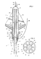
- FIGURES 1 and 2 The improved anchor A of the present invention with the launching system structure L is shown in details in FIGURES 1 and 2 and its support from vessel V and the manner of positioning the complete structure for anchoring is disclosed in FIGURES 5 through 8. Some additional details of anchor A are shown in FIGURES 3 and 4.
- Anchor A includes body 10 having upper rod 12, lower rod 14 with flange 16 therebetween.
- Lower rod 14 includes slot 18 near its upper end in which pulley 20 is positioned for the reasons hereinafter set forth.
- Cone 22 is positioned on the lower end of lower rod 14.
- Rod 14 immediately above cone 22 is of a reduced diameter as shown at 24 which extends upwardly to a point a short distance below slot 18.
- Shoulder 26 formed above cone 22 faces upwardly and beams 28 are pivotally mounted thereto by suitable pivoting means 29 such as pins and brackets so that in their retracted position as shown in FIGURE 1 they have a diameter smaller than the outer diameter of shoulder 26 or they are within the shadow of cone 22.
- Launching system L includes pressure vessel 38 with tube 36 supported within vessel 38 by braces 40.
- the upper end of tube 36 is flared outward as shown at 42 and is spaced from the upper interior of vessel 38.
- the lower end of vessel 38 is surrounded by flange 44 which is secured to flange 46 on the exterior of tube 36 by clamp 48.
- Releasable engaging means 50 connects from launching structure L to anchor A and includes collet connector 52 which includes fingers 54 engaging end flange 56 on tube 36 and flange 16 on anchor body 10.
- Collet connector 52 also includes an actuator (not shown) which causes wedge ring 58 to be moved with respect to fingers 54 in the usual manner.
- a suitable source of hydraulic fluid is supplied to connector 52 through line 60.
- Drag pan 62 is secured around the exterior of pressure vessel 38 and is supported therefrom by gussets 64. As shown, drag pan 62 is slightly conical with the apex of the cone facing downward. The interior of pan 62 is suitable weighted as by filling the upper interior of pan 62 with concrete 66 or other weighting material. Pan 62 has sufficient diameter to create a vertical water mass and hydrodynamic drag.
- Anchor cable 68 connects to messenger cable 70 which is coiled around lower rod 14 immediately above pulley 20.
- Messenger cable 70 extends through slot 18 in engagement with pulley 20 and connects to the lower end of collet connector 52 which is secured to the lower end of pressure vessel 38.
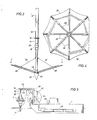
- anchor A and launching system structure L are supported from vessel V by lifting cable 72 which extends to structure L from hoist 74 that is supported on arm 76 mounted on davit 78 on the deck of vessel V.
- Anchor cable 68 extends to drum 80 and hydraulic line 60 and fluid pressurizing line 82 which connects to the upper end of pressure vessel 38 are mounted on drums such as drum 84.
- Vessel also includes compressor 86 which connects to enlongated storage tanks 88 which may be supported on the exterior of vessel V.
- Line 82 connects to tanks 88 through suitable controls for the charging of the interior of pressure vessel 38.
- anchor A and launching structure L With the anchor A and launching structure L positioned as shown in FIGURE 5, they are lowered downward through the water until anchor A is embedded in sea bottom B with launching structure L positioned on the surface of sea bottom B.
- the anchor A preferably is fully into the sea bottom B with launching structure L having its pan near sea bottom B as shown in FIGURE 6. In this position, launching structure L is charged through pressurizing line 82.
- collet connector 52 With launching system fully charged, collet connector 52 is disengaged allowing the charge of fluid pressure within pressure vessel 38 to expand with the movement of anchor rod 12 downwardly through tube 36 to launch anchor A into the sea bottom B. Sufficient pressure is provided in pressure vessel 38 to allow anchor A to be launched into sea bottom B with sufficient force to cause anchor A to move through sea bottom B to a depth which allows the desired anchoring.
- the position of anchor A at the end of its movement through the earth at sea bottom is shown in FIGURE 7.
- messenger cable 70 is connected between the lower end of collet connector 62 to anchor cable 68, the retrieving of launching structure L, as shown in FIGURE 8, brings the collet connector end of messenger cable 70 to the vessel V.
- Messenger cable 70 is pulled from the vessel V causing anchor cable 68 to be pulled through pulley 20 and back to vessel V.
- anchor cable 68 With anchor cable 68 secured on vessel V, it is hoisted to cause anchor A to be set as shown in FIGURE 8.
- the upward movement of anchor A causes beams 28 to pivot outwardly until they are in a position supported by cables 32 and segments 30 are unfolded to provide an inverted umbrella-like structure expanded into the earth of sea bottom B. In this expanded position, anchor A is firmly set and provides the desired anchoring through anchor cable 68.
- the doubling of anchor cable 68 over pulley 20 allows easy replacement of anchor cable 68 whenever it is in need of replacement due to wear or corrosion or other damage.
Landscapes
- Chemical & Material Sciences (AREA)
- Engineering & Computer Science (AREA)
- Combustion & Propulsion (AREA)
- Mechanical Engineering (AREA)
- Ocean & Marine Engineering (AREA)
- Earth Drilling (AREA)
- Adornments (AREA)
- Dowels (AREA)
- Joining Of Building Structures In Genera (AREA)
- Sampling And Sample Adjustment (AREA)
- Conveying And Assembling Of Building Elements In Situ (AREA)
Priority Applications (1)
| Application Number | Priority Date | Filing Date | Title |
|---|---|---|---|
| AT86117887T ATE73402T1 (de) | 1986-01-21 | 1986-12-22 | Mittels eines gases eingetriebener anker und dessen zuwasserlassungsvorrichtung. |
Applications Claiming Priority (2)
| Application Number | Priority Date | Filing Date | Title |
|---|---|---|---|
| US06/820,650 US4682559A (en) | 1986-01-21 | 1986-01-21 | Gas driven anchor and launching system therefor |
| US820650 | 1986-01-21 |
Publications (3)
| Publication Number | Publication Date |
|---|---|
| EP0230640A2 true EP0230640A2 (de) | 1987-08-05 |
| EP0230640A3 EP0230640A3 (en) | 1988-03-09 |
| EP0230640B1 EP0230640B1 (de) | 1992-03-11 |
Family
ID=25231378
Family Applications (1)
| Application Number | Title | Priority Date | Filing Date |
|---|---|---|---|
| EP86117887A Expired EP0230640B1 (de) | 1986-01-21 | 1986-12-22 | Mittels eines Gases eingetriebener Anker und dessen Zuwasserlassungsvorrichtung |
Country Status (5)
| Country | Link |
|---|---|
| US (1) | US4682559A (de) |
| EP (1) | EP0230640B1 (de) |
| JP (1) | JPS62175292A (de) |
| AT (1) | ATE73402T1 (de) |
| DE (1) | DE3684290D1 (de) |
Cited By (2)
| Publication number | Priority date | Publication date | Assignee | Title |
|---|---|---|---|---|
| WO1999046163A1 (en) * | 1998-03-10 | 1999-09-16 | Umoe Anchor Contracting As | Sea bed anchoring |
| GB2340099A (en) * | 1998-07-29 | 2000-02-16 | Philip Head | Mooring systems |
Families Citing this family (20)
| Publication number | Priority date | Publication date | Assignee | Title |
|---|---|---|---|---|
| JPH01141190A (ja) * | 1987-11-27 | 1989-06-02 | Houzan Tekko Kk | 海底アンカーの形成工法および装置 |
| US5363789A (en) * | 1993-09-15 | 1994-11-15 | Single Buoy Moorings Inc. | Disconnectable mooring system |
| BR9603600A (pt) * | 1996-08-30 | 1998-05-19 | Petroleo Brasileiro Sa | Ancora do tipo placa e seu respectivo processo de instalação |
| US6129487A (en) | 1998-07-30 | 2000-10-10 | Bermingham Construction Limited | Underwater pile driving tool |
| US6360495B1 (en) * | 1999-05-17 | 2002-03-26 | The United States Of America As Represented By The Secretary Of The Navy | Sand spike system |
| GB0130447D0 (en) * | 2001-12-20 | 2002-02-06 | Stolt Offshore Ltd | Anchor for vehicle vehicle and anchor in combination and method of using the anchor |
| US6655454B1 (en) | 2002-06-20 | 2003-12-02 | Danny Joe Floyd | Check enhancer for injecting fluids into a well |
| BRPI0405799B1 (pt) * | 2004-12-21 | 2018-06-12 | Petroleo Brasileiro S.A. - Petrobras | Estaca torpedo com poder de garra aumentado e com abas para ancoragem permanente ou temporária de estruturas flutuantes e método de instalação |
| US20080141922A1 (en) * | 2006-12-13 | 2008-06-19 | Edmund Muehlner | Folding torpedo anchor for marine moorings |
| WO2010036413A2 (en) * | 2008-06-02 | 2010-04-01 | Causwave, Inc. | Projectile propulsion system |
| RU2528013C2 (ru) * | 2008-11-03 | 2014-09-10 | Козвейв, Инк. | Генерация электрической энергии |
| US20100290839A1 (en) * | 2009-05-18 | 2010-11-18 | Moshe Meller | Anchoring system for anchoring a base that supports a wind turbine |
| US8378509B2 (en) * | 2009-11-03 | 2013-02-19 | Causwave, Inc. | Multiphase material generator vehicle |
| US20120251244A1 (en) * | 2011-03-31 | 2012-10-04 | Thomas Toedtman | Methods and device to improve the quality of contained hydrocarbon liquids and particularly oil recovered from an undersea oil leak containment chamber. |
| US8607773B1 (en) * | 2012-06-04 | 2013-12-17 | Steven L. Schultz | Pneumatically driven projectile weapon |
| USD691082S1 (en) * | 2012-08-22 | 2013-10-08 | Superior International Industries, Inc. | Anchor |
| US20150021454A1 (en) * | 2013-03-12 | 2015-01-22 | Itzhak Sapir | Autonomous Remote Anchor System |
| CN112982397A (zh) * | 2021-02-05 | 2021-06-18 | 王超 | 一种可回收充气伞撑式气囊锚杆及其使用方法 |
| KR102501321B1 (ko) * | 2021-05-20 | 2023-02-21 | 이현후 | 해상 바닥 설치용 바이브레이션 말뚝 설치장치 |
| CN113581372B (zh) * | 2021-08-13 | 2022-03-18 | 江苏科技大学 | 一种可拆卸高压喷射式动力锚 |
Family Cites Families (19)
| Publication number | Priority date | Publication date | Assignee | Title |
|---|---|---|---|---|
| US3109419A (en) * | 1961-07-14 | 1963-11-05 | Hayward Gilbert Osborne | Harpoon guns |
| US3212110A (en) * | 1961-11-06 | 1965-10-19 | Paul A Lombardo | Collapsible anchor and buoy |
| US3118417A (en) * | 1962-07-30 | 1964-01-21 | Stanwick Tad | Method and apparatus for anchor embedment |
| US3371643A (en) * | 1962-08-06 | 1968-03-05 | Dunham William Howard | Hydraulically actuated driver |
| NL301137A (de) * | 1963-01-10 | |||
| US3315629A (en) * | 1964-11-30 | 1967-04-25 | Phillips Petroleum Co | Underwater anchor gun device |
| US3291092A (en) * | 1964-12-21 | 1966-12-13 | Magnavox Co | Mooring apparatus |
| US3280782A (en) * | 1965-05-24 | 1966-10-25 | North American Aviation Inc | Marine anchor |
| US3311080A (en) * | 1965-09-28 | 1967-03-28 | Victor C Anderson | Pressure actuated anchor |
| US3520268A (en) * | 1967-06-22 | 1970-07-14 | Bernal L Bower | Ballistics embedment anchors |
| US3646598A (en) * | 1969-06-25 | 1972-02-29 | Bolt Associates Inc | Pile driver systems apparatus and method for driving a pile |
| US3777688A (en) * | 1970-06-25 | 1973-12-11 | Us Navy | Method and apparatus for emplacement of long beams in rugged sea bottom areas |
| US3910218A (en) * | 1974-02-04 | 1975-10-07 | Us Navy | Propellant-actuated deep water anchor |
| US4033281A (en) * | 1976-01-07 | 1977-07-05 | Poseidom Marketing And Development Co. | Extra heavy duty hydrostatic anchor together with its extra heavy duty tether cable |
| US4076313A (en) * | 1976-08-20 | 1978-02-28 | Sperandeo Iii Frank P | Underwater recovery apparatus |
| SU667640A1 (ru) * | 1977-01-10 | 1979-06-15 | Войсковая Часть 13073 | Плоский выстреливаемый анкер |
| US4347802A (en) * | 1980-05-19 | 1982-09-07 | Hossfeld William R | Self-burying anchor system |
| US4356788A (en) * | 1981-04-27 | 1982-11-02 | The United States Of America As Represented By The Secretary Of The Navy | Deepwater propellant embedded anchor having emergency release mechanism |
| US4619218A (en) * | 1984-01-30 | 1986-10-28 | Hen-Jac, Inc. | Embedment anchor |
-
1986
- 1986-01-21 US US06/820,650 patent/US4682559A/en not_active Expired - Fee Related
- 1986-12-22 EP EP86117887A patent/EP0230640B1/de not_active Expired
- 1986-12-22 DE DE8686117887T patent/DE3684290D1/de not_active Expired - Fee Related
- 1986-12-22 AT AT86117887T patent/ATE73402T1/de not_active IP Right Cessation
-
1987
- 1987-01-20 JP JP62011215A patent/JPS62175292A/ja active Pending
Cited By (3)
| Publication number | Priority date | Publication date | Assignee | Title |
|---|---|---|---|---|
| WO1999046163A1 (en) * | 1998-03-10 | 1999-09-16 | Umoe Anchor Contracting As | Sea bed anchoring |
| GB2340099A (en) * | 1998-07-29 | 2000-02-16 | Philip Head | Mooring systems |
| GB2340099B (en) * | 1998-07-29 | 2000-08-30 | Philip Head | Mooring system |
Also Published As
| Publication number | Publication date |
|---|---|
| US4682559A (en) | 1987-07-28 |
| DE3684290D1 (de) | 1992-04-16 |
| JPS62175292A (ja) | 1987-07-31 |
| EP0230640B1 (de) | 1992-03-11 |
| ATE73402T1 (de) | 1992-03-15 |
| EP0230640A3 (en) | 1988-03-09 |
Similar Documents
| Publication | Publication Date | Title |
|---|---|---|
| US4682559A (en) | Gas driven anchor and launching system therefor | |
| US6113315A (en) | Recoverable system for mooring mobile offshore drilling units | |
| US6122847A (en) | Method of and apparatus for installation of plate anchors | |
| EP0972114B1 (de) | Bohranker und dessen verwendung | |
| AU740127B2 (en) | Method of and apparatus for anchor installation | |
| US20080141922A1 (en) | Folding torpedo anchor for marine moorings | |
| US4563108A (en) | Pressure actuated release mechanism | |
| MX2010009061A (es) | Metodo para la instalacion de un ancla instalada por gravedad y una instalacion de amarre. | |
| US7878137B2 (en) | Torpedo pile with enhanced clamping strength for anchoring floating structures and method of installation | |
| US6106199A (en) | Pile for anchoring floating structures and process for installing the same | |
| CN113928477B (zh) | 重力贯入式深水锚及施工方法 | |
| KR102480830B1 (ko) | 해양 에너지 하베스터를 위한 프레임 | |
| AU725166B2 (en) | Position penetrated anchor system | |
| US4399601A (en) | Method of preparing and using a pressure actuated release mechanism | |
| US4033281A (en) | Extra heavy duty hydrostatic anchor together with its extra heavy duty tether cable | |
| GB2222190A (en) | Installing large, heavy structures on the sea bottom | |
| US3311080A (en) | Pressure actuated anchor | |
| EP0004150A1 (de) | Grundanker und Verfahren zu dessen Eingrabung | |
| JPH11180393A (ja) | 潜水機システム | |
| EP0032760A2 (de) | Verfahren und Vorrichtung zum Absenken einer Struktur unter die Oberfläche eines Gewässers | |
| MXPA99008894A (en) | Position penetrated anchor system | |
| JPH04115012A (ja) | 砂杭打設機用ケーシングパイプ |
Legal Events
| Date | Code | Title | Description |
|---|---|---|---|
| PUAI | Public reference made under article 153(3) epc to a published international application that has entered the european phase |
Free format text: ORIGINAL CODE: 0009012 |
|
| AK | Designated contracting states |
Kind code of ref document: A2 Designated state(s): AT BE DE FR GB IT LU NL SE |
|
| PUAL | Search report despatched |
Free format text: ORIGINAL CODE: 0009013 |
|
| AK | Designated contracting states |
Kind code of ref document: A3 Designated state(s): AT BE DE FR GB IT LU NL SE |
|
| 17P | Request for examination filed |
Effective date: 19880901 |
|
| 17Q | First examination report despatched |
Effective date: 19900213 |
|
| GRAA | (expected) grant |
Free format text: ORIGINAL CODE: 0009210 |
|
| AK | Designated contracting states |
Kind code of ref document: B1 Designated state(s): AT BE DE FR GB IT LU NL SE |
|
| PG25 | Lapsed in a contracting state [announced via postgrant information from national office to epo] |
Ref country code: FR Effective date: 19920311 Ref country code: IT Free format text: LAPSE BECAUSE OF FAILURE TO SUBMIT A TRANSLATION OF THE DESCRIPTION OR TO PAY THE FEE WITHIN THE PRE;WARNING: LAPSES OF ITALIAN PATENTS WITH EFFECTIVE DATE BEFORE 2007 MAY HAVE OCCURRED AT ANY TIME BEFORE 2007. THE CORRECT EFFECTIVE DATE MAY BE DIFFERENT FROM THE ONE RECORDED.SCRIBED TIME-LIMIT Effective date: 19920311 Ref country code: NL Effective date: 19920311 Ref country code: SE Effective date: 19920311 Ref country code: BE Effective date: 19920311 Ref country code: AT Effective date: 19920311 |
|
| REF | Corresponds to: |
Ref document number: 73402 Country of ref document: AT Date of ref document: 19920315 Kind code of ref document: T |
|
| REF | Corresponds to: |
Ref document number: 3684290 Country of ref document: DE Date of ref document: 19920416 |
|
| EN | Fr: translation not filed | ||
| NLV1 | Nl: lapsed or annulled due to failure to fulfill the requirements of art. 29p and 29m of the patents act | ||
| PG25 | Lapsed in a contracting state [announced via postgrant information from national office to epo] |
Ref country code: GB Effective date: 19921222 |
|
| PG25 | Lapsed in a contracting state [announced via postgrant information from national office to epo] |
Ref country code: LU Free format text: LAPSE BECAUSE OF NON-PAYMENT OF DUE FEES Effective date: 19921231 |
|
| PLBE | No opposition filed within time limit |
Free format text: ORIGINAL CODE: 0009261 |
|
| STAA | Information on the status of an ep patent application or granted ep patent |
Free format text: STATUS: NO OPPOSITION FILED WITHIN TIME LIMIT |
|
| 26N | No opposition filed | ||
| GBPC | Gb: european patent ceased through non-payment of renewal fee |
Effective date: 19921222 |
|
| PG25 | Lapsed in a contracting state [announced via postgrant information from national office to epo] |
Ref country code: DE Effective date: 19930901 |