EP0229896A2 - Fluggerät, insbesondere Drehflügelfluggerät in der Art eines Flugschraubers für höhere Fluggeschwindigkeiten - Google Patents
Fluggerät, insbesondere Drehflügelfluggerät in der Art eines Flugschraubers für höhere Fluggeschwindigkeiten Download PDFInfo
- Publication number
- EP0229896A2 EP0229896A2 EP86114933A EP86114933A EP0229896A2 EP 0229896 A2 EP0229896 A2 EP 0229896A2 EP 86114933 A EP86114933 A EP 86114933A EP 86114933 A EP86114933 A EP 86114933A EP 0229896 A2 EP0229896 A2 EP 0229896A2
- Authority
- EP
- European Patent Office
- Prior art keywords
- aircraft
- propeller
- rudder
- aircraft according
- control
- Prior art date
- Legal status (The legal status is an assumption and is not a legal conclusion. Google has not performed a legal analysis and makes no representation as to the accuracy of the status listed.)
- Granted
Links
- 230000006641 stabilisation Effects 0.000 claims description 12
- 238000011105 stabilization Methods 0.000 claims description 12
- 230000000087 stabilizing effect Effects 0.000 claims description 9
- 239000003381 stabilizer Substances 0.000 claims description 6
- 230000007935 neutral effect Effects 0.000 claims description 3
- 238000011144 upstream manufacturing Methods 0.000 claims description 2
- 230000001419 dependent effect Effects 0.000 claims 1
- 230000006735 deficit Effects 0.000 description 3
- 238000010276 construction Methods 0.000 description 2
- 230000009467 reduction Effects 0.000 description 2
- 238000000926 separation method Methods 0.000 description 2
- 230000009471 action Effects 0.000 description 1
- 238000013459 approach Methods 0.000 description 1
- 230000008901 benefit Effects 0.000 description 1
- 230000015572 biosynthetic process Effects 0.000 description 1
- 238000007664 blowing Methods 0.000 description 1
- 239000000969 carrier Substances 0.000 description 1
- 230000008859 change Effects 0.000 description 1
- 238000011161 development Methods 0.000 description 1
- 230000018109 developmental process Effects 0.000 description 1
- 230000007246 mechanism Effects 0.000 description 1
- 206010037844 rash Diseases 0.000 description 1
Images

Classifications
-
- B—PERFORMING OPERATIONS; TRANSPORTING
- B64—AIRCRAFT; AVIATION; COSMONAUTICS
- B64C—AEROPLANES; HELICOPTERS
- B64C27/00—Rotorcraft; Rotors peculiar thereto
- B64C27/32—Rotors
- B64C27/325—Circulation-control rotors
-
- B—PERFORMING OPERATIONS; TRANSPORTING
- B64—AIRCRAFT; AVIATION; COSMONAUTICS
- B64C—AEROPLANES; HELICOPTERS
- B64C27/00—Rotorcraft; Rotors peculiar thereto
- B64C27/82—Rotorcraft; Rotors peculiar thereto characterised by the provision of an auxiliary rotor or fluid-jet device for counter-balancing lifting rotor torque or changing direction of rotorcraft
-
- B—PERFORMING OPERATIONS; TRANSPORTING
- B64—AIRCRAFT; AVIATION; COSMONAUTICS
- B64C—AEROPLANES; HELICOPTERS
- B64C27/00—Rotorcraft; Rotors peculiar thereto
- B64C27/82—Rotorcraft; Rotors peculiar thereto characterised by the provision of an auxiliary rotor or fluid-jet device for counter-balancing lifting rotor torque or changing direction of rotorcraft
- B64C2027/8236—Rotorcraft; Rotors peculiar thereto characterised by the provision of an auxiliary rotor or fluid-jet device for counter-balancing lifting rotor torque or changing direction of rotorcraft including pusher propellers
-
- B—PERFORMING OPERATIONS; TRANSPORTING
- B64—AIRCRAFT; AVIATION; COSMONAUTICS
- B64C—AEROPLANES; HELICOPTERS
- B64C27/00—Rotorcraft; Rotors peculiar thereto
- B64C27/82—Rotorcraft; Rotors peculiar thereto characterised by the provision of an auxiliary rotor or fluid-jet device for counter-balancing lifting rotor torque or changing direction of rotorcraft
- B64C2027/8263—Rotorcraft; Rotors peculiar thereto characterised by the provision of an auxiliary rotor or fluid-jet device for counter-balancing lifting rotor torque or changing direction of rotorcraft comprising in addition rudders, tails, fins, or the like
- B64C2027/8272—Rotorcraft; Rotors peculiar thereto characterised by the provision of an auxiliary rotor or fluid-jet device for counter-balancing lifting rotor torque or changing direction of rotorcraft comprising in addition rudders, tails, fins, or the like comprising fins, or movable rudders
Definitions
- the invention relates to aircraft, in particular rotary wing aircraft for high forward flight speeds, with a main thrust producing main rotor and a propeller drive producing separate thrust from the main rotor, and a yaw control or yaw moment compensation control downstream of the propeller drive propeller.
- helicopters lift and propulsion are generated in a known manner by the main rotor.
- the rotor also takes over the position control function.
- a tail rotor whose axis is perpendicular to the flight direction, is used for torque compensation and control around the vertical axis.
- Helicopters of the type mentioned have optimal hover properties, but are inferior to fixed-wing aircraft in terms of speed, range and economy. The reason for the limited forward speed is that with increasing forward speed, the inflow speed at the leading rotor blades approaches the speed of sound, with the resistance increasing sharply.
- Thrust generators for forward thrust which act separately from the main rotor, and also yaw control devices for compensating yaw moments on rotary wing aircraft belong to the general prior art.
- a structure in rotary-wing aircraft of the type mentioned is known, which likewise has a propeller which can be pivoted about a vertical axis and has a pressure screw on the aircraft tail in connection with a side control surface.
- a deflection device for the propeller wake flow in connection with a jacketed propeller on the fuselage tail of a rotary wing aircraft is also known, the deflection device containing a pivotable blade grille.
- the blades of the deflection grating which are symmetrical in profile, are designed to be changeable with respect to their curvature.
- the object of the invention is to provide an aircraft screwdriver for high speeds by special arrangement and design of the forward thrust generating device in cooperation with a device for yaw control or yaw moment compensation compared to the vertical thrust generating main rotor both in terms of a reduction in aerodynamic losses and in terms of construction costs to improve.
- the design according to the invention is intended to avoid the occurrence of gyroscopic forces that are difficult to control, caused by the device that generates the forward thrust, and to reduce the structural weight compared to known designs.
- the arrangement of a free-moving propeller ensures that the thrusters or rudders lie in a section of the propeller wake jet due to increased jet speed.
- the thrusters are conveniently located on both sides of the vertical longitudinal plane of the aircraft in the propeller wake, without which e.g. to have to accept flow losses occurring with vane grids.
- the arrangement of the thrusters, relatively far behind the propeller plane, avoids impairment of the propeller thruster and enables the generation of relatively high control forces.
- the thrusters or rudders allow rapid yaw control movements or rapid yaw compensation movements.
- the arrangement and design of the support frame allows a position for the propeller at an axial distance from the height control surface, which reduces impairment of the propeller jet. Furthermore, the support frame enables a reduction in the structural weight by utilizing elements of the height or sides that are present anyway control. The arrangement also helps to keep the air resistance through the support frame low.
- the support frame in the design according to the invention permits the arrangement of the horizontal stabilizer so that the horizontal stabilizer interferes with the propeller as little as possible at all deflection angles, and furthermore the elevator and the stabilizing fin lie largely outside the downwash jet of the main rotor, as a result of which the pitch control by the main rotor has an unfavorable influence on the pitch - Downstream jet are avoided.
- the lockable flow gaps on the rudder prevent flow separation at large deflection angles.
- the elevator designed as a balance rudder is arranged by means of the carrier frame outside the downward jet of the main rotor while avoiding the impairment of the pitch control.
- the residual forward thrust which is generated in hover flight by the fact that the deflection of the outflow of the thrust generator is less than 90 °, is compensated for by tilting or tilting the rotor backwards. Since the main rotor acts as an autogyro, it is more positive than with conventionally designed rotary wing aircraft.
- the arrangement of the propeller in connection with the thrusters advantageously allows rapid changes in the thrust vector, in contrast to known arrangements in which the entire propeller is pivoted, which leads to undesirable gyroscopic moments.
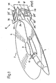
- the main components of the aircraft screwdriver are 1, the aircraft cell, 2, the main rotor, which contains the rotor head 3 and the rotor blades 4, used to generate vertical thrust, 6, the propeller, which is used to generate the forward thrust, and, in general, 7, to control the aircraft Vertical axis serving device called.
- a two common drive system 11 is provided for driving the main rotor 2 and the propeller 5 and connects to the main rotor 2 and the propeller 5 via a gear unit.
- the flight is in the region of the rear part Device cell 1, the yaw control 7, the pitch control 8, and the forward thrust-generating propeller 5 with its propeller working as a propeller 6, the propeller blades, which are generally known via a propeller adjustment mechanism, being designated by 9.
- a support frame 20 is provided on the aircraft tail for the pivotable reception of the jet or rudder 27 or 27 ', which at least to a large extent is composed of elements which are already present for the aircraft control or stabilization.
- the upwardly and downwardly extending sections 24 and 24 'of the fixed side stabilizing fin are provided.
- the sections 24 and 24 'of the side stabilization fin carry at their free end in a double-T arrangement an upper and lower horizontal stabilizer fin 22 and 22' (stabilization fin).
- a pair of supporting parts 25 or 25' and 26 or 26 ' which extend backwards in the horizontal direction and which overlap the propeller 6 at a short distance, are fastened.
- the upper and lower rudder supports 25, 26 and 25 ', 26' serve to accommodate the vertical pivot axes 29 and 29 'of the rudder or thruster 27 or 27' for an arrangement behind the propeller 6 in the propeller jet.
- the support frame 20 is thus formed by the side stabilization fins 24, 24 ', the height stabilization fins 22 and 22' fixed thereon in connection with the pivot axes 29 and 29 'for the thrusters 27 and 27', and those on the height stabilization fins 22 and 22 ' 22 'fastened supports 25 and 25' and 26 and 26 ', which are to be regarded as additional parts to the stabilization and control elements which are already present.
- the carrier 25 or 25 'and 26 or 26' are in the embodiment shown with respect to the flow within or at least for the most part within the cross-sectional area of the horizontal stabilizer fins 22 or 22 ', so that the arrangement of the carriers increases the Air resistance is avoided.
- the arrangement and design of the support frame 20 represents a torsion-resistant frame construction, through which the propeller or propeller jet remains undisturbed.
- the flow towards the thrusters 27 and 27 ' is also without interference from the support frame.
- a thruster is provided for the yaw control or the yaw moment compensation control on both sides of the longitudinal plane of the aircraft and thus the one with a large size, for example in the case of vane grids Serious number of cross-sectional constrictions or flow losses occurring largely avoided.
- the propeller wake flow thus remains largely undisturbed when the thrusters 27 and 27 'are in the neutral position, and even in the deflected position of the thrusters 27 and 27', the repercussions on the propeller by the rudders 27 and 27 'are also due to the relatively large distance relatively low.
- the thrusters 27 and 27 ' also lie completely or essentially within the wake of the propeller 6 in the deflection position.
- the flap 36 is here the gap 36 from the inside.
- the elevator 30 is pivotally mounted in the manner of a balancing rudder about a horizontal axis 31 on the upper part 24 of the side stabilization fin and at least to a substantial extent pivotable in front of the upper height control fin 22.
- the elevator 30 has a recess 32 at the rear and thus encompasses the height stabilizing fin 22 over part of its profile depth.
- the elevator 30 lies at least for the most part above the diameter of the propeller rotating circle D and extends laterally in the horizontal direction beyond the diameter of the propeller rotating circle D.
- the balance rudder arrangement and the arrangement of the elevator as a T-tail allows a position for the elevator 30, in which the rudder does not or only slightly disturb the propeller 5 or the propeller 6 even in the knocked-out state.
- the thrusters 27 and 27 ' which are designed as profiled high-lift flaps, are provided with a flow gap 35 of known mode of operation.
- the flow gap 35 can be closed by a flap 36 on the underside of the profile of the thrusters 27 and 27 '.
- the flap 36 closes the gap 36 from the inside under spring action and is automatically moved inward at high deflection angles of the rudders 27 and 27 'to release the gap 36 for the throughflow by means of the flow pressure.
- the torque is compensated for by the deflection of the thrusters 27 and 27 '.
- the remaining rotor counter torque is generated by the thrusters 27 and 27 '.
- the residual forward thrust which is generated in hover flight by the fact that the beam deflection (flow deflection) is less than 90 °, is compensated for by tilting the rotor 2 backwards. Since the main rotor 2 acts as a supporting screw, the rotor 2 has a more positive attitude than conventional helicopters.
- the propeller 6 in conjunction with the thrusters 27 and 27 'means that the aircraft can be greatly accelerated or decelerated practically without the fuselage tilting.
Landscapes
- Engineering & Computer Science (AREA)
- Mechanical Engineering (AREA)
- Aviation & Aerospace Engineering (AREA)
- Toys (AREA)
- Structures Of Non-Positive Displacement Pumps (AREA)
- Catching Or Destruction (AREA)
- Medicines Containing Material From Animals Or Micro-Organisms (AREA)
- Paper (AREA)
- Control Of Multiple Motors (AREA)
- Control Of Motors That Do Not Use Commutators (AREA)
Abstract
Description
- Die Erfindung betrifft Fluggeräte, insbesondere Drehflügelfluggeräte für hohe Vorwärtsfluggeschwindigkeiten, mit einem Vertikalschub erzeugenden Hauptrotor und einem vom Hauptrotor getrennt wirkenden Vorwärtsschub erzeugenden Propellerantrieb, sowie einer der Luftschraube des Propellerantriebes nachgeordneten Giersteuerung bzw. Giermomenten-Ausgleichssteuerung.
- Bei Hubschraubern wird in bekannter Weise Auftrieb und Vortrieb durch den Hauptrotor erzeugt. Der Rotor übernimmt dabei auch die Funktion der Lagesteuerung. Für den Drehmomentenausgleich und die Steuerung um die Hochachse dient ein Heckrotor, dessen Achse senkrecht zur Flugrichtung steht. Hubschrauber der genannten Art besitzen optimale Schwebeflugeigenschaften, sind aber Flächenflugzeugen im Hinblick auf Geschwindigkeit, Reichweite und Wirtschaftlichkeit unterlegen. Der Grund für die begrenzte Vorwärtsgeschwindigkeit liegt darin, dass sich bei zunehmender Vorwärtsgeschwindigkeit die Anströmgeschwindigkeit an den vorlaufenden Rotorblättern der Schallgeschwindigkeit annähert, wobei der Widerstand stark ansteigt. Bei den rücklaufenden Rotorblättern hingegen reisst die Strömung über grosse Bereiche der Rotorblätter infolge hoher Blattanstellwinkel ab und ausserdem werden bei hohen Vorwärtsfluggeschwindigkeiten grosse Bereiche der Rotorblätter von rückwärts angeströmt.
- Zur Erweiterung der Einsatzgrenzen von Drehflügelflugzeugen durch Steigerung der Marschfluggeschwindigkeit, sind eine Reihe unterschiedlicher Entwicklungen bekannt geworden, wie z.B. der Einsatz schnellflugfähiger Koaxialrotoren (advancing-blade concept), stillsetzbare Rotoren, mit Zirkulationssteuerung mittels Ausblasen von Luft aus Längsschlitzen an den Rotorblättern (X-wing-concept), auch zur Erzielung einer höherharmonischen Blattansteuerung, oder auch Rotoren mit gesteuerten, aerodynamischen Stellflächen an der Hinterkante der Rotorblätter.
- Um den Einsatzbereich von Hubschrauberrotoren zu höheren Fluggeschwindigkeiten hin zu erweitern, muss grundsätzlich die Fortschrittsgrad-Grenze überwunden werden, welche dann erreicht ist, wenn die rücklaufenden Blätter infolge Strömungsablösung den geforderten Auftrieb nicht mehr erzeugen können.
- Getrennt vom Hauptrotor wirkende Schuberzeuger für Vorwärtsschub und ebenso Giersteuereinrichtungen zum Ausgleich von Giermomenten an Drehflügelflugzeugen gehören zum allgemeinen Stand der Technik.
- Es ist dazu bekannt, die Anordnung eines Propellerantriebs auf dem Fluggeräterumpf eines Drehflügelflugzeuges mit einer Druckschraube vor dem Leitwerk.
- Es ist auch bekannt, bei Drehflüglern einen schwenkbaren Heckrotor zum Vorwärtsschub bzw. zum Drehmomentenausgleich und eine um eine senkrechte Achse schwenkbare Seitenleitwerksfläche anzuordnen, wobei die Leitwerksfläche stromauf vor dem Propeller liegt.
- Ein Aufbau bei Drehflüglern der genannten Art ist bekannt, der ebenfalls einen, um eine vertikale Achse schwenkbaren Propeller mit Druckschraube am Fluggeräteheck in Verbindung mit einer Seitensteuerfläche aufweist.
- Ferner ist es bekannt, am Fluggeräteheck von Drehflüglern einen Mantelpropeller zur Vortriebserzeugung mit in den Propellernachlaufströmung liegendem Seitenleitwerk anzuordnen.
- Ebenso ist eine Ablenkeinrichtung für die Propellernachlaufströmung in Verbindung mit einem ummantelten Propeller am Rumpfheck eines Drehflüglers bekannt, wobei die Ablenkeinrichtung ein schwenkbares Schaufelgitter enthält. Die im Profil symmetrischen Schaufeln des Ablenkgitters sind dabei in bezug auf ihre Wölbung veränderbar ausgeführt.
- Aufgabe der Erfindung ist es, einen Flugschrauber für hohe Marschgeschwindigkeiten durch besondere Anordnung und Ausbildung der Vorwärtsschub erzeugenden Einrichtung im Zusammenwirken mit einer Einrichtung zur Giersteuerung bzw. zum Giermomentenausgleich gegenüber dem Vertikalschub erzeugenden Hauptrotor sowohl hinsichtlich einer Verringerung der aerodynamischen Verluste als auch im Hinblick auf den Bauaufwand zu verbessern.
- Ferner soll die erfindungsgemässe Ausbildung das Auftreten schwer beherrschbarer Kreiselkräfte, hervorgerufen durch die Vorwärtsschub erzeugende Einrichtung, vermeiden und eine Herabsetzung des Strukturgewichts gegenüber bekannten Ausbildungen erreichen.
- Die gestellte Aufgabe ist erfindungsgemäss durch eine Ausbildung nach den Merkmalen des Hauptanspruchs und in weiterer vorteilhafter Ausgestaltung nach den Merkmalen weiterer, dem Hauptanspruch nachgeordneter Ansprüche gelöst.
- Bei dem erfindungsgemäss ausgebildeten Flugschrauber wird durch die Anordnung einer freifahrenden Luftschraube erreicht, dass die Strahlruder bzw. Seitenruder in einem Abschnitt des Propellernachlaufstrahls, indem erhöhte Strahlgeschwindigkeit herrscht, liegen.
- Die Strahlruder liegen günstig zu beiden Seiten der senkrechten Fluggeräte-Längsmittelebene im Propellernachlaufstrahl, ohne die z.B. bei Schaufelgittern auftretenden Strömungsverluste in Kauf nehmen zu müssen. Die Anordnung der Strahlruder, relativ weit hinter der Luftschraubendrehebene, vermeidet Beeinträchtigungen des Propellerschubstrahles und ermöglicht die Erzeugung relativ hoher Steuerkräfte.
- Schwer beherrschbare Kreiselmomente, wie sie bei schwenkbaren Propellern, auch bei ummantelten Propellern auftreten, sind hier vermieden.
- Die Strahlruder bzw. Seitenruder erlauben rasche Giersteuerbewegungen bzw. rasche Gierausgleichsbewegungen.
- Die Anordnung und Ausbildung des Trägergestells lässt eine Lage für die Luftschraube in einem axialen Abstand von der Höhensteuerfläche zu, die eine Beeinträchtigung des Propellerstrahls vermindert. Ferner ermöglicht das Trägergestell eine Reduzierung des Strukturgewichts durch Ausnutzung von ohnehin vorhandenden Elementen der Höhen- bzw. Seitensteuerung. Die Anordnung trägt auch dazu bei, die Ausbildung des Luftwiderstands durch das Trägergestell gering zu halten.
- Das Trägergestell in der erfindungsgemässen Ausbildung erlaubt die Anordnung des Höhenleitwerks so, dass das Leitwerk bei sämtlichen Ausschlagwinkeln den Propeller so wenig als möglich stört, und ferner liegen das Höhenruder und die Höhenstabilisierungsflosse weitgehend ausserhalb des Abwindstrahls des Hauptrotors, wodurch ungünstige Überlagerungsbeeinflussungen der Nicksteuerung durch den Hauptrotor-Abwindstrahls vermieden sind.
- Infolge der Ausbildung der Strahlruder als profilierte Hochauftriebsklappen, wird ein entgegen dem Drehmoment des Hauptrotors auch in neutraler Lage der Ruder wirksames Gegenmoment erzeugt und die Seitensteuerkräfte werden verstärkt.
- Die abschliessbaren Strömungsspalte der Ruder vermeiden bei grossen Ausschlagwinkeln eine Strömungsablösung.
- Das als Balanceruder ausgebildete Höhenruder ist mittels des Trägergestells ausserhalb des Abwindstrahls des Hauptrotors unter Vermeidung der Beeinträchtigung der Nicksteuerung angeordnet.
- Bei Fluggeräten der genannten Art ist noch von Bedeutung, dass im Schnellflug fast die gesamte Leistung der Triebwerke zur Vortriebserzeugung herangezogen wird, wobei praktisch keine Strahlablenkung auftritt. Das Restdrehmoment wird durch die entsprechend eingestellten Strahlruder erzeugt.
- Im Schwebeflug ist zwar die stärkste Strahlablenkung notwendig, aber die dabei erforderliche Leistung des Schuberzeugers ist nur gering.
- Der Restvorwärtsschub, der im Schwebeflug dadurch erzeugt wird, dass die Ablenkung des Abstroms des Schuberzeugers geringer als 90° ist, wird durch Anstellung bzw. Rotorneigung nach hinten kompensiert. Da der Hauptrotor als Tragschrauber wirkt, ist dieser ohnehin mehr positiv eingestellt, als bei konventionell aufgebauten Drehflügelfluggeräten.
- Die Anordnung des Propellers in Verbindung mit den Strahlrudern lässt vorteilhafter Weise rasche Änderungen des Schubvektors zu, im Gegensatz zu bekannten Anordnungen, bei denen der gesamte Propeller geschwenkt wird, was zu unerwünschten Kreiselmomenten führt.
- In der Zeichnung ist eine beispielsweise Ausführungsform gemäss der Erfindung dargestellt, die anhand der nachfolgenden Beschreibung näher erläutert ist.
- Es zeigen:
- Figur 1 eine perspektivische Gesamtansicht des Flugschraubers,
- Figuren 2 bis 2b eine Dreiseitenansicht des Fluggerätehecks mit der dem Propeller für die Vortriebserzeugung zugeordneten, mittels Strahlrudern arbeitenden Giersteuerung,
- Figur 2c eine Einzelheit der Steuerflächenausbildung gemäss Figuren 2 bis 2b und
- Figur 3 die Seitenansicht eines Flugschraubers in Verbindung mit dem Vorwärtsschuberzeuger und den Strahlrudern in Start- und Schwebefluglage.
- Gemäss Figur 1 sind als Hauptkomponenten des Flugschraubers mit 1 die Fluggerätezelle, mit 2 der den Rotorkopf 3 und die Rotorblätter 4 enthaltende, zur Erzeugung von Vertikalschub dienende Hauptrotor, mit 6 die zur Vorwärtsschuberzeugung dienende Luftschraube und allgemein mit 7 die zur Steuerung des Fluggerätes um die Hochachse dienende Einrichtung bezeichnet.
- Für den Antrieb des Hauptrotors 2 und den Propeller 5 ist eine beiden gemeinsame Antriebsanlage 11 vorgesehen, die über eine Getriebeeinheit an den Hauptrotor 2 und den Propeller 5 anschliesst.
- Gemäss den Einzelheiten des gezeigten Ausführungsbeispiels in den Figuren 2 bis 2c sind im Bereich des Heckteils der Fluggerätezelle 1 die Giersteuerung 7, die Nicksteuerung 8, sowie der vorwärtsschuberzeugende Propeller 5 mit seiner als Druckschraube arbeitenden Luftschraube 6 angeordnet, wobei die über ein Propellerverstellgetriebe allgemein bekannter Bauart verstellbaren Luftschraubenblätter mit 9 bezeichnet sind.
- Am Fluggeräteheck ist für die schwenkbare Aufnahme der Strahl- bzw. Seitenruder 27 bzw. 27' ein Trägergestell 20 vorgesehen, das sich zumindest zu einem wesentlichen Teil aus Elementen zusammensetzt, die für die Fluggerätesteuerung bzw. Stabilisierung ohnehin vorhanden sind.
- Am Fluggeräteheck sind in der senkrechten Fluggeräte-Längsmittelebene, die sich nach oben und unten erstreckenden Abschnitte 24 bzw. 24' der feststehenden Seitenstabilisierungsflosse vorgesehen. Die Abschnitte 24 bzw. 24' der Seitenstabilisierungsflosse tragen an ihrem freien Ende in Doppel-T-Anordnung eine obere bzw. untere Höhenleitwerksflosse 22 bzw. 22' (Stabilisierungsflosse).
- An der oberen bzw. unteren Höhenleitwerksflosse 22 bzw. 22' ist je ein Paar sich in horizontaler Richtung nach rückwärts erstreckender Trägerteile25 bzw. 25' und 26 bzw. 26' befestigt, die die Luftschraube 6 in geringem Abstand übergreifen.
- Die oberen bzw. unteren Seitenruderträger 25, 26 bzw. 25', 26' dienen zur Aufnahme der vertikalen Schwenkachsen 29 bzw. 29' der Seitenruder bzw. Strahlruder 27 bzw. 27' für eine Anordnung hinter der Luftschraube 6 im Luftschrauben-Nachlaufstrahl. Das Trägergestell 20 ist somit gebildet durch die Seitenstabilisierungsflosse 24, 24', die daran festen Höhenstabilisierungsflossen 22 bzw. 22' in Verbindung mit den Schwenkachsen 29 bzw. 29' für die Strahlruder 27 bzw. 27', sowie die an den Höhenstabilisierungsflossen 22 bzw. 22' befestigten Träger 25 bzw. 25' und 26 bzw. 26', die als zusätzliche Teile zu den ohnehin vorhandenen Stabilsierungs-und Steuerelementen anzusehen sind.
- Die Träger 25 bzw. 25' und 26 bzw. 26' liegen bei der gezeigten Ausführung in bezug auf die Anströmung innerhalb oder zumindest zum grössten Teil innerhalb der Querschnittsfläche der Höhenleitwerksflossen 22 bzw. 22', so dass durch die Anordnung der Träger eine Erhöhung des Luftwiderstandes vermieden ist.
- Die Anordnung und Ausbildung des Trägergestel1s20 stellt eine verwindungssteife Rahmenkonstruktion dar, durch die der Propeller- bzw. Luftschraubenstrahl ungestört bleibt. Ebenso ist auch die Anströmung der Strahlruder 27 bzw. 27' ohne Störung durch das Trägergestell.
- Bei der vorliegenden Ausführung sind für die Giersteuerung bzw. die Giermomentenausgleichssteuerung zu beiden Seiten der Fluggeräte-Längsmittelebene je ein Strahlruder vorgesehen und damit die z.B. bei Schaufelgittern mit einer grösseren Anzahl von Schaufeln auftretenden Querschnittsverengungen bzw. Strömungsverluste weitgehend vermieden.
- Die Luftschrauben-Nachlaufströmung bleibt somit bei in Neutralstellung befindlichen Strahlrudern 27 bzw. 27' weitgehend ungestört, und auch in Ablenkstellung der Strahlruder 27 bzw. 27' sind die Rückwirkungen auf die Luftschraube durch die Ruder 27 bzw. 27' auch infolge des relativ grossen Abstandes relativ gering.
- Bei der gezeigten Ausführung liegen die Strahlruder 27 bzw. 27' auch in Ausschlagstellung vollständig bzw. im wesentlichen innerhalb des Nachlaufstroms des Propellers 6.
- Die Klappe 36 liegt hierbei von innen her den Spalt 36 verDas Höhenruder 30 ist in der Art eines Balanceruders um eine horizontale Achse 31 schwenkbar am oberen Teil 24 der Seitenstabilisierungsflosse und zumindest zu einem wesentlichen Teil vor der oberen Höhensteuerflosse 22 schwenkbar gelagert. Das Höhenruder 30 weist rückwärtig eine Ausnehmung 32 auf und umgreift somit die Höhenstabilisierungsflosse 22 auf einem Teil ihrer Profiltiefe. Das Höhenruder 30 liegt in der gezeigten Anordnung zumindest zum grössten Teil oberhalb des Durchmessers des Propellerdrehkreises D und erstreckt sich seitlich in horizontaler Richtung über den Durchmesser des Propellerdrehkreises D hinaus. Die Balanceruderanordnung und die Anordnung des Höhenleitwerks als T-Leitwerk lässt eine Lage für das Höhenruder 30 zu, in der das Ruder auch im ausgeschlagenem Zustand den Propeller 5 bzw. die Luftschraube 6 nicht oder nur in geringem Maße stört.
- Gemäss Figur 2c sind die Strahlruder 27 bzw. 27', die als profilierte Hochauftriebsklappen ausgelegt sind, mit einem Strömungsspalt 35 bekannter Wirkungsweise versehen. Der Strömungsspalt 35 ist durch eine-Klappe 36 an der Unterseite des Profils der Strahlruder 27 bzw. 27' abschliessbar.
- Die Klappe 36 verschliesst hierbei unter Federwirkung von innen her den Spalt 36 und wird bei hohen Ausschlagwinkeln der Ruder 27 bzw. 27' zur Freigabe des Spaltes 36 nach innen für die Durchströmung mittels des Strömungsdruckes selbsttätig bewegt.
- Die Wirkungsweise des beschriebenen Flugschraubers ist wie folgt:
- Der Vortrieb des Fluggerätes sowie der Drehmomentenausgleich erfolgt mittels des Druckpropellers 5 und den diesem zugeordneten Seitenrudern 27 bzw. 27' . Ein Vorteil der Anordnung des Propellers 5 bzw. der Luftschraube 6 in Verbindung mit den Strahlrudern 27 bzw. 27' beruht darauf, dass eine rasche Änderung des Schubvektors bei Ausschlag der Strahlruder ermöglicht ist.
- Im Schwebeflug erfolgt der Drehmomentenausgleich durch den Ausschlag der Strahlruder 27 bzw. 27' . Im Reiseflug wird annähernd die gesamte, von der Antriebsanlage 11 erzeugte Leistung auf den Druckpropeller 5 übertragen. Dabei wird das restliche Rotorgegendrehmoment durch die Strahlruder 27 bzw. 27' erzeugt. Der Restvorwärtsschub, der im Schwebeflug dadurch erzeugt wird, dass die Strahlablenkung (Strömungsablenkung) geringer als 90° ist, wird durch Anstellung, das heisst durch Neigung des Rotors 2 nach hinten kompensiert. Da der Hauptrotor 2 als Tragschraube wirkt, weist der Rotor 2 eine mehr positive Einstellung gegenüber konventionellen Hubschraubern auf.
- Neben der Vortriebserzeugung im Reiseflug-wird mittels der Luftschraube 6 in Verbindung mit den Strahlrudern 27 bzw. 27' erreicht, dass das Fluggerät praktisch ohne Rumpfneigung stark beschleunigt bzw. stark verzögert werden kann.
Claims (17)
dadurch gekennzeichnet , dass
Applications Claiming Priority (2)
| Application Number | Priority Date | Filing Date | Title |
|---|---|---|---|
| DE3539338 | 1985-11-06 | ||
| DE3539338 | 1985-11-06 |
Publications (3)
| Publication Number | Publication Date |
|---|---|
| EP0229896A2 true EP0229896A2 (de) | 1987-07-29 |
| EP0229896A3 EP0229896A3 (en) | 1988-07-20 |
| EP0229896B1 EP0229896B1 (de) | 1990-09-19 |
Family
ID=6285292
Family Applications (2)
| Application Number | Title | Priority Date | Filing Date |
|---|---|---|---|
| EP86114933A Expired - Lifetime EP0229896B1 (de) | 1985-11-06 | 1986-10-27 | Fluggerät, insbesondere Drehflügelfluggerät in der Art eines Flugschraubers für höhere Fluggeschwindigkeiten |
| EP86114934A Expired - Lifetime EP0223117B1 (de) | 1985-11-06 | 1986-10-27 | Zirkulationsgesteuertes Rotorsystem für Luftfahrzeuge |
Family Applications After (1)
| Application Number | Title | Priority Date | Filing Date |
|---|---|---|---|
| EP86114934A Expired - Lifetime EP0223117B1 (de) | 1985-11-06 | 1986-10-27 | Zirkulationsgesteuertes Rotorsystem für Luftfahrzeuge |
Country Status (5)
| Country | Link |
|---|---|
| US (2) | US4726547A (de) |
| EP (2) | EP0229896B1 (de) |
| JP (2) | JPS62168793A (de) |
| DE (2) | DE3674369D1 (de) |
| IN (2) | IN169764B (de) |
Cited By (2)
| Publication number | Priority date | Publication date | Assignee | Title |
|---|---|---|---|---|
| EP2409917A1 (de) | 2010-07-20 | 2012-01-25 | Eurocopter | Verfahren und Luftfahrzeug mit Drehfahrwerk, das mit einem Stabilisationsmittel zur Minimierung des attitude hump -Phänomens ausgestattet ist |
| EP2878536A1 (de) | 2013-11-29 | 2015-06-03 | AIRBUS HELICOPTERS DEUTSCHLAND GmbH | Erweiterter Steigungsstabilisator |
Families Citing this family (27)
| Publication number | Priority date | Publication date | Assignee | Title |
|---|---|---|---|---|
| US5405104A (en) * | 1993-01-04 | 1995-04-11 | Pande; John B. | Stopped rotor aircraft utilizing a flipped airfoil X-wing |
| GB9317294D0 (en) * | 1993-08-19 | 1993-10-20 | Westland Helicopters | Circulation control aerofoils |
| US5601257A (en) * | 1994-08-11 | 1997-02-11 | Benchmark Corporation | Air vehicle yaw control system |
| US5813625A (en) * | 1996-10-09 | 1998-09-29 | Mcdonnell Douglas Helicopter Company | Active blowing system for rotorcraft vortex interaction noise reduction |
| JP3051357B2 (ja) * | 1997-03-26 | 2000-06-12 | 株式会社コミュータヘリコプタ先進技術研究所 | 主ロータトルク補正装置 |
| US6234751B1 (en) | 1997-06-05 | 2001-05-22 | Mcdonnell Douglas Helicopter Co. | Oscillating air jets for reducing HSI noise |
| US6543719B1 (en) | 1997-06-05 | 2003-04-08 | Mcdonnell Douglas Helicopter Co. | Oscillating air jets for implementing blade variable twist, enhancing engine and blade efficiency, and reducing drag, vibration, download and ir signature |
| US5984635A (en) * | 1998-08-24 | 1999-11-16 | Keller; Merrill Manson | Keller pressure jet rotor system |
| US6478541B1 (en) | 2001-08-16 | 2002-11-12 | The Boeing Company | Tapered/segmented flaps for rotor blade-vortex interaction (BVI) noise and vibration reduction |
| GB2457685B (en) * | 2008-02-21 | 2012-06-27 | David Hostettler Wain | Vertically flexible swash plate |
| US9133819B2 (en) | 2011-07-18 | 2015-09-15 | Kohana Technologies Inc. | Turbine blades and systems with forward blowing slots |
| US9061760B2 (en) | 2012-08-02 | 2015-06-23 | Bell Helicopter Textron Inc. | Independent blade control system with rotary blade actuator |
| US9162760B2 (en) | 2012-08-02 | 2015-10-20 | Bell Helicopter Textron Inc. | Radial fluid device with multi-harmonic output |
| US8973864B2 (en) | 2012-08-02 | 2015-03-10 | Bell Helicopter Textron Inc. | Independent blade control system with hydraulic cyclic control |
| US9376205B2 (en) | 2012-08-02 | 2016-06-28 | Bell Helicopter Textron Inc. | Radial fluid device with variable phase and amplitude |
| US8857757B2 (en) | 2012-08-02 | 2014-10-14 | Bell Helicopter Textron Inc. | Independent blade control system with hydraulic pitch link |
| US9528375B2 (en) * | 2012-11-30 | 2016-12-27 | Sikorsky Aircraft Corporation | Non-uniform blade distribution for rotary wing aircraft |
| CN103803071B (zh) * | 2014-01-24 | 2016-08-17 | 兰州神龙航空科技有限公司 | 工程型旋翼式无人飞行器 |
| EP3201081A4 (de) * | 2014-09-30 | 2018-04-18 | Sikorsky Aircraft Corporation | Drehflüglerkonfiguration und verfahren zur drehflüglerkonstruktion |
| CN105620715B (zh) * | 2016-04-07 | 2018-02-02 | 珠海紫燕无人飞行器有限公司 | 无人直升机 |
| CN106314787B (zh) * | 2016-09-08 | 2019-05-07 | 锐合防务技术(北京)有限公司 | 飞行器 |
| DE102019118023B3 (de) * | 2019-07-04 | 2020-07-23 | Dr. Ing. H.C. F. Porsche Aktiengesellschaft | Luftfahrzeug |
| DE102019118024B4 (de) * | 2019-07-04 | 2022-11-10 | Dr. Ing. H.C. F. Porsche Aktiengesellschaft | Luftfahrzeug |
| EP3842337B1 (de) | 2019-12-23 | 2022-01-26 | LEONARDO S.p.A. | Hubschrauber, hubschrauber-kit und zugehöriges rekonfigurationsverfahren |
| WO2021251807A1 (ru) * | 2020-06-11 | 2021-12-16 | Алдан Асанович САПАРГАЛИЕВ | Тяговые поверхности аппарата самоперемещения |
| JP7610449B2 (ja) * | 2021-03-29 | 2025-01-08 | 本田技研工業株式会社 | 航空機 |
| CN218971505U (zh) * | 2022-08-08 | 2023-05-05 | 广东澳运科技有限公司 | 一种便于组装的风扇 |
Family Cites Families (30)
| Publication number | Priority date | Publication date | Assignee | Title |
|---|---|---|---|---|
| US1609978A (en) * | 1926-04-10 | 1926-12-07 | Wagner Rudolf | Counter propeller for air propeller-driven craft |
| US2081957A (en) * | 1933-09-01 | 1937-06-01 | Roche Jean Alfred | Dynamic balance of control surfaces |
| US2547255A (en) * | 1942-12-05 | 1951-04-03 | Bruel Andre Aime Lucien | Helicopter with automatic antitorque vane |
| FR978969A (fr) * | 1942-12-29 | 1951-04-20 | Perfectionnement aux avions à ailes à fente hypersustentatrice | |
| US2410545A (en) * | 1943-03-15 | 1946-11-05 | David W Main | Pitch control mechanism for rotors of rotary wing aircraft |
| DE907625C (de) * | 1951-05-29 | 1954-03-29 | Alvaro Da Silva Costa | Strahlantriebsvorrichtung fuer Rotoren, insbesondere fuer Hubschrauber, mit zentraler Gasverteilerkammer |
| FR1178374A (fr) * | 1956-09-05 | 1959-05-06 | Rhein West Flug Fischer & Comp | Perfectionnements apportés aux avions avec empennage en forme de tau |
| US3029048A (en) * | 1959-09-28 | 1962-04-10 | Brooks Earnest | Helicopter |
| US3138349A (en) * | 1962-01-15 | 1964-06-23 | Piasecki Aircraft Corp | Rotary wing aircraft tail assembly and controls |
| GB1066223A (en) * | 1964-05-29 | 1967-04-26 | Power Jets Res & Dev Ltd | Helicopter lift control mechanism |
| FR1400834A (fr) * | 1964-07-09 | 1965-05-28 | Fiat Spa | Amélioration aux aérodynes |
| GB1073418A (en) * | 1964-10-20 | 1967-06-28 | Power Jeis Res And Dev Ltd | Helicopter rotor |
| US3260482A (en) * | 1964-12-03 | 1966-07-12 | Piasecki Aircraft Corp | Directional control assembly |
| US3409248A (en) * | 1965-10-22 | 1968-11-05 | Harvard J. Bryan | Rotary winged aircraft with drag propelling rotors and controls |
| US3417946A (en) * | 1967-12-29 | 1968-12-24 | Lockheed Aircraft Corp | T-tail construction for aircraft |
| US3554662A (en) * | 1968-01-25 | 1971-01-12 | Fairchild Hiller Corp | Reverse velocity rotor and rotorcraft |
| US3713750A (en) * | 1970-12-07 | 1973-01-30 | Us Navy | Circulation control rotor system |
| US3816019A (en) * | 1972-08-24 | 1974-06-11 | Us Navy | Cam type air control valves |
| US3862811A (en) * | 1973-08-14 | 1975-01-28 | Us Navy | Streamlined x-y-z cone valve |
| US3904313A (en) * | 1973-11-05 | 1975-09-09 | Henry J Bernaerts | Higher harmonics hub valve |
| US3921942A (en) * | 1974-07-01 | 1975-11-25 | Gen Dynamics Corp | Rudder boundary layer control device |
| US4132500A (en) * | 1977-05-18 | 1979-01-02 | The United States Of America As Represented By The Secretary Of The Navy | Controllable and programmable fluid flow modulation system |
| US4242044A (en) * | 1979-07-11 | 1980-12-30 | The United States Of America As Represented By The Secretary Of The Navy | Compensating structure for circulation control rotor pneumatic valve |
| US4421489A (en) * | 1981-04-20 | 1983-12-20 | John Van Veldhuizen | Propeller driven vehicle with forward and reverse control air rudders |
| US4493361A (en) * | 1981-12-07 | 1985-01-15 | Gus Sevastakis | Continuous casting apparatus |
| US4507050A (en) * | 1983-12-09 | 1985-03-26 | United Technologies Corporation | Pneumatic valve control for circulation control aircraft |
| US4583704A (en) * | 1983-12-27 | 1986-04-22 | United Technologies Corporation | Pneumatic system structure for circulation control aircraft |
| US4534702A (en) * | 1983-12-27 | 1985-08-13 | United Technologies Corporation | Pneumatic control valve actuator computer control arrangement |
| US4573871A (en) * | 1984-08-29 | 1986-03-04 | The United States Of America As Represented By The Secretary Of The Army | X-Wing aircraft circulation control |
| US4655685A (en) * | 1985-12-16 | 1987-04-07 | United Technologies Corporation | Helicopter main rotor blade having a short span slot near the tip end |
-
1986
- 1986-10-27 DE DE8686114933T patent/DE3674369D1/de not_active Expired - Fee Related
- 1986-10-27 DE DE8686114934T patent/DE3674155D1/de not_active Expired - Fee Related
- 1986-10-27 EP EP86114933A patent/EP0229896B1/de not_active Expired - Lifetime
- 1986-10-27 EP EP86114934A patent/EP0223117B1/de not_active Expired - Lifetime
- 1986-11-05 US US06/927,660 patent/US4726547A/en not_active Expired - Fee Related
- 1986-11-05 US US06/927,656 patent/US4799859A/en not_active Expired - Fee Related
- 1986-11-06 JP JP61264401A patent/JPS62168793A/ja active Pending
- 1986-11-06 JP JP61264400A patent/JPS62155199A/ja active Pending
- 1986-11-20 IN IN1011/DEL/86A patent/IN169764B/en unknown
- 1986-11-20 IN IN1015/DEL/86A patent/IN168053B/en unknown
Cited By (7)
| Publication number | Priority date | Publication date | Assignee | Title |
|---|---|---|---|---|
| EP2409917A1 (de) | 2010-07-20 | 2012-01-25 | Eurocopter | Verfahren und Luftfahrzeug mit Drehfahrwerk, das mit einem Stabilisationsmittel zur Minimierung des attitude hump -Phänomens ausgestattet ist |
| FR2962972A1 (fr) * | 2010-07-20 | 2012-01-27 | Eurocopter France | Procede et aeronef a voilure tournante muni d'un moyen de stabilisation minimisant le phenomene de bosse d'assiette |
| US8985500B2 (en) | 2010-07-20 | 2015-03-24 | Airbus Helicopters | Method of minimizing the attitude hump phenomenon and a rotary wing aircraft provided with stabilizer means therefor |
| EP2878536A1 (de) | 2013-11-29 | 2015-06-03 | AIRBUS HELICOPTERS DEUTSCHLAND GmbH | Erweiterter Steigungsstabilisator |
| KR20150062948A (ko) | 2013-11-29 | 2015-06-08 | 에어버스 헬리콥터스 도이칠란트 게엠베하 | 진보된 피치 스태빌라이저 |
| US9381995B2 (en) | 2013-11-29 | 2016-07-05 | Airbus Helicopters Deutschland GmbH | Advanced pitch stabilizer |
| KR101723666B1 (ko) | 2013-11-29 | 2017-04-05 | 에어버스 헬리콥터스 도이칠란트 게엠베하 | 진보된 피치 스태빌라이저를 갖는 회전날개 항공기 |
Also Published As
| Publication number | Publication date |
|---|---|
| EP0229896A3 (en) | 1988-07-20 |
| IN169764B (de) | 1991-12-21 |
| EP0223117A3 (en) | 1988-10-12 |
| EP0223117B1 (de) | 1990-09-12 |
| DE3674155D1 (de) | 1990-10-18 |
| JPS62155199A (ja) | 1987-07-10 |
| EP0223117A2 (de) | 1987-05-27 |
| US4799859A (en) | 1989-01-24 |
| IN168053B (de) | 1991-01-26 |
| EP0229896B1 (de) | 1990-09-19 |
| JPS62168793A (ja) | 1987-07-25 |
| DE3674369D1 (de) | 1990-10-25 |
| US4726547A (en) | 1988-02-23 |
Similar Documents
| Publication | Publication Date | Title |
|---|---|---|
| EP0229896B1 (de) | Fluggerät, insbesondere Drehflügelfluggerät in der Art eines Flugschraubers für höhere Fluggeschwindigkeiten | |
| DE60210512T2 (de) | Senkrecht startendes und landendes flugzeug | |
| DE102015207445B4 (de) | Tragfläche für ein Luftfahrzeug und Luftfahrzeug | |
| EP0416590A2 (de) | Flugzeug mit um eine Querachse kippbaren Triebwerksgondeln | |
| DE60101477T2 (de) | Ringflügelflugzeug | |
| DE60002148T2 (de) | Senkrechtstarter mit variabler Flügelpfeilstellung | |
| EP0667283B1 (de) | Kombinations-luftfahrzeug | |
| EP1943143B1 (de) | Flugzeug | |
| DE69414691T2 (de) | V/stol-flugzeug mit einem freien flügelanstellwinkel und mit einem schwenkbaren heckausleger | |
| CH685692A5 (de) | Fluggerät. | |
| DE2922059A1 (de) | Verbundflugzeug | |
| DE102021133301B3 (de) | VTOL-Luftfahrzeug mit batterieelektrischem Antrieb und Verbrennungsmotor | |
| DE112020007562T5 (de) | Flügelkonsole eines vertikal startenden und landenden Flugzeugs sowie Flugzeug mit einem solchen Flügel | |
| DE3636454C2 (de) | ||
| DE4237873C2 (de) | Senkrechtstartflugzeug mit aktiver Auftriebserzeugung und aktiver Steuermomenterzeugung | |
| EP4408740B1 (de) | Elektrisch angetriebenes fluggerät | |
| EP4237329B1 (de) | Antriebseinheit für einen drehflügler und drehflügler | |
| DE4443731A1 (de) | V/STOL-Flugzeug | |
| DE1056481B (de) | Flugzeug mit Ringfluegel und in diesem eingebauter Vortriebseinrichtung | |
| EP1685024B1 (de) | Luftfahrzeug | |
| DE10256916B4 (de) | Hubschrauber | |
| DE102019119933B3 (de) | Drehflügler mit einem für hohe Fluggeschwindigkeit optimierten Hauptrotor | |
| DE2606424A1 (de) | Pendel - rotorsteuerung | |
| DE102023108980B3 (de) | Flugzeug | |
| DE102015017425B3 (de) | Tragfläche für ein Luftfahrzeug und Luftfahrzeug |
Legal Events
| Date | Code | Title | Description |
|---|---|---|---|
| PUAI | Public reference made under article 153(3) epc to a published international application that has entered the european phase |
Free format text: ORIGINAL CODE: 0009012 |
|
| AK | Designated contracting states |
Kind code of ref document: A2 Designated state(s): DE FR GB IT |
|
| PUAL | Search report despatched |
Free format text: ORIGINAL CODE: 0009013 |
|
| AK | Designated contracting states |
Kind code of ref document: A3 Designated state(s): DE FR GB IT |
|
| 17P | Request for examination filed |
Effective date: 19880817 |
|
| 17Q | First examination report despatched |
Effective date: 19890623 |
|
| GRAA | (expected) grant |
Free format text: ORIGINAL CODE: 0009210 |
|
| AK | Designated contracting states |
Kind code of ref document: B1 Designated state(s): DE FR GB IT |
|
| PGFP | Annual fee paid to national office [announced via postgrant information from national office to epo] |
Ref country code: FR Payment date: 19900928 Year of fee payment: 5 |
|
| GBT | Gb: translation of ep patent filed (gb section 77(6)(a)/1977) | ||
| PGFP | Annual fee paid to national office [announced via postgrant information from national office to epo] |
Ref country code: GB Payment date: 19901022 Year of fee payment: 5 |
|
| REF | Corresponds to: |
Ref document number: 3674369 Country of ref document: DE Date of ref document: 19901025 |
|
| ITTA | It: last paid annual fee | ||
| PGFP | Annual fee paid to national office [announced via postgrant information from national office to epo] |
Ref country code: DE Payment date: 19901129 Year of fee payment: 5 |
|
| ET | Fr: translation filed | ||
| ITF | It: translation for a ep patent filed | ||
| PLBE | No opposition filed within time limit |
Free format text: ORIGINAL CODE: 0009261 |
|
| STAA | Information on the status of an ep patent application or granted ep patent |
Free format text: STATUS: NO OPPOSITION FILED WITHIN TIME LIMIT |
|
| 26N | No opposition filed | ||
| PG25 | Lapsed in a contracting state [announced via postgrant information from national office to epo] |
Ref country code: GB Effective date: 19911027 |
|
| GBPC | Gb: european patent ceased through non-payment of renewal fee | ||
| PG25 | Lapsed in a contracting state [announced via postgrant information from national office to epo] |
Ref country code: FR Effective date: 19920630 |
|
| PG25 | Lapsed in a contracting state [announced via postgrant information from national office to epo] |
Ref country code: DE Effective date: 19920701 |
|
| REG | Reference to a national code |
Ref country code: FR Ref legal event code: ST |
|
| PG25 | Lapsed in a contracting state [announced via postgrant information from national office to epo] |
Ref country code: IT Free format text: LAPSE BECAUSE OF NON-PAYMENT OF DUE FEES;WARNING: LAPSES OF ITALIAN PATENTS WITH EFFECTIVE DATE BEFORE 2007 MAY HAVE OCCURRED AT ANY TIME BEFORE 2007. THE CORRECT EFFECTIVE DATE MAY BE DIFFERENT FROM THE ONE RECORDED. Effective date: 20051027 |