EP0229590A1 - Low-voltage distribution - Google Patents
Low-voltage distribution Download PDFInfo
- Publication number
- EP0229590A1 EP0229590A1 EP86810538A EP86810538A EP0229590A1 EP 0229590 A1 EP0229590 A1 EP 0229590A1 EP 86810538 A EP86810538 A EP 86810538A EP 86810538 A EP86810538 A EP 86810538A EP 0229590 A1 EP0229590 A1 EP 0229590A1
- Authority
- EP
- European Patent Office
- Prior art keywords
- ieg
- plug
- busbars
- busbar
- voltage distribution
- Prior art date
- Legal status (The legal status is an assumption and is not a legal conclusion. Google has not performed a legal analysis and makes no representation as to the accuracy of the status listed.)
- Granted
Links
Images


Classifications
-
- H—ELECTRICITY
- H02—GENERATION; CONVERSION OR DISTRIBUTION OF ELECTRIC POWER
- H02B—BOARDS, SUBSTATIONS OR SWITCHING ARRANGEMENTS FOR THE SUPPLY OR DISTRIBUTION OF ELECTRIC POWER
- H02B1/00—Frameworks, boards, panels, desks, casings; Details of substations or switching arrangements
- H02B1/015—Boards, panels, desks; Parts thereof or accessories therefor
- H02B1/04—Mounting thereon of switches or of other devices in general, the switch or device having, or being without, casing
- H02B1/056—Mounting on plugboards
-
- H—ELECTRICITY
- H02—GENERATION; CONVERSION OR DISTRIBUTION OF ELECTRIC POWER
- H02B—BOARDS, SUBSTATIONS OR SWITCHING ARRANGEMENTS FOR THE SUPPLY OR DISTRIBUTION OF ELECTRIC POWER
- H02B1/00—Frameworks, boards, panels, desks, casings; Details of substations or switching arrangements
- H02B1/20—Bus-bar or other wiring layouts, e.g. in cubicles, in switchyards
Definitions
- the present invention relates to a low-voltage distribution with installation built-in devices (hereinafter referred to as IEG) detachably connected to at least one busbar, a busbar system and means for feeding the busbars.
- IEG installation built-in devices
- Low-voltage switchgear which includes the IEG in particular, is used in large quantities in distributions, especially for rated currents up to 63 A.
- the IEG includes, for example, fuses, miniature circuit breakers, residual current circuit breakers, motor circuit breakers, main switches, other modular devices and contactors.
- the IEG which are assembled individually or combined into several devices, take over the switching and / or protection of the outgoing lines and thus the consumers connected to them.
- an upstream overcurrent protection device with e.g. 100 or 200 A nominal current to supply a larger number of IEGs with electrical energy.
- connection systems created by American manufacturers are designed for the corresponding needs. A combination of individual IEGs with those of another manufacturer is not possible.
- IEG dimensions and fastenings were standardized very early on. Standardized 35 mm wide top-hat rails are used to attach the IEG with a snap mechanism.
- the Swiss electrotechnical association for example, has specified the European standard for 35 mm wide top-hat rails for snap mounting of IEG in the standard SEV-EN 50 022 (1978).
- the envelope mass of the IEG i.e. the external dimensions of their housings are specified in DIN 43 880.
- busbar brackets are used to connect the individual IEGs to busbars with different cross-sections. With the help of the busbar bracket, individually designed IEG feeds can be carried out.
- all known solutions have the disadvantage of time-consuming and complex assembly. When setting up a low-voltage distribution, a large number of connection screws must be tightened. Furthermore, great care must be taken to ensure that there is a sufficient distance between connections with different potentials.
- the input terminal of the IEG is designed as a flexible connection with a screw connection to suitably pre-assembled busbars.
- the feed can be three-phase, but the phase sequence is fixed.
- the neutral conductor is not included in the busbar system.
- the inventors have set themselves the task of creating a low-voltage distribution of the type described at the outset, which is simple to assemble, saves costs in the procurement of additionally required individual parts and is flexible in use, and allows warehouse management at a low investment level.
- the object is achieved in that -
- the IEG in the area of its rear side of the housing is equipped with a self-resilient plug-in contact part, which can be positioned in a floating manner in a guide channel running in the longitudinal direction of the IEG, and takes the electrical current from a busbar - forming a contact connection - and conducts it into the IEG .
- a plug base which is open on at least one side and consists of electrically insulating material and which holds the busbars, can be fastened to a base and essentially consists of ribs running in the longitudinal and transverse directions, the transverse ribs running at intervals in accordance with the standard dimensions of the IEG Pick up busbars in recessed grooves, and -
- the means for feeding the busbars are connected at a freely selectable point.
- the position of the plug contact part can be adapted to the position of the busbars by appropriate positioning. Because the plug contact part can be positioned in a floating manner, it can absorb dilations or contractions caused by temperature fluctuations.
- the guide for the plug-in contact part arranged on the back of the IEG housing includes all solutions known to the mechanic with locking options.
- a guide channel with vertical side walls that is open on one side is expediently left open.
- open guide grooves run in the side walls of the guide channel on the same side of the IEG, into which the guide plate (s) of a plug-in contact part, which is inserted laterally, engage / engage.
- known device (s) are / are arranged in the guide channel or in the guide grooves, which serve for the floating locking of the plug contact part.
- the floating positioning can be generated, for example, in that the plate of the plug-in contact part inserted into the grooves is of a smaller thickness than the width of the groove.
- the plug contact part is expediently designed as a so-called plug tulip, the shape of the two preferably self-resilient legs being adapted to the geometric shape of the busbar cross section.
- This can take any convenient shape, but is preferably rectangular, square or round.
- the plug-in tulips are made of a material with good electrical conductivity, such as copper, brass or aluminum.
- the plug-in base with the inserted busbars preferably consists of an easily sprayable plastic, in particular a polyamide, polyethylene or polypropylene.
- This plug-in base preferably has a modular structure in which the longitudinal and transverse ribs are arranged at regular intervals. The plug contact parts can be clamped onto the busbars between the cross ribs.
- one long side of the plug-in base can be equipped with abutments, which at the start of plugging the IEG into a correspondingly shaped groove, which in the area of the IEG housing rear side from that of the guide channel recessed opposite narrow side is introduced.
- two protruding lugs can be arranged on the IEG.
- the second long side of the plug-in base is provided with snap hooks which are formed on or attached to it and which engage with the projecting lugs.
- the distance between the snap hooks corresponds, for example, to the grid of the transverse ribs.
- the snap hooks expediently have an angled lever which can be pivoted about an axis and with which the latched lugs of the snap hooks can be lifted off.
- An optionally applied, forward-facing bar that extends over the entire length of the plug-in base is intended to accommodate lettering.
- the IEG on the front of the housing and the bar mentioned are labeled at the same time. This ensures that when an IEG is removed, the relevant location is marked and the device can be used again in the same location without any problems.
- the plug-in base with its additional components and the busbars is therefore an element kit that can be assembled as required.
- Power can be supplied to the busbars in a variety of ways: - Separate supply terminals are used, which are arranged at one end of the busbars, but also at a suitable location inside the socket. - An infeed block, which preferably consists of the same material as the plug-in base and is constructed on the same principle, is used. This feed block can be snapped on like the IEG, so it can be installed and removed anywhere in the socket without tools.
- the feeder block contains a number of feeder terminals corresponding to the number of rails, the claws of which are in contact with the busbars.
- One or more normally designed IEGs can feed current via one pole each into a busbar / busbars by means of a plug-in contact part, without the basic function of the IEG being impaired.
- a special feed terminal is well suited in all embodiments of the feed.
- This consists of a U-shaped housing with a base through which a screw passes.
- a large opening is preferably punched out from each of the two legs of the U-shaped housing.
- This allows the connecting conductor to be inserted into the feed terminal from four directions and clamped in place with the screw that acts on a support plate on the end.
- the legs of the U-shaped housing continue as clamping claws. At the transition of the housing legs into the clamping claws, an axis is arranged on which an angled lever can be pivoted. This lever forms on the one hand the opposite clamping claw and on the other hand the support plate on which the connection conductor rests.
- both the connection conductor can be fixed and the feed terminal can be fixed on a busbar in a contact-locking manner.
- a spring force can act on the clamps to position the feed terminal on a busbar.
- the IEG can be installed without tools, just by plugging it on. They snap into place and can be removed without tools.
- the IEG can be easily replaced when converting the consumer.
- the busbar systems ie the plug-in base with the busbars, can be snapped together using the modular principle. Additional bases can also be added using the modular principle.
- Only one variant per IEG type - and not several with plug-in contact parts in different positions - has to be manufactured and kept in stock.
- the live busbars are automatically covered to the front and removed from the risk of contact.
- the IEG according to the present invention can also be used for conventional low-voltage distributions by providing the cutout required for top-hat rails.
- a clamp or locking clamp is inserted into the grooves usually provided for a plug contact part sets, which can snap into the top-hat rail.
- such an IEG must still have an input terminal. If the IEG is used polyvalently, it is equipped with an input terminal which is either connected to the plug contact part via a flexible conductor or to which - in the absence of a plug contact part - the connecting conductor to the busbar or the connecting wire is clamped.
- plug contact part or a clamping or locking bracket With input terminal and positioning devices for a plug contact part or a clamping or locking bracket, it is possible to assemble IEG without the mentioned parts or to store them. Depending on the customer's requirements, the plug-in contact part or the clamping or locking clamp can be used immediately before delivery or even only by the user himself.
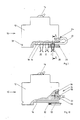
- the IEG 10 shown in FIG. 1 is surrounded by a housing 12 with standardized external dimensions.
- a shift lever 14 is visible on the front of the IEG.
- On the back of the housing a dovetail cutout 16 on the left-hand side can be seen for snapping onto a top hat rail, not shown.
- the recess 16 has no function in the IEG 10 according to FIG. 1 and would in principle not be necessary.
- a plug-in tulip 20 is arranged in position I - positioned floating in a guide channel 18 - .
- the plug-in tulip is connected via a flexible conductor 22 to an input terminal 24 which is designed as in conventional embodiments and feeds the current. From there, the electricity is conducted into the interior of the IEG.
- the housing 12 can be closed at the location of the input terminal 24 shown. In this case, the electrical current is fed from the plug tulip 20 directly into the interior of the IEG.
- a nose 26 is provided, projecting on one side, and a groove 28 on the other side.
- the guide channel 18 for the plug-in tulip 20 is shown in detail in FIG. 2.
- two parallel guide grooves 32 can be seen, into which the guide plate 34, which in the present case is integrally formed with the plug-in tulip 20, is inserted with the locking slide 36.
- This locking slide is shown in detail in Fig. 3, it consists of an elastic plastic, for example polyethylene, and has in the present case on both of them Legs 38 have three notches 40 each, which correspond approximately in width and depth to the dimensions of the guide plate 34 of the plug tulip 20.
- a locking hook 44 is formed on the connecting piece 42 of the two legs 38.
- the two relatively thin guide flanges 46 are also cut out at three locations, corresponding to the dimensions of the notches 40 of the locking slide 36. If the locking slide is positioned in such a way that the notches 40 lie below the cutouts in the guide flanges 46, guide plates 34 of the plug-in tulip 20 can be inserted into the notches 40 of the locking slide from the front. If the locking slide is moved in the longitudinal direction of the guide channel 18, the guide plates 34 and thus the plug-in tulip 20 itself are fixed by the locking slide 36 and the guide flanges 46. However, that the plate 34 has some play, the plug-in tulip 20 is locked in a floating manner. The locking hook 44 of the locking slide 36 can be locked by inserting it into a correspondingly recessed hole.
- the busbars which are inserted into correspondingly shaped recesses in the transverse ribs 58, comprise the three phases sen L1, L2 and L3, the neutral conductor N, the auxiliary contact conductor H and the signal contact conductor S.
- open, horizontal T-shaped grooves 62 for receiving an additional base 64 are recessed, which is shown in FIG. 6 is indicated by an arrow 66.
- the additional base 64 contains the busbars for the earth PE and the neutral conductor N, likewise held in the form of the crosspieces 58.
- plug bases 54 It is not only possible to receive additional base 64 from one plug base 54, but a plurality of plug bases 54 can be joined to one another in the longitudinal direction of the conductors in a known manner.
- the individual plug-in bases are joined together, for example, by mutually connected hooks which are attached or formed on the end faces.
- the snap hooks 59 formed on the stick 54 are resilient and can latch with the lugs 26 of the IEG 10.
- the abutments 55 formed on the other long side of the plug base 54 engage in the groove 28 of the IEG.
- a bar 68 for labeling is shown, the labeling corresponding to that on the corresponding IEG.
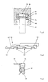
- the feed block 70 shown as a simple plate in FIG. 8 is designed for a plug-in base with four busbars and two auxiliary rails on which it can be placed, if necessary with the aid of snap-in means.
- the feed terminals 72 which differ only in terms of their size, are shown in more detail in FIG. 9.
- the U-shaped housing 74 is - in Fig. 8 clearly visible - completely open on two sides. Openings 78 are recessed in the two legs 76. The conductor can be fed from four directions.
- the legs 76 of the U-shaped housing continue on one side in the form of clamping claws 80.
- An axis 82 is arranged in the upper region of the clamping claws 80, about which an angled lever formed from a support plate 84 and a clamping claw 86 can be pivoted. If a connecting conductor is clamped by turning the screw 88 or by means of the plate 90 fastened to it, the connecting conductor presses on the supporting plate 84. The claw 86 simultaneously presses against the busbar by the lever action. A spring 87 exerts a force sufficient for positioning on the busbar when the feed clamp 72 is placed on it.
- the input terminal 24, which is not shown in detail in FIG. 1, can be designed as shown in this figure, and the electrical current can be supplied or removed at least partially via a conductor 23.
Landscapes
- Engineering & Computer Science (AREA)
- Power Engineering (AREA)
- Connector Housings Or Holding Contact Members (AREA)
- Emergency Protection Circuit Devices (AREA)
- Amplifiers (AREA)
- Electrical Discharge Machining, Electrochemical Machining, And Combined Machining (AREA)
- Ignition Installations For Internal Combustion Engines (AREA)
- Installation Of Bus-Bars (AREA)
Abstract
Description
Die vorliegende Erfindung betrifft eine Niederspannungsverteilung mit wenigstens an einer Stromschiene lösbar angeschlossenen Installationseinbaugeräten (im folgenden IEG genannt), einem Sammelschienensystem und Mitteln zur Einspeisung der Sammelschienen.The present invention relates to a low-voltage distribution with installation built-in devices (hereinafter referred to as IEG) detachably connected to at least one busbar, a busbar system and means for feeding the busbars.
Niederspannungsschaltgeräte, zu welchen insbesondere die IEG gehören, werden vor allem bei Nennströmen bis zu 63 A in grossen Mengen in Verteilungen eingesetzt. Die IEG umfassen beispielsweise Sicherungen, Leitungsschutzschalter, Fehlerstromschutzschalter, Motorschutzschalter, Hauptschalter, weitere Reiheneinbaugeräte und Schütze. Die IEG, welche einzeln oder zu mehreren Geräten zusammengefasst montiert werden, übernehmen das Schalten und/oder den Schutz der abgehenden Leitungen und damit der daran angeschlossenen Verbraucher.Low-voltage switchgear, which includes the IEG in particular, is used in large quantities in distributions, especially for rated currents up to 63 A. The IEG includes, for example, fuses, miniature circuit breakers, residual current circuit breakers, motor circuit breakers, main switches, other modular devices and contactors. The IEG, which are assembled individually or combined into several devices, take over the switching and / or protection of the outgoing lines and thus the consumers connected to them.
Es ist dabei üblich, von einem vorgeschalteten Ueberstromschutzorgan mit z.B. 100 oder 200 A Nennstrom eine grössere Anzahl von IEG mit elektrischer Energie zu versorgen.It is common to use an upstream overcurrent protection device with e.g. 100 or 200 A nominal current to supply a larger number of IEGs with electrical energy.
Bei bekannten Niederspannungsverteilungen werden nach einer ersten bekannten Variante die IEG auf einer Hutschiene montiert und mittels eines elektrischen Leiters je ein Pol eines IEG mit einer zu dieser parallel verlaufenden Sammelschiene verbunden. Nach einer zweiten bekannten, insbesondere in den USA üblichen Variante sind die IEG an Stelle einer Eingangsklemme mit einem Steckkontakt ausgerüstet. Damit ist es möglich, die Einspeisung über entsprechend ausgebildete und vorgefertigte Sammelschienen durch Aufstecken der IEG auf die Sammelschiene zu bewerkstelligen, wobei jedoch die IEG und die Sammelschienen zusammenpassend ausgebildet sein müssen.In known low-voltage distributions, according to a first known variant, the IEG are mounted on a top-hat rail and one pole of an IEG is connected to a busbar running parallel to this by means of an electrical conductor. According to a second known variant, which is particularly common in the USA, the IEGs are equipped with a plug contact instead of an input terminal. This makes it possible to carry out the feed via suitably designed and prefabricated busbars by plugging the IEG onto the busbar, but the IEG and the busbars must be designed to match.
Die von amerikanischen Herstellern geschaffenen Anschlusssysteme sind auf die entsprechenden Bedürfnisse konzipiert. Eine Kombination einzelner IEG mit solchen eines andern Herstellers ist nicht möglich. In Europa dagegen sind Abmessungen und Befestigungen der IEG schon sehr früh normiert worden. Für die Befestigung der IEG mit einem Schnappmechanismus dienen normierte Hutschienen von 35 mm Breite. Der schweizerische elektrotechnische Verein beispielsweise hat die europäische Norm für 35 mm breite Hutschienen zur Schnappbefestigung von IEG in der Norm SEV-EN 50 022 (1978) festgelegt. Die Hüllmasse der IEG, d.h. die Aussenmasse von deren Gehäuse, sind in DIN 43 880 festgelegt.The connection systems created by American manufacturers are designed for the corresponding needs. A combination of individual IEGs with those of another manufacturer is not possible. In Europe, on the other hand, IEG dimensions and fastenings were standardized very early on. Standardized 35 mm wide top-hat rails are used to attach the IEG with a snap mechanism. The Swiss electrotechnical association, for example, has specified the European standard for 35 mm wide top-hat rails for snap mounting of IEG in the standard SEV-EN 50 022 (1978). The envelope mass of the IEG, i.e. the external dimensions of their housings are specified in DIN 43 880.
Ausgehend von dieser Sachlage ist es in Europa üblich, die auf den Hutschienen befestigten IEG über eine Eingangsklemme an den Sammelschienen anzuschliessen. Zu diesem Zweck sind von den meisten Herstellern vorkonfektionierte Sammelschienen erhältlich; sie sind als Kamm ausgebildet und in einem Kunststoffprofil verankert. Dabei ist bei dreiphasigen Sammelschienen eine feste Phasenfolge vorgegeben. Falls Sammelschienen mit grösserem Querschnitt erforderlich sind, bieten die Hersteller üblicherweise Sammelschienenbügel an. Diese dienen zum Anschluss der einzelnen IEG an Sammelschienen unterschiedlichen Querschnitts. Mit Hilfe der Sammelschienenbügel lassen sich individuell gestaltete Einspeisungen der IEG vornehmen. Allen bekannten Lösungen haftet jedoch der Nachteil einer zeitraubenden und aufwendigen Montage an. Beim Aufbau einer Niederspannungsverteilung muss eine grosse Anzahl von Anschlusschrauben festgezogen werden. Weiter muss der Gewährleistung eines hinreichenden Abstandes zwischen Anschlüssen unterschiedlichen Potentials grosse Aufmerksamkeit geschenkt werden.Based on this situation, it is common in Europe to connect the IEGs mounted on the top-hat rails to the busbars using an input terminal. For this purpose, pre-assembled busbars are available from most manufacturers; they are designed as a comb and anchored in a plastic profile. A fixed phase sequence is specified for three-phase busbars. If busbars with a larger cross section are required, the manufacturers usually offer busbar brackets. These are used to connect the individual IEGs to busbars with different cross-sections. With the help of the busbar bracket, individually designed IEG feeds can be carried out. However, all known solutions have the disadvantage of time-consuming and complex assembly. When setting up a low-voltage distribution, a large number of connection screws must be tightened. Furthermore, great care must be taken to ensure that there is a sufficient distance between connections with different potentials.
Eine weitere Einschränkung durch die beschriebene Aufbauart besteht darin, dass es nicht auf einfache Weise möglich ist, einzelne IEG aus dem Verband auszubauen. Die zum Wegschnappen der IEG von der Hutschiene erforderliche Drehbewegung wird durch den in die Eingangsklemme hereinragenden Sammelschienenanschluss verunmöglicht. Das Auswechseln von IEG muss nicht nur bei verhältnismässig selten auftretenden Defekten erfolgen, sondern insbesondere auch, wenn beispielsweise in einer Maschinenhalle während der Bauphase bis zur Inbetriebnahme einzelne Verbraucher umgestellt werden und deshalb Nennstromanpassungen in der Niederspannungsverteilung notwendig sind.Another limitation of the type of construction described is that it is not easily possible is to expand individual IEG from the association. The rotary movement required to snap the IEG away from the top-hat rail is made impossible by the busbar connection protruding into the input terminal. The replacement of IEG not only has to take place in the case of relatively rare defects, but also in particular if, for example, individual consumers are changed in a machine hall during the construction phase up to commissioning and therefore nominal current adjustments in the low-voltage distribution are necessary.
Nach einer in der DE-OS 27 55 062 beschriebenen Ausführungsform einer Niederspannungsverteilung ist die Eingangsklemme der IEG als flexible Verbindung mit Schraubenanschluss passend auf entsprechend vorkonfektionierte Sammelschienen ausgebildet. Die Einspeisung kann dreiphasig erfolgen, wobei jedoch die Phasenfolge fest vorgegeben ist. In den beschriebenen Ausführungsformen ist der Neutralleiter nicht in das Sammelschienensystem miteinbezogen.According to an embodiment of a low-voltage distribution described in DE-OS 27 55 062, the input terminal of the IEG is designed as a flexible connection with a screw connection to suitably pre-assembled busbars. The feed can be three-phase, but the phase sequence is fixed. In the described embodiments, the neutral conductor is not included in the busbar system.
In der DE-OS 28 43 858 wird ein Sammelschienensystem zum Anschliessen von IEG beschrieben, das die Behebung einiger der oben beschriebenen Mängel erlaubt. Es muss jedoch eine grosse Zahl von Einzelteilen eingesetzt werden, welche für den Aufbau beschafft und montiert werden müssen.In DE-OS 28 43 858 a busbar system for connecting IEG is described, which allows the elimination of some of the shortcomings described above. However, a large number of individual parts must be used, which must be procured and assembled for the assembly.
Die Erfinder haben sich die Aufgabe gestellt, eine Niederspannungsverteilung der eingangs beschriebenen Art zu schaffen, die einfach in der Montage, kostensparend in der Beschaffung von zusätzlich notwendigen Einzelteilen und flexibel in der Verwendung ist sowie eine Lagerbewirtschaftung auf niedriger Investitionsstufe erlaubt.The inventors have set themselves the task of creating a low-voltage distribution of the type described at the outset, which is simple to assemble, saves costs in the procurement of additionally required individual parts and is flexible in use, and allows warehouse management at a low investment level.
Die Aufgabe wird erfindungsgemäss dadurch gelöst, dass
- die IEG im Bereich ihrer Gehäuserückseite pro Pol mit einem selbstfedernden Steckkontaktteil ausgerüstet sind, welches in einem in Längsrichtung des IEG verlaufenden Führungskanal schwimmend positionierbar ist, und von einer Sammelschiene - unter Bildung einer kontaktschlüssigen Verbindung - den elektrischen Strom abnimmt und in das IEG leitet bzw. bei einer Einspeisung über das IEG den elektrischen Strom der Sammelschiene zuführt,
- ein nach wenigstens einer Seite offener, aus elektrisch isolierendem Material bestehender Stecksockel, welcher die Sammelschienen haltert, auf einer Unterlage befestigbar ist und im wesentlichen aus in Längs- und Querrichtung verlaufenden Rippen besteht, wobei die in Abständen entsprechend der Normmasse der IEG verlaufenden Querrippen die Sammelschienen in ausgesparten Nuten aufnehmen, und
- die Mittel zur Einspeisung der Sammelschienen an frei wählbarer Stelle angeschlossen sind.According to the invention, the object is achieved in that
- The IEG in the area of its rear side of the housing is equipped with a self-resilient plug-in contact part, which can be positioned in a floating manner in a guide channel running in the longitudinal direction of the IEG, and takes the electrical current from a busbar - forming a contact connection - and conducts it into the IEG . supplies the electrical current to the busbar when it is fed in via the IEG,
- A plug base which is open on at least one side and consists of electrically insulating material and which holds the busbars, can be fastened to a base and essentially consists of ribs running in the longitudinal and transverse directions, the transverse ribs running at intervals in accordance with the standard dimensions of the IEG Pick up busbars in recessed grooves, and
- The means for feeding the busbars are connected at a freely selectable point.
Mit der erfindungsgemässen Lösung muss pro IEG-Typ (z.B. Leitungsschutzschalter, Fehlerstromschutzschalter) nur eine Bauform hergestellt werden. Die Lage des Steckkontaktteils kann durch entsprechende Positionierung an die Lage der Sammelschienen angepasst werden. Weil das Steckkontaktteil schwimmend positionierbar ist, kann es durch Temperaturschwankungen hervorgerufene Dilatationen bzw. Kontraktionen auffangen.With the solution according to the invention, only one design has to be produced for each IEG type (e.g. line circuit breaker, residual current circuit breaker). The position of the plug contact part can be adapted to the position of the busbars by appropriate positioning. Because the plug contact part can be positioned in a floating manner, it can absorb dilations or contractions caused by temperature fluctuations.
Die auf der Gehäuserückseite des IEG angeordnete Führung für das Steckkontaktteil umfasst alle dem Mechaniker bekannten Lösungen mit Arretiermöglichkeit. Zweckmässig wird ein auf einer Seite offener Führungskanal mit vertikalen Seitenwänden ausgespart. Im gleichen Abstand, parallel zur Auflagefläche auf dem Stecksockel, verlaufen in den Seitenwänden des Führungskanals auf derselben Seite des IEG offene Führungsnuten, in welche das/die Führungsplättchen eines Steckkontaktteils, welches seitlich eingeführt wird, eingreift/eingreifen. Weiter ist/sind im Führungskanal bzw. in den Führungsnuten an sich bekannte Vorrichtung/en angeordnet, die der schwimmenden Arretierung des Steckkontaktteils dienen. Die schwimmende Positionierung kann beispielsweise dadurch erzeugt werden, dass das in die Nuten eingeführte Plättchen des Steckkontaktteils von geringerer Dicke ist als die Breite der Nut.The guide for the plug-in contact part arranged on the back of the IEG housing includes all solutions known to the mechanic with locking options. A guide channel with vertical side walls that is open on one side is expediently left open. At the same distance, parallel to Contact surface on the plug-in base, open guide grooves run in the side walls of the guide channel on the same side of the IEG, into which the guide plate (s) of a plug-in contact part, which is inserted laterally, engage / engage. Furthermore, known device (s) are / are arranged in the guide channel or in the guide grooves, which serve for the floating locking of the plug contact part. The floating positioning can be generated, for example, in that the plate of the plug-in contact part inserted into the grooves is of a smaller thickness than the width of the groove.
In der Praxis ist das Steckkontaktteil zweckdienlich als sog. Stecktulpe ausgebildet, wobei die Form der beiden bevorzugt selbstfedernden Schenkel der geometrischen Form des Sammelschienenquerschnitts angepasst ist. Dieser kann jede zweckdienliche Form annehmen, vorzugsweise ist er jedoch rechteckig, quadratisch oder rund ausgebildet. Wie die Sammelschienen selbst bestehen die Stecktulpen aus elektrisch gut leitendem Material, beispielsweise aus Kupfer, Messing oder Aluminium.In practice, the plug contact part is expediently designed as a so-called plug tulip, the shape of the two preferably self-resilient legs being adapted to the geometric shape of the busbar cross section. This can take any convenient shape, but is preferably rectangular, square or round. Like the busbars themselves, the plug-in tulips are made of a material with good electrical conductivity, such as copper, brass or aluminum.
Der Stecksockel mit den eingefügten Sammelschienen besteht vorzugsweise aus einem gut spritzbaren Kunststoff, insbesondere einem Polyamid, Polyäthylen oder Polypropylen. Dieser Stecksockel hat bevorzugt einen modulartigen Aufbau, in dem Längs- und Querrippen in regelmässigen Abständen angeordnet sind. Zwischen den Querrippen können die Steckkontaktteile auf die Sammelschienen geklemmt werden.The plug-in base with the inserted busbars preferably consists of an easily sprayable plastic, in particular a polyamide, polyethylene or polypropylene. This plug-in base preferably has a modular structure in which the longitudinal and transverse ribs are arranged at regular intervals. The plug contact parts can be clamped onto the busbars between the cross ribs.
Obwohl die IEG dank des kraftschlüssigen Eingriffs fixiert sind, ist es vorteilhaft, sowohl an diesen als auch am Stecksockel Einschnappvorrichtungen bekannter Bauart anzuordnen. So kann die eine Längsseite des Stecksockels mit Widerlagern ausgerüstet sein, welche zu Beginn des Aufstekkens des IEG in eine entspechend ausgeformte Nut, welche im Bereich der IEG-Gehäuserückseite aus der vom Führungskanal abgewandten Schmalseite ausgespart ist, eingeführt werden. Ebenfalls auf der Gehäuserückseite, anschliessend an den offenen Führungskanal, können bei den IEG zwei vorspringende Nasen angeordnet sein. Die zweite Längsseite des Stecksockels ist in diesem Fall mit angeformten oder daran befestigten Schnapphaken versehen, welche mit den vorspringenden Nasen verrasten. Der Abstand der Schnapphaken entspricht beispielsweise dem Raster der Querrippen. Zweckmässig haben die Schnapphaken einen um eine Achse schwenkbaren, abgewinkelten Hebel, mit welchem die eingerasteten Nasen der Schnapphaken abgehoben werden können.Although the IEG are fixed thanks to the non-positive engagement, it is advantageous to arrange snap-in devices of known design on both these and on the plug-in base. For example, one long side of the plug-in base can be equipped with abutments, which at the start of plugging the IEG into a correspondingly shaped groove, which in the area of the IEG housing rear side from that of the guide channel recessed opposite narrow side is introduced. Likewise on the back of the housing, following the open guide channel, two protruding lugs can be arranged on the IEG. In this case, the second long side of the plug-in base is provided with snap hooks which are formed on or attached to it and which engage with the projecting lugs. The distance between the snap hooks corresponds, for example, to the grid of the transverse ribs. The snap hooks expediently have an angled lever which can be pivoted about an axis and with which the latched lugs of the snap hooks can be lifted off.
Auf der den allfällig angebrachten Schnapphaken gegenüberliegenden äusseren Längsseite des Stecksockels können offene, vertikale T- oder Schwalbenschwanzführungen angeformt sein, in welche von oben wenigstens ein Zusatzsockel eingeführt werden kann, welche/r der Aufnahme von weiteren Sammelschienen dient/en. Der Stecksockel kann also nach freiem Ermessen erweitert werden. So können beispielsweise ein Neutralleiter, ein PE-Leiter (Protective Earth) und/oder ein PEN-Leiter (Protective Earth + Neutral) auf einem Zusatzsockel angeordnet werden.Open, vertical T or dovetail guides can be formed on the outer long side of the plug-in base, which is opposite the snap hooks, in which at least one additional base can be inserted, which serves to accommodate additional busbars. The socket can therefore be expanded at your own discretion. For example, a neutral conductor, a PE conductor (Protective Earth) and / or a PEN conductor (Protective Earth + Neutral) can be arranged on an additional base.
Eine wahlweise aufgebrachte, sich über die ganze Länge des Stecksockels erstreckende, nach vorne orientierte Leiste ist zur Aufnahme von Beschriftungen bestimmt. In diesem Fall werden gleichzeitig das IEG auf der Gehäusevorderseite und die erwähnte Leiste beschriftet. Dadurch ist gewährleistet, dass beim Entfernen eines IEG die betreffende Stelle markiert ist, und das Gerät problemlos an derselben Stelle wieder eingesetzt werden kann.An optionally applied, forward-facing bar that extends over the entire length of the plug-in base is intended to accommodate lettering. In this case, the IEG on the front of the housing and the bar mentioned are labeled at the same time. This ensures that when an IEG is removed, the relevant location is marked and the device can be used again in the same location without any problems.
Der Stecksockel mit seinen Zusatzbestandteilen und den Sammelschienen ist also ein Elementebausatz, der nach Bedarf zusammengefügt wird.The plug-in base with its additional components and the busbars is therefore an element kit that can be assembled as required.
Die Stromzufuhr zu den Sammelschienen kann auf verschiedenste Weise erfolgen:
- Es werden separate Einspeiseklemmen verwendet, die an einem Ende der Sammelschienen, jedoch auch an geeigneter Stelle im Innern des Stecksockels, angeordnet sind.
- Ein Einspeiseblock, der vorzugsweise aus dem gleichen Material wie der Stecksockel besteht und nach dem gleichen Prinzip aufgebaut ist, wird verwendet. Dieser Einspeiseblock kann ggf. wie die IEG aufgeschnappt werden, er kann also ohne Werkzeuge an beliebiger Stelle im Stecksockel montiert und wieder entfernt werden. Der Einspeiseblock enthält eine der Anzahl Schienen entsprechende Anzahl von Einspeiseklemmen, wobei deren Pratzen in kontaktschlüssigem Eingriff mit den Sammelschienen stehen.
- Ein oder mehrere normal ausgebildete IEG können Strom über je einen Pol mittels eines Steckkontaktteils in eine Sammelschiene/Sammelschienen einspeisen, ohne dass die Grundfunktion des/der IEG beeinträchtigt wird.Power can be supplied to the busbars in a variety of ways:
- Separate supply terminals are used, which are arranged at one end of the busbars, but also at a suitable location inside the socket.
- An infeed block, which preferably consists of the same material as the plug-in base and is constructed on the same principle, is used. This feed block can be snapped on like the IEG, so it can be installed and removed anywhere in the socket without tools. The feeder block contains a number of feeder terminals corresponding to the number of rails, the claws of which are in contact with the busbars.
- One or more normally designed IEGs can feed current via one pole each into a busbar / busbars by means of a plug-in contact part, without the basic function of the IEG being impaired.
In allen Ausführungsformen der Einspeisung ist eine besondere Einspeiseklemme gut geeignet. Diese besteht aus einem U-förmig ausgebildeten Gehäuse mit von einer Schraube durchgriffener Basisfläche. Aus beiden Schenkeln des U-förmigen Gehäuses ist bevorzugt je eine grosse Oeffnung ausgestanzt. Damit kann der Anschlussleiter aus vier Richtungen in die Einspeiseklemme eingeführt und mit der Schraube, die stirnseitig auf ein Auflageplättchen einwirkt, festgeklemmt werden. Die Schenkel des U-förmigen Gehäuses setzen sich als Klemmpratzen fort. Beim Uebergang der Gehäuseschenkel in die Klemmpratzen ist eine Achse angeordnet, auf welcher ein abgewinkelter Hebel schwenkbar ist. Diesen Hebel bildet einerseits die entgegengesetzte Klemmpratze und andererseits das Auflageplättchen, auf welchem der Anschlussleiter aufliegt. Wird nun die Schraube angezogen, so wird dank der Wirkung des abgewinkelten Hebels nicht nur der Anschlussleiter festgeklemmt, sondern auch die beidseits der Sammelschiene angelegten Klemmpratzen zusammengedrückt. Somit kann mit dem Anziehen einer Schraube sowohl der Anschlussleiter fixiert als auch die Einspeiseklemme auf einer Sammelschiene kontaktschlüssig befestigt werden. Zur Positionierung der Einspeiseklemme auf einer Sammelschiene kann eine Federkraft auf die Klemmpratzen einwirken.A special feed terminal is well suited in all embodiments of the feed. This consists of a U-shaped housing with a base through which a screw passes. A large opening is preferably punched out from each of the two legs of the U-shaped housing. This allows the connecting conductor to be inserted into the feed terminal from four directions and clamped in place with the screw that acts on a support plate on the end. The legs of the U-shaped housing continue as clamping claws. At the transition of the housing legs into the clamping claws, an axis is arranged on which an angled lever can be pivoted. This lever forms on the one hand the opposite clamping claw and on the other hand the support plate on which the connection conductor rests. If the screw is tightened now, thanks to the Effect of the angled lever not only clamps the connecting conductor, but also compresses the clamps on both sides of the busbar. Thus, by tightening a screw, both the connection conductor can be fixed and the feed terminal can be fixed on a busbar in a contact-locking manner. A spring force can act on the clamps to position the feed terminal on a busbar.
Mit der erfindungsgemässen Lösung werden folgende Vorteile erzielt:
- Die IEG können ohne Werkzeuge, nur durch Aufstecken, montiert werden. Sie rasten ein und können auch ohne Werkzeuge wieder entfernt werden.
- Die IEG sind bei einem Umrüsten der Verbraucher leicht auswechelbar.
- Die Sammelschienensysteme, d.h. die Stecksockel mit den Sammelschienen, sind nach dem Baukastenprinzip zusammenschnappbar. Ebenfalls nach dem Baukastenprinzip können Zusatzsockel angefügt werden.
- Pro IEG-Typ muss nur eine Variante - und nicht mehrere mit Steckkontaktteilen in verschiedenen Positionen - hergestellt und an Lager gehalten werden.The following advantages are achieved with the solution according to the invention:
- The IEG can be installed without tools, just by plugging it on. They snap into place and can be removed without tools.
- The IEG can be easily replaced when converting the consumer.
- The busbar systems, ie the plug-in base with the busbars, can be snapped together using the modular principle. Additional bases can also be added using the modular principle.
- Only one variant per IEG type - and not several with plug-in contact parts in different positions - has to be manufactured and kept in stock.
Durch das Aufbringen der IEG werden die stromführenden Sammelschienen automatisch nach vorne abgedeckt und einer Berührungsgefahr entzogen.By attaching the IEG, the live busbars are automatically covered to the front and removed from the risk of contact.
Die IEG gemäss vorliegender Erfindung können auch für konventionelle Niederspannungsverteilungen verwendet werden, indem die für Hutschienen notwendige Aussparung angebracht ist. In die üblicherweise für ein Steckkontaktteil vorgesehenen Nuten wird eine Klemm- oder Feststellbride einge setzt, welche in die Hutschiene einschnappen kann. Allerdings muss ein solches IEG noch eine Eingangsklemme haben. Bei polyvalenter Verwendung des IEG ist dieses mit einer Eingangsklemme ausgerüstet, die entweder über einen flexiblen Leiter mit dem Steckkontaktteil verbunden oder an welchem - bei fehlendem Steckkontaktteil - der Verbindungsleiter zur Sammelschiene bzw. der Anschlussdraht festgeklemmt ist.The IEG according to the present invention can also be used for conventional low-voltage distributions by providing the cutout required for top-hat rails. A clamp or locking clamp is inserted into the grooves usually provided for a plug contact part sets, which can snap into the top-hat rail. However, such an IEG must still have an input terminal. If the IEG is used polyvalently, it is equipped with an input terminal which is either connected to the plug contact part via a flexible conductor or to which - in the absence of a plug contact part - the connecting conductor to the busbar or the connecting wire is clamped.
Bei dieser Ausführungsform, mit Eingangsklemme und Positionierungseinrichtungen für ein Steckkontaktteil bzw. eine Klemm- oder Feststellbride, ist es möglich, IEG ohne die erwähnten Teile zu montieren oder an Lager zu legen. Je nach Kundenwunsch kann, unmittelbar vor der Auslieferung oder sogar erst durch den Anwender selbst, das Steckkontaktteil oder die Klemm- bzw. Feststellbride eingesetzt werden.In this embodiment, with input terminal and positioning devices for a plug contact part or a clamping or locking bracket, it is possible to assemble IEG without the mentioned parts or to store them. Depending on the customer's requirements, the plug-in contact part or the clamping or locking clamp can be used immediately before delivery or even only by the user himself.
Die Erfindung wird anhand der nachfolgenden Ausführungsbeispiele näher erläutert. Es zeigen schematisch:
- - Fig. 1 eine teilweise aufgeschnittene Ansicht eines IEG mit eingebauter Stecktulpe,
- - Fig. 2 einen vertikalen Querschnitt A - A (Fig. 1) durch den Führungskanal eines IEG,
- - Fig. 3 eine perspektivische Ansicht eines Arretierschiebers,
- - Fig. 4 eine perspektivische Ansicht einer Stecktulpe,
- - Fig. 5 einen Vertikalschnitt B - B (Fig. 7) durch einen Stecksockel,
- - Fig. 6 einen Vertikalschnitt durch einen Zusatzsockel,
- - Fig. 7 eine Draufsicht auf einen Stecksockel,
- - Fig. 8 eine perspektivische Darstellung eines Einspeiseblocks mit vier Haupt- und zwei Hilfseinspeiseklemmen,
- - Fig. 9 eine perspektivische Ansicht einer Einspeiseklemme, und
- - Fig. 10 eine teilweise aufgeschnittene Ansicht eines auf Hutschienen montierbaren IEG.
- 1 is a partially cut-away view of an IEG with built-in plug tulip,
- 2 shows a vertical cross section A - A (FIG. 1) through the guide channel of an IEG,
- 3 shows a perspective view of a locking slide,
- 4 shows a perspective view of a plug tulip,
- 5 shows a vertical section BB (FIG. 7) through a plug-in base,
- 6 shows a vertical section through an additional base,
- 7 is a plan view of a plug-in base,
- 8 is a perspective view of a feed block with four main and two auxiliary feed terminals,
- 9 is a perspective view of a feed clamp, and
- 10 is a partially cut-away view of an IEG that can be mounted on top-hat rails.
Das in Fig. 1 dargestellte IEG 10 ist von einem Gehäuse 12 mit normierten Aussenmassen umgeben. An der Vorderseite des IEG ist ein Schalthebel 14 sichtbar. Auf der Rückseite des Gehäuses ist eine auf der linken Seite schwalbenschwanzförmige Aussparung 16 zum Aufschnappen auf eine nicht dargestellte Hutschiene sichtbar. Die Aussparung 16 hat jedoch beim IEG 10 gemäss Fig. 1 keine Funktion und wäre im Prinzip nicht notwendig.The
In Pos. I ist - in einem Führungskanal 18 schwimmend positioniert - eine Stecktulpe 20 angeordnet. Ueber einen flexiblen Leiter 22 ist die Stecktulpe mit einer wie bei konventionellen Ausführungsformen gestalteten, den Strom einspeisenden Eingangsklemme 24 verbunden. Von dort wird der Strom in das Innere des IEG geleitet. Nach einer nicht dargestellten Variante kann das Gehäuse 12 am Ort der gezeichneten Eingangsklemme 24 geschlossen sein. Der elektrische Strom wird in diesem Fall von der Stecktulpe 20 direkt in das Innere des IEG geführt.In position I - positioned floating in a guide channel 18 - a plug-in
Mit II und III sind weitere mögliche Positionen der Stecktulpe 20 angedeutet, je nach der Lage der einspeisenden Sammelschiene.With II and III further possible positions of the
Zur stabileren Fixierung des aufgesteckten IEG ist, auf der einen Seite abkragend, eine Nase 26, auf der andern Seite eine Nut 28 angeordnet.For a more stable fixation of the plugged-on IEG, a
Der Führungskanal 18 für die Stecktulpe 20 ist in Fig. 2 im Detail dargestellt. In den Seitenwänden 30 des Führungskanals sind zwei parallel verlaufende Führungsnuten 32 ersichtlich, in welchen das im vorliegenden Fall mit der Stecktulpe 20 einstückig ausgebildete Führungsplättchen 34 mit dem Arretierschieber 36 eingeführt wird. Dieser Arretierschieber ist in Fig. 3 detailliert dargestellt, er besteht aus einem elastischen Kunststoff, beispielsweise Polyäthylen, und hat im vorliegenden Fall auf seinen beiden Schenkeln 38 je drei Einkerbungen 40, welche in Breite und Tiefe etwa den Dimensionen des Führungsplättchens 34 der Stecktulpe 20 entsprechen. Am Verbindungsstück 42 der beiden Schenkel 38 ist ein Arretierhaken 44 angeformt.The
Die beiden verhältnismässig dünnen Führungsflansche 46 (Fig. 2) sind ebenfalls an je drei Stellen, entsprechend den Dimensionen der Einkerbungen 40 des Arretierschiebers 36 ausgespart. Ist der Arretierschieber derart positioniert, dass die Einkerbungen 40 unter den Aussparungen in den Führungsflanschen 46 liegen, können Führungsplättchen 34 der Stecktulpe 20 von vorne in die Einkerbungen 40 des Arretierschiebers eingeführt werden. Wird der Arretierschieber in Längsrichtung des Führungskanals 18 verschoben, so werden die Führungsplättchen 34 und damit die Stecktulpe 20 selbst durch den Arretierschieber 36 und die Führungsflansche 46 fixiert. Das das Plättchen 34 jedoch etwas Spiel hat, ist die Stecktulpe 20 schwimmend arretiert. Der Arretierhaken 44 des Arretierschiebers 36 kann durch Einstecken in ein entsprechend ausgespartes Loch arretiert werden.The two relatively thin guide flanges 46 (FIG. 2) are also cut out at three locations, corresponding to the dimensions of the
Die in Fig. 4 dargestellte Stecktulpe 20 ist die in der Praxis üblicherweise angewandte Form des selbstfedernden Steckkontaktteils. Die Funktion des mit der Feder einstückig ausgebildeten Führungsplättchens 34 ist in der Beschreibung von Fig. 2 und 3 diskutiert worden. Am Führungsplättchen 34 elektrisch leitend verbunden ist ein in das Innere des IEG führender flexibler Leiter 22. Die Klemmkraft der Stecktulpe 20 wird bedeutend erhöht, wenn ein Spannring 52 darüber angeordnet ist. Bei einer nicht selbstfedernden Stecktulpe 20 muss ein Spannring 52 angeordnet werden.The plug-in
Der in den Fig. 5 und 7 dargestellte Stecksockel 54 besteht im wesentlichen aus Längs- 56 und Querrippen 58. Die Sammelschienen, welche in entsprechend geformte Aussparungen der Querrippen 58 eingeschoben sind, umfassen die drei Pha sen L₁, L₂ und L₃, den Neutralleiter N, den Hilfskontaktleiter H und den Signalkontaktleiter S. In der gemäss Fig. 5 oberen Längsseitenwand 60 sind vorne offene, horizontale T-förmige Nuten 62 zur Aufnahme eine Zusatzsockels 64 ausgespart, was in Fig. 6 mit einem Pfeil 66 angedeutet ist. Der Zusatzsockel 64 enthält - ebenfalls in Ausformungen der Querstege 58 gehaltert - die Sammelschienen für die Erde PE und den Neutralleiter N.5 and 7 essentially consists of longitudinal 56 and
Die modulartig aufgebauten Stecksockel 54 bzw. Zusatzsockel 64 sind in Längsrichtung der Leiter zweckmässig sechs- oder achtteilig.The
Es können nicht nur von einem Stecksockel 54 Zusatzsockel 64 aufgenommen, sondern mehrere Stecksockel 54 können in Längsrichtung der Leiter in bekannter Weise aneinander gefügt werden. Das Aneinanderfügen einzelner Stecksockel erfolgt beispielsweise durch gegenseitig verbundene, an den Stirnseiten angebrachte bzw. angeformte Haken.It is not only possible to receive
Die an den Steckstockel 54 angeformten Schnapphaken 59 sind federnd ausgebildet und können mit den Nasen 26 der IEG 10 verrasten. Die an die andere Längsseite des Stecksockels 54 angeformten Widerlager 55 greifen in die Nut 28 der IEG ein.The snap hooks 59 formed on the
In den Fig. 5 und 7 ist eine Leiste 68 zum Beschriften dargestellt, wobei die Beschriftung derjenigen auf dem entsprechenden IEG entspricht.5 and 7, a
Der in Fig. 8 als einfache Platte dargestellte Einspeiseblock 70 ist für einen Stecksockel mit vier Sammelschienen und zwei Hilfsschienen konzipiert, auf welchen er aufgesetzt werden kann, ggf. mit Hilfe von Mitteln zum Einschnappen. Die lediglich in bezug auf die Grösse unterschiedlichen Einspeiseklemmen 72 sind in Fig. 9 näher dargestellt. Das U-förmig ausgebildete Gehäuse 74 ist - in Fig. 8 gut ersichtlich - auf zwei Seiten vollständig offen. In den beiden Schenkeln 76 sind Oeffnungen 78 ausgespart. So kann die Leiterzuführung aus vier Richtungen erfolgen. Die Schenkel 76 des U-förmigen Gehäuses setzen sich auf einer Seite in Form von Klemmpratzen 80 fort. Im oberen Bereich der Klemmpratzen 80 ist eine Achse 82 angeordnet, um welche ein aus einem Auflageplättchen 84 und einer Klemmpratze 86 gebildeter, abgewinkelter Hebel schwenkbar ist. Wird ein Anschlussleiter mittels Umdrehens der Schraube 88 bzw. mittels des daran befestigten Plättchens 90 festgeklemmt, so drückt der Anschlussleiter auf das Auflageplättchen 84. Durch die Hebelwirkung drückt die Klemmpratze 86 gleichzeitig gegen die Sammelschiene. Eine Feder 87 übt beim Aufsetzen der Einspeiseklemme 72 eine zur Positionierung auf der Sammelschiene hinreichende Kraft aus.The
Das in Fig. 10 dargestellte IEG 10 enthält keine positionierbare Stecktulpe. In Nuten 93 geführt ist eine gefederte Klemm- bzw. Feststellbride 92 angeordnet, welche unter der Bezeichnung RAFIX-Bride bekannt ist und das Aufschnappen des Geräts auf einer üblichen Hutschiene erlaubt. Der elektrische Strom wird über einen Leiter bekannter Ausführungsform der Eingangsklemme 24 zugeführt bzw. von ihr abgeführt. Diese besteht aus Schraube 94, Käfig 96 und Anschlussstück 98. Diese Ausführungsform zeigt, dass eine Variante des erfindungsgemässen IEG, mit einer Eingangsklemme 24, ohne erheblichen Aufwand in konventionellen Systemem mit Hutschienen einbaubar ist.The
Die in Fig. 1 nicht im Detail dargestellte Eingangsklemme 24 kann wie in dieser Figur gezeigt ausgebildet sein, und der elektrische Strom kann mindestens teilweise über einen Leiter 23 zugeführt bzw. abgeführt werden.The
Claims (10)
dadurch gekennzeichnet, das
- die IEG (10) im Bereich ihrer Gehäuserückseite pro Pol mit einem Steckkontaktteil (20) ausgerüstet sind, welches in einem in Längsrichtung des IEG (10) verlaufenden Führungskanal (18) schwimmend positionierbar ist, und von einer Sammelschiene - unter Bildung einer kontaktschlüssigen Verbindung - den elektrischen Strom abnimmt und in das IEG (10) leitet bzw. bei einer Einspeisung über das IEG den elektrischen Strom der Sammelschiene zuführt,
- ein nach wenigstens einer Seite offener, aus elektrisch isolierendem Material bestehender Stecksockel (54), welcher die Sammelschienen (L₁,L₂,L₃,N,H,S) haltert, auf einer Unterlage befestigbar ist und im wesentlichen aus in Längs- und Querrichtung verlaufenden Rippen (56,58) besteht, wobei die in Abständen entsprechend der Normmasse der IEG (10) verlaufenden Querrippen (58) die Sammelschienen in ausgesparten Nuten aufnehmen, und
- die Mittel zur Einspeisung der Sammelschienen an frei wählbarer Stelle angeschlossen sind.1. Low-voltage distribution with installation built-in devices (IEG) detachably connected to at least one busbar, a busbar system and means for feeding the busbars,
characterized in that
- The IEG (10) are equipped in the area of their rear side per pole with a plug-in contact part (20) which can be positioned in a floating manner in a guide channel (18) running in the longitudinal direction of the IEG (10), and from a busbar - with the formation of a contact-locking connection - the electrical current decreases and leads into the IEG (10) or, when it is fed in via the IEG, supplies the electrical current to the busbar,
- An open to at least one side, made of electrically insulating material plug-in base (54) which holds the busbars (L₁, L₂, L₃, N, H, S), can be fastened on a base and essentially from in the longitudinal and transverse directions extending ribs (56, 58), the transverse ribs (58) running at intervals corresponding to the standard dimensions of the IEG (10) receiving the busbars in recessed grooves, and
- The means for feeding the busbars are connected at a freely selectable point.
Priority Applications (1)
| Application Number | Priority Date | Filing Date | Title |
|---|---|---|---|
| AT86810538T ATE48926T1 (en) | 1985-12-14 | 1986-11-25 | LOW VOLTAGE DISTRIBUTION. |
Applications Claiming Priority (2)
| Application Number | Priority Date | Filing Date | Title |
|---|---|---|---|
| CH530985 | 1985-12-14 | ||
| CH5309/85 | 1985-12-14 |
Publications (2)
| Publication Number | Publication Date |
|---|---|
| EP0229590A1 true EP0229590A1 (en) | 1987-07-22 |
| EP0229590B1 EP0229590B1 (en) | 1989-12-20 |
Family
ID=4291429
Family Applications (1)
| Application Number | Title | Priority Date | Filing Date |
|---|---|---|---|
| EP86810538A Expired EP0229590B1 (en) | 1985-12-14 | 1986-11-25 | Low-voltage distribution |
Country Status (4)
| Country | Link |
|---|---|
| EP (1) | EP0229590B1 (en) |
| AT (1) | ATE48926T1 (en) |
| DE (1) | DE3667741D1 (en) |
| ES (1) | ES2013259B3 (en) |
Cited By (27)
| Publication number | Priority date | Publication date | Assignee | Title |
|---|---|---|---|---|
| EP0327385A1 (en) * | 1988-02-05 | 1989-08-09 | Delta Electrical (Holdings) Limited | A mounting assembly for electrical device |
| DE4021824A1 (en) * | 1990-07-09 | 1992-01-16 | Abb Patent Gmbh | DISTRIBUTION SYSTEM WITH ELECTRICAL INSTALLATION DEVICES IN NARROW CONSTRUCTION ON A CARRIER |
| DE4021826A1 (en) * | 1990-07-09 | 1992-01-16 | Abb Patent Gmbh | DISTRIBUTION SYSTEM WITH AT LEAST TWO ROWS OF ELECTRICAL INSTALLATION DEVICES IN NARROW CONSTRUCTION |
| FR2677779A1 (en) * | 1991-06-14 | 1992-12-18 | Telemecanique | INTERFACE DEVICE FOR A PROCESSING UNIT, ESPECIALLY AUTOMATED. |
| WO1993004514A1 (en) * | 1991-08-20 | 1993-03-04 | Crabtree Electrical Industries Limited | Improvements relating to the mounting of circuit breakers |
| DE4327715A1 (en) * | 1993-08-18 | 1995-02-23 | Abb Patent Gmbh | Device for supplying electrical energy to at least one electrical installation device |
| DE9418316U1 (en) * | 1994-11-15 | 1996-03-21 | Aeg Niederspannungstech Gmbh | Device for connecting electrical installation devices |
| DE19511284C1 (en) * | 1995-03-28 | 1996-07-11 | Loh Kg Rittal Werk | Equipment adaptor for current rails of bus=bar system |
| EP0748013A1 (en) * | 1995-06-07 | 1996-12-11 | Schneider Electric Sa | Device for electrical connection of modular apparatus such as switches or the like |
| DE19530659C1 (en) * | 1995-08-21 | 1997-02-20 | Weber Ag | Low voltage busbar system |
| EP0660444B1 (en) * | 1993-12-22 | 1998-10-21 | CMC Carl Maier + Cie AG | Low voltage distributor |
| DE19748429A1 (en) * | 1997-11-03 | 1999-05-06 | Siemens Ag | Switchgear unit capable of communication |
| EP1104047A2 (en) * | 1999-11-29 | 2001-05-30 | ABB CMC Carl Maier AG | Terminal structure for a low voltage distributor |
| FR2830677A1 (en) * | 2001-10-09 | 2003-04-11 | Schneider Electric Ind Sa | Motor load controlling electrical module having electrical connector bundles electrical control apparatus with rear section connection connecting fixing support power and base. |
| EP1331711A2 (en) * | 1990-08-21 | 2003-07-30 | Electrium Sales Limited | Electricity supply assembly |
| EP1351336A1 (en) * | 2002-03-11 | 2003-10-08 | ABB Schweiz AG | Connector module for plug-in installation system |
| DE19531366C2 (en) * | 1995-08-25 | 2003-11-27 | Weber Ag Emmenbruecke | Conductor connector for the continuous connection of at least one first conductor to a busbar |
| JP2007311370A (en) * | 2007-09-03 | 2007-11-29 | Matsushita Electric Works Ltd | Circuit breaker |
| WO2008131915A1 (en) * | 2007-04-28 | 2008-11-06 | Abb Ag | Installation switching device |
| EP2461440A2 (en) | 2010-12-03 | 2012-06-06 | ABB Schweiz AG | Plug-in system |
| DE202013003925U1 (en) | 2013-04-26 | 2013-06-17 | Abb Schweiz Ag | Additional socket and plug socket assembly manufacturable with it |
| GB2531823A (en) * | 2015-02-05 | 2016-05-04 | Symmetrical Power Ltd | Consumer units, receptacles for consumer units and consumer unit systems |
| DE202017104591U1 (en) * | 2017-08-01 | 2018-11-06 | Wago Verwaltungsgesellschaft Mbh | Base unit for DIN rail mounted device |
| EP2834892B1 (en) * | 2012-04-06 | 2021-01-06 | Labinal, LLC | Circuit breaker adaptor for plug-in circuit breaker panel |
| CN112821206A (en) * | 2021-02-07 | 2021-05-18 | 浙江世隆电气科技有限公司 | Novel closed bus structure of distribution electrical appliance |
| DE102020106085A1 (en) | 2020-03-06 | 2021-09-09 | Phoenix Contact Gmbh & Co. Kg | Connection device and electromechanical assembly |
| WO2022224201A1 (en) | 2021-04-22 | 2022-10-27 | Hager Industrie Ag | Socket system |
Citations (2)
| Publication number | Priority date | Publication date | Assignee | Title |
|---|---|---|---|---|
| DE1946714A1 (en) * | 1969-09-16 | 1971-03-25 | Friedel Goedde | Insulated busbars for three-phase connection of miniature circuit breakers using pluggable connection pieces |
| DE2030449A1 (en) * | 1970-06-20 | 1972-01-05 | Bbc Brown Boveri & Cie | Contact device for electrical installation equipment |
-
1986
- 1986-11-25 AT AT86810538T patent/ATE48926T1/en not_active IP Right Cessation
- 1986-11-25 EP EP86810538A patent/EP0229590B1/en not_active Expired
- 1986-11-25 ES ES86810538T patent/ES2013259B3/en not_active Expired - Lifetime
- 1986-11-25 DE DE8686810538T patent/DE3667741D1/en not_active Expired - Lifetime
Patent Citations (2)
| Publication number | Priority date | Publication date | Assignee | Title |
|---|---|---|---|---|
| DE1946714A1 (en) * | 1969-09-16 | 1971-03-25 | Friedel Goedde | Insulated busbars for three-phase connection of miniature circuit breakers using pluggable connection pieces |
| DE2030449A1 (en) * | 1970-06-20 | 1972-01-05 | Bbc Brown Boveri & Cie | Contact device for electrical installation equipment |
Cited By (45)
| Publication number | Priority date | Publication date | Assignee | Title |
|---|---|---|---|---|
| EP0327385A1 (en) * | 1988-02-05 | 1989-08-09 | Delta Electrical (Holdings) Limited | A mounting assembly for electrical device |
| DE4021824A1 (en) * | 1990-07-09 | 1992-01-16 | Abb Patent Gmbh | DISTRIBUTION SYSTEM WITH ELECTRICAL INSTALLATION DEVICES IN NARROW CONSTRUCTION ON A CARRIER |
| DE4021826A1 (en) * | 1990-07-09 | 1992-01-16 | Abb Patent Gmbh | DISTRIBUTION SYSTEM WITH AT LEAST TWO ROWS OF ELECTRICAL INSTALLATION DEVICES IN NARROW CONSTRUCTION |
| DE4021824C2 (en) * | 1990-07-09 | 2001-08-30 | Abb Patent Gmbh | Distribution system with electrical installation devices in narrow construction that can be lined up on a support element |
| DE4021826C2 (en) * | 1990-07-09 | 1999-07-29 | Abb Patent Gmbh | Distribution system with at least two rows of electrical installation devices arranged in a narrow manner |
| EP1331711A2 (en) * | 1990-08-21 | 2003-07-30 | Electrium Sales Limited | Electricity supply assembly |
| EP1331711A3 (en) * | 1990-08-21 | 2004-03-03 | Electrium Sales Limited | Electricity supply assembly |
| FR2677779A1 (en) * | 1991-06-14 | 1992-12-18 | Telemecanique | INTERFACE DEVICE FOR A PROCESSING UNIT, ESPECIALLY AUTOMATED. |
| WO1992022947A1 (en) * | 1991-06-14 | 1992-12-23 | Telemecanique S.A. | Interface device for processing unit, particularly a logic controller |
| WO1993004514A1 (en) * | 1991-08-20 | 1993-03-04 | Crabtree Electrical Industries Limited | Improvements relating to the mounting of circuit breakers |
| DE4327715A1 (en) * | 1993-08-18 | 1995-02-23 | Abb Patent Gmbh | Device for supplying electrical energy to at least one electrical installation device |
| EP0660444B1 (en) * | 1993-12-22 | 1998-10-21 | CMC Carl Maier + Cie AG | Low voltage distributor |
| DE9418316U1 (en) * | 1994-11-15 | 1996-03-21 | Aeg Niederspannungstech Gmbh | Device for connecting electrical installation devices |
| US5938461A (en) * | 1995-03-28 | 1999-08-17 | Rittal-Werk Rudolf Loh Gmbh & Co. Kg | Device adapter for busbar in a busbar system |
| DE19511284C1 (en) * | 1995-03-28 | 1996-07-11 | Loh Kg Rittal Werk | Equipment adaptor for current rails of bus=bar system |
| US5745338A (en) * | 1995-06-07 | 1998-04-28 | Schneider Electric S.A. | Device for assembly and electrical connection of modular apparatuses such as circuit breakers or similar |
| FR2735290A1 (en) * | 1995-06-07 | 1996-12-13 | Schneider Electric Sa | ASSEMBLY AND ELECTRICAL CONNECTION DEVICE FOR MODULAR APPLIANCES SUCH AS CIRCUIT BREAKERS OR SIMILAR |
| EP0748013A1 (en) * | 1995-06-07 | 1996-12-11 | Schneider Electric Sa | Device for electrical connection of modular apparatus such as switches or the like |
| EP0762583A2 (en) * | 1995-08-21 | 1997-03-12 | Weber Ag | Low voltage bus bar system |
| EP0762583A3 (en) * | 1995-08-21 | 1997-09-24 | Weber Ag | Low voltage bus bar system |
| DE19530659C1 (en) * | 1995-08-21 | 1997-02-20 | Weber Ag | Low voltage busbar system |
| DE19531366C2 (en) * | 1995-08-25 | 2003-11-27 | Weber Ag Emmenbruecke | Conductor connector for the continuous connection of at least one first conductor to a busbar |
| US6411500B1 (en) | 1997-11-03 | 2002-06-25 | Siemens Aktiengesellschaft | Communication switchgear unit with busbar assembly |
| DE19748429A1 (en) * | 1997-11-03 | 1999-05-06 | Siemens Ag | Switchgear unit capable of communication |
| DE19957277A1 (en) * | 1999-11-29 | 2001-05-31 | Abb Cmc Carl Maier Ag Schaffha | Terminal arrangement for a low-voltage distributor |
| EP1104047A2 (en) * | 1999-11-29 | 2001-05-30 | ABB CMC Carl Maier AG | Terminal structure for a low voltage distributor |
| EP1104047A3 (en) * | 1999-11-29 | 2003-04-02 | ABB Schweiz AG | Terminal structure for a low voltage distributor |
| FR2830677A1 (en) * | 2001-10-09 | 2003-04-11 | Schneider Electric Ind Sa | Motor load controlling electrical module having electrical connector bundles electrical control apparatus with rear section connection connecting fixing support power and base. |
| EP1351336A1 (en) * | 2002-03-11 | 2003-10-08 | ABB Schweiz AG | Connector module for plug-in installation system |
| WO2008131915A1 (en) * | 2007-04-28 | 2008-11-06 | Abb Ag | Installation switching device |
| JP2007311370A (en) * | 2007-09-03 | 2007-11-29 | Matsushita Electric Works Ltd | Circuit breaker |
| JP4665952B2 (en) * | 2007-09-03 | 2011-04-06 | パナソニック電工株式会社 | Circuit breaker |
| EP2461440A2 (en) | 2010-12-03 | 2012-06-06 | ABB Schweiz AG | Plug-in system |
| US8625257B2 (en) | 2010-12-03 | 2014-01-07 | Abb Schweiz Ag | Plug-in system |
| EP2834892B1 (en) * | 2012-04-06 | 2021-01-06 | Labinal, LLC | Circuit breaker adaptor for plug-in circuit breaker panel |
| DE202013003925U1 (en) | 2013-04-26 | 2013-06-17 | Abb Schweiz Ag | Additional socket and plug socket assembly manufacturable with it |
| GB2531843A (en) * | 2015-02-05 | 2016-05-04 | Symmetrical Power Ltd | Consumer units, receptacles for consumer units and consumer unit systems. |
| GB2531823B (en) * | 2015-02-05 | 2016-09-21 | Symmetrical Power Ltd | Consumer units, receptacles for consumer units and consumer unit systems |
| GB2531843B (en) * | 2015-02-05 | 2016-09-21 | Symmetrical Power Ltd | Consumer units, receptacles for consumer units and consumer unit systems. |
| GB2531823A (en) * | 2015-02-05 | 2016-05-04 | Symmetrical Power Ltd | Consumer units, receptacles for consumer units and consumer unit systems |
| DE202017104591U1 (en) * | 2017-08-01 | 2018-11-06 | Wago Verwaltungsgesellschaft Mbh | Base unit for DIN rail mounted device |
| DE102020106085A1 (en) | 2020-03-06 | 2021-09-09 | Phoenix Contact Gmbh & Co. Kg | Connection device and electromechanical assembly |
| CN112821206A (en) * | 2021-02-07 | 2021-05-18 | 浙江世隆电气科技有限公司 | Novel closed bus structure of distribution electrical appliance |
| WO2022224201A1 (en) | 2021-04-22 | 2022-10-27 | Hager Industrie Ag | Socket system |
| DE102021110327A1 (en) | 2021-04-22 | 2022-10-27 | Hager Industrie Ag | socket system |
Also Published As
| Publication number | Publication date |
|---|---|
| ATE48926T1 (en) | 1990-01-15 |
| EP0229590B1 (en) | 1989-12-20 |
| DE3667741D1 (en) | 1990-01-25 |
| ES2013259B3 (en) | 1990-05-01 |
Similar Documents
| Publication | Publication Date | Title |
|---|---|---|
| EP0229590B1 (en) | Low-voltage distribution | |
| DE102006022374B4 (en) | switchgear | |
| EP0592829B1 (en) | Overload relay to combine with contactors | |
| EP1600045B1 (en) | Frame comprising an electrifying device | |
| EP0170161B1 (en) | Installation apparatus for bus-bar systems | |
| DE69932764T2 (en) | Customizable outgoing module of a low-voltage switch cell | |
| EP0639877B1 (en) | Device for supplying at least one electric installation appliance with electric energy | |
| EP0270995B1 (en) | Appliance adapter | |
| EP0467171A2 (en) | Distribution installation with small size apparatuses mounted side by side on a supporting means | |
| DE1540378A1 (en) | Electric switchboard | |
| EP0053252B1 (en) | Adapter for electrical installation equipment | |
| DE2616525C2 (en) | Electrical installation distribution | |
| EP0454016A2 (en) | Mains clamp fixed on a standardized support rail | |
| EP0821454B1 (en) | Connecting device for electrical installation apparatus | |
| EP0017163B1 (en) | Cover for terminals of electrical switches | |
| DE19530659C1 (en) | Low voltage busbar system | |
| DE4021826A1 (en) | DISTRIBUTION SYSTEM WITH AT LEAST TWO ROWS OF ELECTRICAL INSTALLATION DEVICES IN NARROW CONSTRUCTION | |
| EP0262554B1 (en) | Device for the connection of installation apparatuses to the current bus-bars of a basic bus-bar system | |
| DE3709227C2 (en) | Distribution arrangement for electrical consumers | |
| DE19629318A1 (en) | Current distributor for several parallel loads in telecommunications equipment | |
| DE19748555C1 (en) | Electrical switch apparatus cabinet | |
| DE2733895C2 (en) | Installation device for inserting a module | |
| WO1996030982A1 (en) | Low-voltage switch system for supplying or distributing electric power | |
| DE10216371A1 (en) | auxiliary switch | |
| EP0857364B1 (en) | Power feed box |
Legal Events
| Date | Code | Title | Description |
|---|---|---|---|
| PUAI | Public reference made under article 153(3) epc to a published international application that has entered the european phase |
Free format text: ORIGINAL CODE: 0009012 |
|
| AK | Designated contracting states |
Kind code of ref document: A1 Designated state(s): AT BE CH DE ES FR GB IT LI NL SE |
|
| 17P | Request for examination filed |
Effective date: 19870630 |
|
| 17Q | First examination report despatched |
Effective date: 19890207 |
|
| GRAA | (expected) grant |
Free format text: ORIGINAL CODE: 0009210 |
|
| AK | Designated contracting states |
Kind code of ref document: B1 Designated state(s): AT BE CH DE ES FR GB IT LI NL SE |
|
| PG25 | Lapsed in a contracting state [announced via postgrant information from national office to epo] |
Ref country code: BE Effective date: 19891220 |
|
| REF | Corresponds to: |
Ref document number: 48926 Country of ref document: AT Date of ref document: 19900115 Kind code of ref document: T |
|
| REF | Corresponds to: |
Ref document number: 3667741 Country of ref document: DE Date of ref document: 19900125 |
|
| ITF | It: translation for a ep patent filed |
Owner name: DE DOMINICIS & MAYER S.R.L. |
|
| GBT | Gb: translation of ep patent filed (gb section 77(6)(a)/1977) | ||
| ET | Fr: translation filed | ||
| PLBE | No opposition filed within time limit |
Free format text: ORIGINAL CODE: 0009261 |
|
| STAA | Information on the status of an ep patent application or granted ep patent |
Free format text: STATUS: NO OPPOSITION FILED WITHIN TIME LIMIT |
|
| 26N | No opposition filed | ||
| ITTA | It: last paid annual fee | ||
| PGFP | Annual fee paid to national office [announced via postgrant information from national office to epo] |
Ref country code: GB Payment date: 19931115 Year of fee payment: 8 |
|
| PGFP | Annual fee paid to national office [announced via postgrant information from national office to epo] |
Ref country code: ES Payment date: 19931118 Year of fee payment: 8 |
|
| PG25 | Lapsed in a contracting state [announced via postgrant information from national office to epo] |
Ref country code: GB Effective date: 19941125 |
|
| PG25 | Lapsed in a contracting state [announced via postgrant information from national office to epo] |
Ref country code: ES Free format text: LAPSE BECAUSE OF NON-PAYMENT OF DUE FEES Effective date: 19941126 |
|
| EAL | Se: european patent in force in sweden |
Ref document number: 86810538.8 |
|
| GBPC | Gb: european patent ceased through non-payment of renewal fee |
Effective date: 19941125 |
|
| PGFP | Annual fee paid to national office [announced via postgrant information from national office to epo] |
Ref country code: NL Payment date: 19951019 Year of fee payment: 10 |
|
| PGFP | Annual fee paid to national office [announced via postgrant information from national office to epo] |
Ref country code: DE Payment date: 19951211 Year of fee payment: 10 |
|
| PG25 | Lapsed in a contracting state [announced via postgrant information from national office to epo] |
Ref country code: NL Effective date: 19970601 |
|
| NLV4 | Nl: lapsed or anulled due to non-payment of the annual fee |
Effective date: 19970601 |
|
| PG25 | Lapsed in a contracting state [announced via postgrant information from national office to epo] |
Ref country code: DE Effective date: 19970801 |
|
| PGFP | Annual fee paid to national office [announced via postgrant information from national office to epo] |
Ref country code: FR Payment date: 19981112 Year of fee payment: 13 |
|
| PGFP | Annual fee paid to national office [announced via postgrant information from national office to epo] |
Ref country code: SE Payment date: 19981118 Year of fee payment: 13 |
|
| PG25 | Lapsed in a contracting state [announced via postgrant information from national office to epo] |
Ref country code: SE Free format text: LAPSE BECAUSE OF NON-PAYMENT OF DUE FEES Effective date: 19991126 |
|
| EUG | Se: european patent has lapsed |
Ref document number: 86810538.8 |
|
| PG25 | Lapsed in a contracting state [announced via postgrant information from national office to epo] |
Ref country code: FR Free format text: LAPSE BECAUSE OF NON-PAYMENT OF DUE FEES Effective date: 20000731 |
|
| REG | Reference to a national code |
Ref country code: FR Ref legal event code: ST |
|
| PGFP | Annual fee paid to national office [announced via postgrant information from national office to epo] |
Ref country code: AT Payment date: 20021029 Year of fee payment: 17 |
|
| PG25 | Lapsed in a contracting state [announced via postgrant information from national office to epo] |
Ref country code: AT Free format text: LAPSE BECAUSE OF NON-PAYMENT OF DUE FEES Effective date: 20031125 |
|
| PGFP | Annual fee paid to national office [announced via postgrant information from national office to epo] |
Ref country code: CH Payment date: 20040130 Year of fee payment: 18 |
|
| REG | Reference to a national code |
Ref country code: ES Ref legal event code: FD2A Effective date: 19951214 |
|
| PG25 | Lapsed in a contracting state [announced via postgrant information from national office to epo] |
Ref country code: LI Free format text: LAPSE BECAUSE OF NON-PAYMENT OF DUE FEES Effective date: 20041130 Ref country code: CH Free format text: LAPSE BECAUSE OF NON-PAYMENT OF DUE FEES Effective date: 20041130 |
|
| REG | Reference to a national code |
Ref country code: CH Ref legal event code: PL |
|
| PG25 | Lapsed in a contracting state [announced via postgrant information from national office to epo] |
Ref country code: IT Free format text: LAPSE BECAUSE OF NON-PAYMENT OF DUE FEES;WARNING: LAPSES OF ITALIAN PATENTS WITH EFFECTIVE DATE BEFORE 2007 MAY HAVE OCCURRED AT ANY TIME BEFORE 2007. THE CORRECT EFFECTIVE DATE MAY BE DIFFERENT FROM THE ONE RECORDED. Effective date: 20051125 |