EP0227628A1 - Process and apparatus for extracting liquids from aggregates and from gas/vapor mixtures - Google Patents
Process and apparatus for extracting liquids from aggregates and from gas/vapor mixtures Download PDFInfo
- Publication number
- EP0227628A1 EP0227628A1 EP86870162A EP86870162A EP0227628A1 EP 0227628 A1 EP0227628 A1 EP 0227628A1 EP 86870162 A EP86870162 A EP 86870162A EP 86870162 A EP86870162 A EP 86870162A EP 0227628 A1 EP0227628 A1 EP 0227628A1
- Authority
- EP
- European Patent Office
- Prior art keywords
- stream
- expansion
- liquid
- nozzle
- condensate
- Prior art date
- Legal status (The legal status is an assumption and is not a legal conclusion. Google has not performed a legal analysis and makes no representation as to the accuracy of the status listed.)
- Withdrawn
Links
Images
Classifications
-
- B—PERFORMING OPERATIONS; TRANSPORTING
- B01—PHYSICAL OR CHEMICAL PROCESSES OR APPARATUS IN GENERAL
- B01D—SEPARATION
- B01D53/00—Separation of gases or vapours; Recovering vapours of volatile solvents from gases; Chemical or biological purification of waste gases, e.g. engine exhaust gases, smoke, fumes, flue gases, aerosols
- B01D53/26—Drying gases or vapours
- B01D53/265—Drying gases or vapours by refrigeration (condensation)
Definitions
- the present invention relates to a process and an apparatus for extracting, in an open or closed circuit, at least partially a liquid from an aggregate, by evaporation in a stream of carrier gas, followed by separation of at least part of said evaporated liquid from said stream of carrier gas, in which the source of energy providing substantially the separation work is the pressure increase of the carrier gas provided by mechanical means driving the carrier gas against all head losses throughout the complete circuit.
- Said separation comprises expanding the high moisture contents stream to a lower pressure so as to effect cooling and resulting liquid condensation, separating resulting liquid condensate from the gas stream, recompressing the cold stream with retained latent heat of vaporization and thereby further heating said stream, and discharging the resulting heated stream with the lowered moisture content at an appropriate section of the circuit.
- the invention relates to the way of putting at work the driving energy which provides the separative work, and of carrying out said separation.
- the word evaporation has a very broad meaning which includes the production of vapor within the carrier gas by any mechanism, for instance a chemical reaction such as combustion.
- the word aggregate has a very broad meaning which includes not only materials soaked with a liquid, such as wet wool, wet barley, waste sugar beet pulp, paste of paper or cardboard, plaster, or wet or liquid materials to be dryed such as wood, milk, ... , but also materials reacting with a gas, f.i. by combustion, thus forming a vapor which is a constituent of said reaction gas mixture.
- the aggregate may thus be for instance methanization gas, natural gas, burnable waste products, fuel oil, coal, peat, brown coal, burning in air. It may also be for instance living materials such as plants growing in a greenhouse, or machinery from which seeping liquids are leaking under liquid or vapor form.
- exergy exergetic
- exergetic relate to that fraction of the heat which is convertible in a reversible way into mechanical work, as opposed to anergy, anergetic, which relate to that fraction of the heat which is not convertible into mechanical work.
- the calorific energy of a substance is the sum of its exergy and its anergy.
- exergy used herein also may mean mechanical work or any other energy which is convertible into mechanical work without being subject to the limitation imposed by Carnot's principle.
- acoustic condensation relates to the process of transient additional condensation of vapor which occurs within the flow of a gas/vapor mixture undergoing an adiabatic quasi-isentropic expansion when the flowing fluid is submitted to a high intensity acoustic radiation.
- a first main application of the invention is the drying of wet products, and mainly industrial drying, wherein it allows to recover water vapor and its latent heat from air/vapor mixtures, using robust, cheap and compact equipment with low energy consumption, i. e. a blower and a thermodynamic separator, or a combined blower/separator, instead of delicate and expensive apparatus such as the known types of heat pumps.
- a second main application of the invention is the abatement of acid gases, such as sulphur dioxide and nitrogen oxides, from flue gases produced by combustion in boilers, furnaces, incinerators, through condensation of associated water vapor, using said robust, cheap and compact equipment, the energy consumption of which is small and more than offset by the recovery of the latent heat of condensation of the water vapor.
- a third main application of the invention is the extraction and upgrading of the latent heat of condensation of a vapor in a gas/vapor mixture, using said robust, cheap and compact equipment.
- Said application includes heating, ventilating and air conditioning processes and installations.
- a fourth main application of the invention is the extraction, for recovery or disposal or any other purpose, of valuable and/or polluting gases and vapors contained in process or waste gases, including used air rejected in the atmosphere by industrial production plants, by gasoline refilling stations for cars, and the like, and also including automobile exhaust gases.
- U. S. Patent 3 854 300 describes a method of reducing the high moisture contents of a stream of gases by expanding said stream to a lower pressure such as to effect cooling and resulting water vapor condensation, then separating resulting water condensate from the gas stream, then recompressing the cold stream with retained latent heat of vaporization and thereby further heating said stream, and then discharging the resulting heated stream with the lowered moisture content to the atmosphere.
- said moisture containing gas stream may be expanded in a turbine type expansion means providing power therefrom and such power is then utilized in the recompression of the gas stream.
- European Patent Application 0 162 509 shows a drying process (and corresponding apparatus) which is substantially a particular application with waste heat recovery of the method described in U. S. Patent 3 854 300.
- the expansion and most of the recompression of the stream of gases take place in an aerodynamic separator having no moving part, composed of a convergent-divergent subsonic nozzle in which inertial separation of the condensate takes place at or near the throat region of said nozzle.
- the driving energy required by this aerodynamic separator is supplied to the process by a blower which moves the main gaseous stream against all head losses throughout the complete circuit.
- Auxiliary means may be provided in the inlet plenum of the nozzle in order to initiate and enhance the condensation process.
- the expansion of the gaseous stream includes a steady component and an oscillatory component, the latter being obtained by the action, within the flowing fluid, of very intense sonic or ultrasonic waves.
- the effect of said oscillatory component of the expansion is, on one hand, to induce acoustic agglomeration of the droplets of condensate, on the other hand, to cause transient additional condensation by the particular mechanism described in lines 8 to 13, page 12 of the specification of said application. In the present specification, said mechanism is called "acoustic condensation".
- the required acoustic energy is generated mechanically either by the flowing stream itself, or by appropriate transducers, or by the blower supplying the driving energy required by the process.
- the amount of the acoustic energy radiated by the sonic wave only represents a minor fraction of the driving energy required by the process, and the latter energy itself only represents a minor fraction of the mechanical energy produced by the expanding fluid in the convergent part of the nozzle.
- the drying process (and corresponding apparatus) described in the abovereferred European Patent Application has thus the following inherent limitations : - the maximum pressure ratio of the steady state component of the expansion in the aerodynamic separator cannot exceed an upper limit at which the velocity of sound is reached in the throat of the nozzle; for atmospheric air, said limit is about 1.6 and is not sufficient for enabling per se the self-initiation of condensation during the phase of expansion of the incoming stream; - when expanding air nearly saturated with water vapor, at pressure ratios not exceeding the latter limit, auxiliary means are required to enable the condensation in the throat region to reach a level close to thermodynamic equilibrium; - the temperature increase which can be achieved by the process between the outlet and the inlet of the air in the dryer chamber cannot exceed an upper limit of 25 to 30°C, and the condensate quantity which can be extracted by the process cannot exceed 10 to 12 gr H2O per kg dry air when acoustic condensation is not used; - acoustic condensation may raise said quantity of condensate at the expense of the additional energy consumption required to provide adequate
- a carrier gas entering an open circuit, or running in a closed circuit is used to extract a liquid substance from an aggregate, by evaporation of said substance in said carrier gas.
- the mixture of said vapor with said carrier gas is then driven through a thermodynamic separator wherein the driving energy supplying the separative work is provided by mechanical means causing a pressure increase of the gas/vapor mixture within the separator.
- Said separator causes the main stream of carrier gas to lose a part of said vapor substance it contained, while the stream diverted by the separator is substantially said substance in liquid form.
- Said separation comprises expanding the high moisture contents stream to a lower pressure such as to effect cooling and resulting liquid condensation, separating resulting liquid condensate from the gas stream, recompressing the cold stream with retained latent heat of vaporization and thereby further heating said stream, and discharging the resulting heated stream with the lowered moisture content at a section of the circuit where it is recycled or where it is rejected to the atmosphere without or after substantial recovery of its heat.
- Both said expansion and said compression are performed substantially adiabatically and at least partly in rotating machinery means wherein the expansion work is used to provide part of the compression work.
- At least part of said expansion takes place in a turbine or other rotating machine having the same performances and at least part of said compression takes place in a turbocompressor or other rotating machine having the same performances.
- the gaseous stream which leaves the turbine contains liquid condensate under the form of fine droplets and nucleation centers. Said stream is driven to a convergent/divergent nozzle having collecting means for extracting the liquid condensate in or near the throat region of the nozzle.
- the last part of said expansion and the first part of said compression are performed, as well as the extraction of the liquid condensate resulting from the expansion.
- the gaseous stream leaving said nozzle is driven for recompression to the inlet of said rotating machinery means.
- At least part of said expansion and part of said compression take place, in one of several steps, in a wave pressure exchanger.
- the liquid condensate is extracted by inertial diffusion through the main stream and separated by collecting means, and the main stream is then driven to the next step of said expansion, or after completion of the expansion and liquid condensate extraction, to the first step of said compression. If said expansion and compression are not fully performed in said rotating machinery means, the last part of said expansion and the first part of said compression are performed, as well as the extraction of the quantity of liquid condensate resulting from the expansion, in a convergent/divergent nozzle as mentioned hereabove.
- the invention brings the following specific advantages.
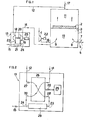
- Figure 1 shows an application of the invention to industrial drying in closed circuit, using turbine-like means for partly expanding the higher moisture gas/vapor stream and turbocompressor-like means for partly compressing the lower moisture gas/vapor stream and a convergent/divergent nozzle separator for completing said partial expansion and said partial compression and for extracting the liquid condensate resulting from the total expansion.
- Figure 2 shows for the same application as Figure 1 a thermodynamic separator using a wave pressure exchanger with one step of compression and expansion instead of the turbine-like and turbocompressor-like means shown in Figure 1.
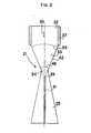
- Figure 3 shows in more details a convergent/divergent nozzle separator as referred to in Figures 1 and 2.
- drying takes place in an enclosure 1 in which an aggregate, for instance wet germinated barley 2, stays on a tray 3.
- the blower 4 operates together with the burner 5 which is fed with combustion air 6 and fuel 7, producing combustion gases 8 which are mixed with the drying air 9.
- the burner 5 is controlled so as to maintain in the lower part 10 of the enclosure 1 the drying air temperature at the required level.
- thermodynamic separator 13 separates the incoming stream of moist air into an outgoing main stream 14 of hot air with reduced moisture content and an outgoing diverted stream 15, composed essentially of cold water which is then rejected for disposal.
- the main stream is driven through the duct 14 up to location 9 where it runs again along the drying circuit.
- the blower 4 driven by motor 22 injects fresh air at location 9 through duct 16 in order to compensate for leaks, losses and rejects of air to the outside atmosphere.
- the aerodynamic separator 13 performs said separation as follows.
- the higher moisture stream coming in through duct 12 undergoes an adiabatic expansion in turbine 18 connected by shaft 20 to turbocompressor 19.
- the cooled stream at low pressure, containing liquid condensate, leaves the turbine at 23 to enter an aerodynamic separator 21 consisting in a convergent/divergent nozzle without moving part wherein said liquid is extracted, according to the following steps:
- the hot lower moisture stream leaving the aerodynamic separator 21 at 24 enters the turbocompressor 19 where it is compressed to the pressure level required to enable the hot stream to be reinjected through duct 14 at location 9.
- an electric motor 25 provides the required additional mechanical work.
- the aerodynamic separator 21 is of a type described in European Patent Application 0 162 509, which normally requires auxiliary means to initiate and enhance the condensation process in the nozzle. As used herein, said auxiliary means are not required, because the stream entering said aerodynamic separator already contains droplets of liquid condensate and other condensation nuclei resulting from the partial expansion of the stream in turbine 18.
- separator is shown in more detail in Figure 3, where the separator enclosure 42 has the general shape of an axisymmetric nozzle comprizing a cylindrical chamber 32, a convergent truncated cone 33, a throat 34 and a divergent 35. As shown in Figure 3 these elements are linked in such a way as to avoid angular points in the axial cross-section of the nozzle.
- the general direction of the moist air flowing into the nozzle is shown by the arrow 36.
- the moist air entering the chamber 32 may be submitted in this chamber to an acoustic radiation generated from the annular enclosure 37 by generators of sonic waves of any known type, so that at the inlet section of the air in the convergent part 33, the wave front has the shape of a spherical surface 38 of which the geometric center is located at a point 39 which is on the axis of the nozzle, downstream the minimal section of its throat 34.
- droplets are then collected in a hollow cylindrical collector 41, having a small diameter, and located along the axis of the divergent part 35 of the nozzle, and of which the circular inlet cross-section is centered at point 39 or slightly behind this point along the direction of the flow.
- the air stream from which the droplets were thus swept away in the region of the throat of the nozzle enters the divergent part 35 where it undergoes an adiabatic, quasi-isentropic recompression transforming into enthalpy the kinetic energy it has in the throat of the nozzle.
- thermodynamic separator 13 performs its function as follows.
- the higher moisture stream coming in through duct 12 undergoes an adiabatic expansion in wave pressure exchanger 26 connected by shaft 20 to motor 25.
- Said stream enters said exchanger through port 27 and leaves it through port 28, cooled and at low pressure, and containing liquid condensate, to enter at 23 the aerodynamic separator 29 which is similar to separator 21 described above except that it enables acoustic condensation in addition to the condensation resulting from steady state expansion.
- the hot lower moisture stream leaving the aerodynamic separator 29 at 24 enters the wave pressure exchanger 26 through port 30 and leaves through port 31 after having been recompressed to the pressure level required to enable the hot stream to be reinjected through duct 14 at location 9.
- the electric motor 25 provides through shaft 20 the additional mechanical work required.
- the aerodynamic separator 29 is of a type described in European Patent Application 0 162 509, which normally requires auxiliary means to initiate and enhance the condensation process in the nozzle, and to create acoustic radiation for performing acoustic agglomeration and acoustic condensation.
- said auxiliary means are not required, because the stream entering said aerodynamic separator already contains droplets of liquid condensate and other condensation nuclei resulting from the partial expansion of the stream in wave pressure exchanger 26, and also contains very intense acoustic radiation which is a result of the wave pressure exchange process.
- An important factor in the energetic efficiency of wave pressure exchangers is impedance matching of the driver and driven gases.
- An impedance matched interface between two gases allows a sound or a shock wave to proceed from one gas into the other without any wave reflections at the interface.
- this requirement means that the product of density and sound speed, as well as the specific heat ratio k , must be the same on each side of the interface.
- a dry gas/vapor mixture where only the gas phase is present
- a wet gas/vapor mixture where both gas and liquid phases are present
- Such prevention is possible, due to the existence of a time lag between the sudden expansion of a gas/vapor mixture and the actual condensation. Said time lag varies with factors which include the pressure ratio of the expansion. Therefore it is important to keep the pressure ratio of each expansion step in the wave pressure exchanger below the critical value above which condensation would occur at locations where it would cause parasitic wave reflections with corresponding energy losses.
- each step of the expansion of the main stream in the wave pressure exchanger is followed by a separation of the liquid condensate resulting from said expansion step.
- said separation may be performed in a curved duct by inertial diffusion of the droplets of condensate through said stream up to collecting means intersecting the paths of said droplets, said duct and said stream following a substantially helical path around the axis of the rotor of the wave pressure exchanger, said helical path having an angle equal or close to the angle of said stream at the outlet port of said exchanger.
- composition of the condensate thus obtained results from the composition of the gaseous mixture which is processed.
- the condensate will not be pure water, but a solution in water of one or several constituents of said flue gases, such as SO2, NO, NO2, CO2, ... .
- This particular feature enables to separate easily, not only condensable vapors, but also gases difficult to condense, provided they are soluble in the condensate of easily condensable vapors. Said vapors can thus have a sweeper or scavenger action.
- scavenging vapor into the carrier gas is insufficient to sweep out of said carrier gas specific gases to be separated, or if its scavenging capacity is insufficient, one may add to the mixture to be separated, before processing it, an additional constituent under gaseous and/or liquid and/or solid form (droplets or particles in suspension), which is able to act as a sweeper or scavenger of said specific gases.
- an additional constituent under gaseous and/or liquid and/or solid form droplets or particles in suspension
- sulphur dioxide SO2 can be absorbed very easily by added citric acid, or acetic acid of which the vapor is easily condensed, and easily absorbed by the condensate of water vapor. Said sulphur dioxide can thus be integrally swept out, and recovered by processing the separated liquid by any known means.
- the range of vapors and gases which can be extracted by the process and apparatus according to the embodiment of the invention shown in Figure 2 is very wide, as the ratio between the initial pressure of the gaseous mixture to be processed and the minimal instantaneous pressure within the flowing mixture may be very high. Indeed this ratio is the product of the pressure ratio of the steady component of the expansion and the pressure ratio of the oscillatory component of the the expansion. The greater the global pressure ratio thus obtained, the greater is the enthalpy drop after expansion, the greater is the corresponding temperature drop, and the more efficient is the separation achieved by condensation.
- the invention is applicable without any restriction to the extraction of any liquid from an aggregate.
- Said aggregate may be a mixture or a combination of different chemical or isotopic components in any proportions.
- the liquid to be extracted can be a simple substance or a mixture or a combination of different chemical or isotopic components in any proportion.
- the carrier gas can be composed of any constituents in any proportions.
- the expressions convergent/divergent nozzle, convergent part, divergent part, throat, throat region, places which intersect the paths of the droplets, duct, as used in this specification and in the appended claims, must be understood in a broad sense which not only applies to Venturi-like nozzle separators, but also to other types of separators which may or maynot be axisymmetrical, with or without a rectilinear or curved axis, wherein the cross section of the stream is progressively reduced to cause said stream to accelerate, then kept constant along some lengths, then progressively increased again to cause said stream to decelerate.
- Such a separator may consist in an enclosure having a cylindrical outer wall with a constant circular cross section and a rectilinear axis, a circular cross section at the inlet and outlet of the fluid stream, and within which an axisymmetrical body centered along the same axis causes for the fluid stream to change from circular to progressively reduced annular cross section, then a constant annular cross section for some length (throat and throat region) then a progressively increasing annular cross section becoming again circular towards the outlet of the separator.
- Such separator may have means causing the flow to follow helical paths only within said throat region. Paths of the droplets must also be understood as including the streamlines of liquid condensate flow resulting from the grouping of the droplets.
- turbine and compressors are also to be understood not only as single units, but also as groups of such units in series or in parallel.
Landscapes
- Chemical & Material Sciences (AREA)
- Physics & Mathematics (AREA)
- Thermal Sciences (AREA)
- Engineering & Computer Science (AREA)
- Analytical Chemistry (AREA)
- General Chemical & Material Sciences (AREA)
- Oil, Petroleum & Natural Gas (AREA)
- Chemical Kinetics & Catalysis (AREA)
- Vaporization, Distillation, Condensation, Sublimation, And Cold Traps (AREA)
- Engine Equipment That Uses Special Cycles (AREA)
Abstract
There is described a process and an apparatus for extracting at least partially a liquid from an aggregate, by evaporation in a stream of carrier gas, followed by separation of at least a part of said evaporated liquid from said stream of carrier gas, said separation (13) comprising expanding (18) the higher moisture contents stream (12) to a lower pressure such as to effect a cooling and resulting liquid condensation, separating (21) resulting liquid condensate (15) from the gas stream, recompressing (19) the cold stream (24) with retained latent heat of vaporization and thereby further heating said stream, and discharging the resulting heated stream (14) with the lowered moisture content at a section of the circuit where it is recycled or where it is rejected to the atmosphere.… According the the invention, the last part of said expansion and the first part of said compression take place in a nozzle type separator (21) which comprises a convergent part, collecting means of condensate and a divergent part.
Description
- The present invention relates to a process and an apparatus for extracting, in an open or closed circuit, at least partially a liquid from an aggregate, by evaporation in a stream of carrier gas, followed by separation of at least part of said evaporated liquid from said stream of carrier gas, in which the source of energy providing substantially the separation work is the pressure increase of the carrier gas provided by mechanical means driving the carrier gas against all head losses throughout the complete circuit. Said separation comprises expanding the high moisture contents stream to a lower pressure so as to effect cooling and resulting liquid condensation, separating resulting liquid condensate from the gas stream, recompressing the cold stream with retained latent heat of vaporization and thereby further heating said stream, and discharging the resulting heated stream with the lowered moisture content at an appropriate section of the circuit.
- More specifically, the invention relates to the way of putting at work the driving energy which provides the separative work, and of carrying out said separation.
- In this specification, the word evaporation has a very broad meaning which includes the production of vapor within the carrier gas by any mechanism, for instance a chemical reaction such as combustion. Similarly, the word aggregate has a very broad meaning which includes not only materials soaked with a liquid, such as wet wool, wet barley, waste sugar beet pulp, paste of paper or cardboard, plaster, or wet or liquid materials to be dryed such as wood, milk, ... , but also materials reacting with a gas, f.i. by combustion, thus forming a vapor which is a constituent of said reaction gas mixture. The aggregate may thus be for instance methanization gas, natural gas, burnable waste products, fuel oil, coal, peat, brown coal, burning in air. It may also be for instance living materials such as plants growing in a greenhouse, or machinery from which seeping liquids are leaking under liquid or vapor form.
- The terms exergy, exergetic, relate to that fraction of the heat which is convertible in a reversible way into mechanical work, as opposed to anergy, anergetic, which relate to that fraction of the heat which is not convertible into mechanical work. The calorific energy of a substance is the sum of its exergy and its anergy. By extension, the word exergy used herein also may mean mechanical work or any other energy which is convertible into mechanical work without being subject to the limitation imposed by Carnot's principle.
- The expression acoustic condensation relates to the process of transient additional condensation of vapor which occurs within the flow of a gas/vapor mixture undergoing an adiabatic quasi-isentropic expansion when the flowing fluid is submitted to a high intensity acoustic radiation.
- A first main application of the invention is the drying of wet products, and mainly industrial drying, wherein it allows to recover water vapor and its latent heat from air/vapor mixtures, using robust, cheap and compact equipment with low energy consumption, i. e. a blower and a thermodynamic separator, or a combined blower/separator, instead of delicate and expensive apparatus such as the known types of heat pumps. A second main application of the invention is the abatement of acid gases, such as sulphur dioxide and nitrogen oxides, from flue gases produced by combustion in boilers, furnaces, incinerators, through condensation of associated water vapor, using said robust, cheap and compact equipment, the energy consumption of which is small and more than offset by the recovery of the latent heat of condensation of the water vapor.
- A third main application of the invention is the extraction and upgrading of the latent heat of condensation of a vapor in a gas/vapor mixture, using said robust, cheap and compact equipment. Said application includes heating, ventilating and air conditioning processes and installations.
- A fourth main application of the invention is the extraction, for recovery or disposal or any other purpose, of valuable and/or polluting gases and vapors contained in process or waste gases, including used air rejected in the atmosphere by industrial production plants, by gasoline refilling stations for cars, and the like, and also including automobile exhaust gases.
- Other applications of the invention will emerge from its detailed description.
- The background art in the technical field of the invention is examplified by U. S.
Patent 3 854 300 and by European Patent Application 0 162 509. - U. S.
Patent 3 854 300 describes a method of reducing the high moisture contents of a stream of gases by expanding said stream to a lower pressure such as to effect cooling and resulting water vapor condensation, then separating resulting water condensate from the gas stream, then recompressing the cold stream with retained latent heat of vaporization and thereby further heating said stream, and then discharging the resulting heated stream with the lowered moisture content to the atmosphere. - As shown in that document, said moisture containing gas stream may be expanded in a turbine type expansion means providing power therefrom and such power is then utilized in the recompression of the gas stream.
- Said method is a particular application of the Brayton cycle which may be used for heat pumping in drying systems, as described in the following reference:
- J. L'HERMITTE et P. CHEVALIER, "Cycle de Brayton et pompes à chaleur - Développement d'un système de séchage", E. D. F. (Electricité de France) Bulletin de la Direction des Etudes et Recherches Série A,
N o 1, 1981 pp. 17 - 20. - In said reference, para 1. "Présentation du cycle de Brayton" shows the background art relating to the Brayton cycle used in industry, as illustrated by fig. 1 and fig. 2. Para 2. "Applications possibles" shows several categories of applications, as illustrated respectively by figures 3 to 7. Para 3. "Recherche de l'application du cycle de Brayton au séchage des céréales" shows a particular embodiment of a drying process using a Brayton cycle, in which the drying chamber is at atmospheric pressure and no heat exchanger is required functionnally, although an additional heat exchanger with a very limited heat exchange surface may be used to improve the overall coefficient of performance (COP) of the process. The operational flowsheets of said process are illustrated in figures 8 to 10 of the document, and its practical performances are shown in figures 11 to 13 of the document. It is clear that said performances are poor.
- European Patent Application 0 162 509 shows a drying process (and corresponding apparatus) which is substantially a particular application with waste heat recovery of the method described in U. S.
Patent 3 854 300. In said application, the expansion and most of the recompression of the stream of gases take place in an aerodynamic separator having no moving part, composed of a convergent-divergent subsonic nozzle in which inertial separation of the condensate takes place at or near the throat region of said nozzle. The driving energy required by this aerodynamic separator is supplied to the process by a blower which moves the main gaseous stream against all head losses throughout the complete circuit. Auxiliary means may be provided in the inlet plenum of the nozzle in order to initiate and enhance the condensation process. In a particular embodiment of said invention, the expansion of the gaseous stream includes a steady component and an oscillatory component, the latter being obtained by the action, within the flowing fluid, of very intense sonic or ultrasonic waves. The effect of said oscillatory component of the expansion is, on one hand, to induce acoustic agglomeration of the droplets of condensate, on the other hand, to cause transient additional condensation by the particular mechanism described inlines 8 to 13,page 12 of the specification of said application. In the present specification, said mechanism is called "acoustic condensation". - The required acoustic energy is generated mechanically either by the flowing stream itself, or by appropriate transducers, or by the blower supplying the driving energy required by the process.
- According to the abovereferred European Patent Application, the amount of the acoustic energy radiated by the sonic wave only represents a minor fraction of the driving energy required by the process, and the latter energy itself only represents a minor fraction of the mechanical energy produced by the expanding fluid in the convergent part of the nozzle.
- The drying process (and corresponding apparatus) described in the abovereferred European Patent Application has thus the following inherent limitations :
- the maximum pressure ratio of the steady state component of the expansion in the aerodynamic separator cannot exceed an upper limit at which the velocity of sound is reached in the throat of the nozzle; for atmospheric air, said limit is about 1.6 and is not sufficient for enabling per se the self-initiation of condensation during the phase of expansion of the incoming stream;
- when expanding air nearly saturated with water vapor, at pressure ratios not exceeding the latter limit, auxiliary means are required to enable the condensation in the throat region to reach a level close to thermodynamic equilibrium;
- the temperature increase which can be achieved by the process between the outlet and the inlet of the air in the dryer chamber cannot exceed an upper limit of 25 to 30°C, and the condensate quantity which can be extracted by the process cannot exceed 10 to 12 gr H₂O per kg dry air when acoustic condensation is not used;
- acoustic condensation may raise said quantity of condensate at the expense of the additional energy consumption required to provide adequate acoustic energy radiation. - Summarizing the state of the art : the known processes and apparatuses in the field of the invention :
- either have poor exergetic efficiencies and COP's, and therefore they are not economically feasible in general,
- or only have limited applications - It is an object of the present invention to provide an improved process and apparatus for extracting in an open or closed circuit a liquid from an aggregate, by evaporation in a stream of carrier gas, followed by separation of said evaporated liquid from said carrier gas, with an energetic efficiency high enough to enable the process to be economically feasible in a very broad field of applications, without using delicate, expensive and/or bulky apparatuses such as heat pumps.
- It is another object of the invention to provide an improved process and apparatus for separating thermodynamically under liquid form a vapor mixed with a carrier gas in a thermodynamic separator requiring functionnally no heat exchanger and wherein the driving energy providing the separative work is essentially mechanical energy supplied to a rotor of said separator in order to provide compression work of the fluid mixture within said separator.
- Other objects, advantages and features of this invention will become apparent to one skilled in the art upon consideration of the written specification, appended claims and attached drawings.
- In the process and apparatus according to the invention, a carrier gas entering an open circuit, or running in a closed circuit, is used to extract a liquid substance from an aggregate, by evaporation of said substance in said carrier gas. The mixture of said vapor with said carrier gas is then driven through a thermodynamic separator wherein the driving energy supplying the separative work is provided by mechanical means causing a pressure increase of the gas/vapor mixture within the separator. Said separator causes the main stream of carrier gas to lose a part of said vapor substance it contained, while the stream diverted by the separator is substantially said substance in liquid form. Said separation comprises expanding the high moisture contents stream to a lower pressure such as to effect cooling and resulting liquid condensation, separating resulting liquid condensate from the gas stream, recompressing the cold stream with retained latent heat of vaporization and thereby further heating said stream, and discharging the resulting heated stream with the lowered moisture content at a section of the circuit where it is recycled or where it is rejected to the atmosphere without or after substantial recovery of its heat. Both said expansion and said compression are performed substantially adiabatically and at least partly in rotating machinery means wherein the expansion work is used to provide part of the compression work.
- In a first embodiment of the invention, at least part of said expansion takes place in a turbine or other rotating machine having the same performances and at least part of said compression takes place in a turbocompressor or other rotating machine having the same performances. The gaseous stream which leaves the turbine contains liquid condensate under the form of fine droplets and nucleation centers. Said stream is driven to a convergent/divergent nozzle having collecting means for extracting the liquid condensate in or near the throat region of the nozzle. In said nozzle, the last part of said expansion and the first part of said compression are performed, as well as the extraction of the liquid condensate resulting from the expansion. The gaseous stream leaving said nozzle is driven for recompression to the inlet of said rotating machinery means.
- In a second and preferred embodiment of the invention, at least part of said expansion and part of said compression take place, in one of several steps, in a wave pressure exchanger. Before each step of expansion in said exchanger, the liquid condensate is extracted by inertial diffusion through the main stream and separated by collecting means, and the main stream is then driven to the next step of said expansion, or after completion of the expansion and liquid condensate extraction, to the first step of said compression. If said expansion and compression are not fully performed in said rotating machinery means, the last part of said expansion and the first part of said compression are performed, as well as the extraction of the quantity of liquid condensate resulting from the expansion, in a convergent/divergent nozzle as mentioned hereabove.
- The invention brings the following specific advantages.
- The energetic efficiency of the process and apparatus following the first embodiment is appreciably better than that of the known processes and apparatuses, although none of the limitations of some of these processes restrict the applications of the invention.
- The energetic efficiency of the process and apparatus following the second embodiment is still better, although this fact is not at all obvious to one skilled in the art. To the contrary, it may seem obvious to him that wave pressure exchange cannot work properly when applied to a gaseous stream in which a liquid phase is caused to appear, thereby causing considerable parasitic wave reflexion and corresponding energy losses. This subject is commented in the detailed description of the preferred embodiments of the invention.
- Figure 1 shows an application of the invention to industrial drying in closed circuit, using turbine-like means for partly expanding the higher moisture gas/vapor stream and turbocompressor-like means for partly compressing the lower moisture gas/vapor stream and a convergent/divergent nozzle separator for completing said partial expansion and said partial compression and for extracting the liquid condensate resulting from the total expansion.
- Figure 2 shows for the same application as Figure 1 a thermodynamic separator using a wave pressure exchanger with one step of compression and expansion instead of the turbine-like and turbocompressor-like means shown in Figure 1.
- Figure 3 shows in more details a convergent/divergent nozzle separator as referred to in Figures 1 and 2.
- In the application illustrated in Figure 1, drying takes place in an
enclosure 1 in which an aggregate, for instance wet germinatedbarley 2, stays on atray 3. The blower 4 operates together with theburner 5 which is fed withcombustion air 6 andfuel 7, producingcombustion gases 8 which are mixed with the drying air 9. Theburner 5 is controlled so as to maintain in thelower part 10 of theenclosure 1 the drying air temperature at the required level. - Said air then crosses the
wet barley layer 2 and leaves theenclosure 1 through its upper part 11 at a temperature which varies during the drying operation, but which is 40 to 50 °C lower than the temperature in 10. Most of the moist air is sucked from section 11 ofenclosure 1 by thethermodynamic separator 13 throughduct 12. The remaining moist air is rejected into the atmosphere at 17. - The
thermodynamic separator 13 separates the incoming stream of moist air into an outgoingmain stream 14 of hot air with reduced moisture content and an outgoing divertedstream 15, composed essentially of cold water which is then rejected for disposal. The main stream is driven through theduct 14 up to location 9 where it runs again along the drying circuit. The blower 4 driven by motor 22 injects fresh air at location 9 throughduct 16 in order to compensate for leaks, losses and rejects of air to the outside atmosphere. - The
aerodynamic separator 13 performs said separation as follows. The higher moisture stream coming in throughduct 12 undergoes an adiabatic expansion inturbine 18 connected byshaft 20 toturbocompressor 19. The cooled stream at low pressure, containing liquid condensate, leaves the turbine at 23 to enter anaerodynamic separator 21 consisting in a convergent/divergent nozzle without moving part wherein said liquid is extracted, according to the following steps: - (a) accelerating adiabatically and quasi-isentropically the mixture of vapor and carrier gas through the convergent part of a convergent/divergent nozzle to form within the throat of the nozzle an expanded stream of high velocity fluid which contains droplets of liquid substance condensed from the gaseous mixture as a result of its expansion,
- (b) withdrawing the droplets of condensate from the stream within the throat region of the nozzle by collecting means located along the axis and/or the wall of the nozzle at places which intersect the paths of the droplets,
- (c) decelerating adiabatically and quasi-isentropically the high velocity stream of the mixture of carrier gas and remaining vapor in the divergent part of the nozzle.
- The hot lower moisture stream leaving the
aerodynamic separator 21 at 24 enters theturbocompressor 19 where it is compressed to the pressure level required to enable the hot stream to be reinjected throughduct 14 at location 9. As the mechanical work supplied byturbine 18 through theshaft 20 is smaller than the mechanical work absorbed byturbocompressor 19, anelectric motor 25 provides the required additional mechanical work. - When the system is operating under steady state conditions, the power input brought into the circuit by
motors 25 and 22 exactly compensates the total heat losses of the circuit, including the loss by air rejected purposedly at 17 in order to enable said compensation. - The
aerodynamic separator 21 is of a type described in European Patent Application 0 162 509, which normally requires auxiliary means to initiate and enhance the condensation process in the nozzle. As used herein, said auxiliary means are not required, because the stream entering said aerodynamic separator already contains droplets of liquid condensate and other condensation nuclei resulting from the partial expansion of the stream inturbine 18. - Such separator is shown in more detail in Figure 3, where the
separator enclosure 42 has the general shape of an axisymmetric nozzle comprizing acylindrical chamber 32, a convergenttruncated cone 33, athroat 34 and a divergent 35. As shown in Figure 3 these elements are linked in such a way as to avoid angular points in the axial cross-section of the nozzle. The general direction of the moist air flowing into the nozzle is shown by thearrow 36. The moist air entering thechamber 32 may be submitted in this chamber to an acoustic radiation generated from theannular enclosure 37 by generators of sonic waves of any known type, so that at the inlet section of the air in theconvergent part 33, the wave front has the shape of aspherical surface 38 of which the geometric center is located at apoint 39 which is on the axis of the nozzle, downstream the minimal section of itsthroat 34. - An adiabatic, quasi-isentropic expansion of the flowing fluid occurs in the convergent
truncated cone 33. The steady component of this expansion results from the reduction of the cross-section of the fluid stream between the inlet of theconvergent part 33 and thethroat 34 of thenozzle 42. The oscillatory component of this expansion results from the spherical acoustic wave of which the front progresses from 38 to 40. - All the streamlines within the
convergent part 33 have rectilinear paths which are perpendicular to the front of the spherical acoustic waves and which converge toward a focus located atpoint 39. Under the effect of the combined steady and oscillatory expansions of the fluid moving in theconvergent part 33, part of the water vapor contained in the incoming stream of moist air condenses as droplets. As the density of these droplets is larger, by a factor of the order of one thousand, than the density of the moist air entering thethroat 34 of the nozzle, these droplets follow their rectilinear paths towardsfocus 39, and are only slightly deviated by the streamlines of dehumidified air which they cross within thethroat 34 of the nozzle. - These droplets are then collected in a hollow
cylindrical collector 41, having a small diameter, and located along the axis of thedivergent part 35 of the nozzle, and of which the circular inlet cross-section is centered atpoint 39 or slightly behind this point along the direction of the flow. The air stream from which the droplets were thus swept away in the region of the throat of the nozzle enters thedivergent part 35 where it undergoes an adiabatic, quasi-isentropic recompression transforming into enthalpy the kinetic energy it has in the throat of the nozzle. - In the preferred embodiment of the invention shown in Figure 2, the
thermodynamic separator 13 performs its function as follows. The higher moisture stream coming in throughduct 12 undergoes an adiabatic expansion inwave pressure exchanger 26 connected byshaft 20 tomotor 25. Said stream enters said exchanger throughport 27 and leaves it throughport 28, cooled and at low pressure, and containing liquid condensate, to enter at 23 theaerodynamic separator 29 which is similar toseparator 21 described above except that it enables acoustic condensation in addition to the condensation resulting from steady state expansion. The hot lower moisture stream leaving theaerodynamic separator 29 at 24 enters thewave pressure exchanger 26 throughport 30 and leaves through port 31 after having been recompressed to the pressure level required to enable the hot stream to be reinjected throughduct 14 at location 9. As the mechanical work supplied by the expanding stream in the wave pressure exchanger is smaller than the mechanical work absorbed by the compression of the stream in said rotating machine, theelectric motor 25 provides throughshaft 20 the additional mechanical work required. - The
aerodynamic separator 29 is of a type described in European Patent Application 0 162 509, which normally requires auxiliary means to initiate and enhance the condensation process in the nozzle, and to create acoustic radiation for performing acoustic agglomeration and acoustic condensation. As used herein, said auxiliary means are not required, because the stream entering said aerodynamic separator already contains droplets of liquid condensate and other condensation nuclei resulting from the partial expansion of the stream inwave pressure exchanger 26, and also contains very intense acoustic radiation which is a result of the wave pressure exchange process. - An important factor in the energetic efficiency of wave pressure exchangers is impedance matching of the driver and driven gases. An impedance matched interface between two gases allows a sound or a shock wave to proceed from one gas into the other without any wave reflections at the interface. In terms of the gas conditions at the interface, this requirement means that the product of density and sound speed, as well as the specific heat ratio k, must be the same on each side of the interface. As these characteristics are very different for respectively a dry gas/vapor mixture (where only the gas phase is present) and a wet gas/vapor mixture (where both gas and liquid phases are present), it is important to prevent condensation while the wave pressure exchange proceeds. Such prevention is possible, due to the existence of a time lag between the sudden expansion of a gas/vapor mixture and the actual condensation. Said time lag varies with factors which include the pressure ratio of the expansion. Therefore it is important to keep the pressure ratio of each expansion step in the wave pressure exchanger below the critical value above which condensation would occur at locations where it would cause parasitic wave reflections with corresponding energy losses.
- According to the invention, each step of the expansion of the main stream in the wave pressure exchanger is followed by a separation of the liquid condensate resulting from said expansion step. Unless otherwise provided for specifically in this application, said separation may be performed in a curved duct by inertial diffusion of the droplets of condensate through said stream up to collecting means intersecting the paths of said droplets, said duct and said stream following a substantially helical path around the axis of the rotor of the wave pressure exchanger, said helical path having an angle equal or close to the angle of said stream at the outlet port of said exchanger.
- Although the description of the process and apparatus according to the invention has been made for the particular application to industrial drying, said process using similar apparatus is applicable in any case where at least one constituent of any gaseous mixture can be extracted from said mixture through an adiabatic, quasi-isentropic expansion causing said constituent to get partially condensed, and then separated under condensed form.
- The composition of the condensate thus obtained results from the composition of the gaseous mixture which is processed. For instance if the process according to the invention is applied to flue gases from industrial boilers burning coal, the condensate will not be pure water, but a solution in water of one or several constituents of said flue gases, such as SO₂, NO, NO₂, CO₂, ... .
- This particular feature enables to separate easily, not only condensable vapors, but also gases difficult to condense, provided they are soluble in the condensate of easily condensable vapors. Said vapors can thus have a sweeper or scavenger action.
- In case the contents of said scavenging vapor into the carrier gas is insufficient to sweep out of said carrier gas specific gases to be separated, or if its scavenging capacity is insufficient, one may add to the mixture to be separated, before processing it, an additional constituent under gaseous and/or liquid and/or solid form (droplets or particles in suspension), which is able to act as a sweeper or scavenger of said specific gases. For instance sulphur dioxide SO₂ can be absorbed very easily by added citric acid, or acetic acid of which the vapor is easily condensed, and easily absorbed by the condensate of water vapor. Said sulphur dioxide can thus be integrally swept out, and recovered by processing the separated liquid by any known means.
- The range of vapors and gases which can be extracted by the process and apparatus according to the embodiment of the invention shown in Figure 2 is very wide, as the ratio between the initial pressure of the gaseous mixture to be processed and the minimal instantaneous pressure within the flowing mixture may be very high. Indeed this ratio is the product of the pressure ratio of the steady component of the expansion and the pressure ratio of the oscillatory component of the the expansion. The greater the global pressure ratio thus obtained, the greater is the enthalpy drop after expansion, the greater is the corresponding temperature drop, and the more efficient is the separation achieved by condensation.
- In fact, the invention is applicable without any restriction to the extraction of any liquid from an aggregate. Said aggregate may be a mixture or a combination of different chemical or isotopic components in any proportions. The liquid to be extracted can be a simple substance or a mixture or a combination of different chemical or isotopic components in any proportion. The carrier gas can be composed of any constituents in any proportions.
- As many possible embodiments may be made of the invention without departing from the scope thereof, it is to be understood that all matter herein set forth or shown in the accompanying drawings is to be interpreted in an illustrative and not in a limiting sense.
- In particular, the expressions convergent/divergent nozzle, convergent part, divergent part, throat, throat region, places which intersect the paths of the droplets, duct, as used in this specification and in the appended claims, must be understood in a broad sense which not only applies to Venturi-like nozzle separators, but also to other types of separators which may or maynot be axisymmetrical, with or without a rectilinear or curved axis, wherein the cross section of the stream is progressively reduced to cause said stream to accelerate, then kept constant along some lengths, then progressively increased again to cause said stream to decelerate. For instance such a separator may consist in an enclosure having a cylindrical outer wall with a constant circular cross section and a rectilinear axis, a circular cross section at the inlet and outlet of the fluid stream, and within which an axisymmetrical body centered along the same axis causes for the fluid stream to change from circular to progressively reduced annular cross section, then a constant annular cross section for some length (throat and throat region) then a progressively increasing annular cross section becoming again circular towards the outlet of the separator. Such separator may have means causing the flow to follow helical paths only within said throat region. Paths of the droplets must also be understood as including the streamlines of liquid condensate flow resulting from the grouping of the droplets. The words turbine and compressors are also to be understood not only as single units, but also as groups of such units in series or in parallel.
Claims (11)
1. A process for extracting, in an open or closed circuit, at least partially a liquid from an aggregate, by evaporation in a stream of carrier gas, followed by separation of at least a part of said evaporated liquid from said stream of carrier gas, said separation comprising expanding the higher moisture contents stream to a lower pressure such as to effect a cooling and resulting liquid condensation, separating resulting liquid condensate from the gas stream, recompressing the cold stream with retained latent heat of vaporization and thereby further heating said stream, and discharging the resulting heated stream with the lowered moisture content at a section of the circuit where it is recycled or where it is rejected to the atmosphere without or after substantial recovery of its heat, both said expansion and said compression being performed substantially adiabatically and at least partly in rotating machinery means wherein the expansion work is used to provide part of the compression work, characterized in that said rotating machinery means perform at least one step of wave pressure exchange.
2. A process for extracting, in an open or closed circuit, at least partially a liquid from an aggregate, by evaporation in a stream of carrier gas, followed by separation of at least a part of said evaporated liquid from said stream of carrier gas, said separation comprising expanding the higher moisture contents stream to a lower pressure such as to effect a cooling and resulting liquid condensation, separating resulting liquid condensate from the gas stream, recompressing the cold stream with retained latent heat of vaporization and thereby further heating said stream, and discharging the resulting heated stream with the lowered moisture content at a section of the circuit where it is recycled or where it is rejected to the atmosphere without or after substantial recovery of its heat, both said expansion and said compression being performed substantially adiabatically and at least partly in rotating machinery means wherein the expansion work is used to provide part of the compression work, characterized in that the last part of said expansion and the first part of said compression both take place in a nozzle type separator without moving part wherein said liquid condensate is extracted, according to the following steps :
(a) accelerating adiabatically and quasi-isentropically the mixture of vapor and carrier gas through the convergent part of a convergent/divergent nozzle to form within the throat of the nozzle an expanded stream of high velocity fluid which contains droplets of liquid substance condensed from the gaseous mixture as a result of its expansion.
(b) withdrawing the droplets of condensate from the stream within the throat region of the nozzle by collecting means located along the axis and/or the wall of the nozzle at places which intersect the paths of the droplets,
(c) decelerating adiabatically and quasi-isentropically the high velocity stream of the mixture of carrier gas and remaining vapor in the divergent part of the nozzle.
3. The process of claim 1, characterized in that the last part of said expansion and the first part of said compression both take place in a nozzle type separator without moving part wherein said liquid condensate is extracted according to the steps (a) to (c) of claim 2 and wherein acoustic agglomeration and acoustic condensation are performed, the source of acoustic radiation being the acoustic energy originating from the wave pressure exchanger as a result of the wave pressure exchange process.
4. The process of claim 1, characterized in that each step of the expansion of said stream in the wave pressure exchanger is preceded by separation of the liquid condensate resulting from previous expansion.
5. The process of claim 4, characterized in that for each step of the expansion of said stream in the wave pressure exchanger the pressure ratio is kept below the critical level above which condensation would occur at locations where it would cause parasitic wave reflections with corresponding energy losses.
6. The process of claim 4, characterized in that each said separation of liquid condensate which doesnot take place in the nozzle type separator wherein the last part of the expansion of said stream may be provided is performed by inertial diffusion of the droplets of condensate through said stream up to collecting means intersecting the paths of said droplets, said stream following a substantially helical path around the axis of the rotor of the wave pressure exchanger, said helical path having an angle equal or close to the angle of said stream at the outlet port of said exchanger.
7. An apparatus for extracting, in an open or closed circuit, at least partially a liquid from an aggregate, by evaporation in a stream of carrier gas, followed by separation of at least a part of said evaporated liquid from said stream of carrier gas, said separation comprising expanding the higher moisture contents stream to a lower pressure such as to effect a cooling and resulting liquid condensation, separating resulting liquid condensate from the gas stream, recompressing the cold stream with retained latent heat of vaporization and thereby further heating said stream, and discharging the resulting heated stream with the lowered moisture content at a section of the circuit where it is recycled or where it is rejected to the atmosphere without or after substantial recovery of its heat, both said expansion and said compression being performed substantially adiabatically and at least partly in rotating machinery means wherein the expansion work is used to provide part of the compression work, characterized in that said rotating machinery means comprise a wave pressure exchanger.
8. An apparatus for extracting, in an open or closed circuit, at least partially a liquid from an aggregate, by evaporation in a stream of carrier gas, followed by separation of at least a part of said evaporated liquid from said stream of carrier gas, said separation comprising expanding the higher moisture contents stream to a lower pressure such as to effect a cooling and resulting liquid condensation, separating resulting liquid condensate from the gas stream, recompressing the cold stream with retained latent heat of vaporization and thereby further heating said stream, and discharging the resulting heated stream with the lowered moisture content at a section of the circuit where it is recycled or where it is rejected to the atmosphere without or after substantial recovery of its heat, both said expansion and said compression being performed substantially adiabatically and at least partly in rotating machinery means wherein the expansion work is used to provide part of the compression work, characterized in that the last part of said expansion and the first part of said compression both take place in a nozzle type separator which comprises :
(a) a convergent/divergent nozzle having a throat region, for causing the mixture of vapor and carrier gas to form within said throat region an adiabatically and quasi-isentropically expanded stream of high velocity fluid which contains droplets of liquid substance condensed from the gaseous mixture as a result of its expansion
(b) collecting means located along the axis and/or along the wall of the nozzle at places which intersect the paths of said droplets of condensate, for causing their adiabatic and quasi-isentropic withdrawal from the stream within said throat region
(c) means for causing the stream of high velocity fluid leaving the throat of the nozzle to decelerate adiabatically and quasi-isentropically within the divergent part of the nozzle.
9. The apparatus of claim 7, characterized in that the last part of said expansion and the first part of said compression both take place in an aerodynamic separator comprising the means (a) to (c) of claim 8.
10. The apparatus of claim 7, characterized in that liquid condensate extraction means are provided, streamwise, before the inlet ports of the wave pressure exchanger through which partially expanded main gaseous stream enters said exchanger for further expansion or for recompression.
11. The apparatus of claim 10 characterized in that said extraction means comprise curved ducts for inertial diffusion of the droplets of condensate through said stream having collecting means intersecting the paths of said droplets, said ducts following a substantially helical path around the axis of the rotor of the wave pressure exchanger with an angle equal or close to the angle of said stream at the outlet port of said exchanger.
Applications Claiming Priority (2)
| Application Number | Priority Date | Filing Date | Title |
|---|---|---|---|
| LU86156A LU86156A1 (en) | 1985-11-12 | 1985-11-12 | METHOD AND DEVICE FOR EXTRACTING LIQUIDS FROM AGGREGATE AND VAPOR GAS MIXTURES |
| LU86156 | 1985-11-12 |
Publications (1)
| Publication Number | Publication Date |
|---|---|
| EP0227628A1 true EP0227628A1 (en) | 1987-07-01 |
Family
ID=19730581
Family Applications (1)
| Application Number | Title | Priority Date | Filing Date |
|---|---|---|---|
| EP86870162A Withdrawn EP0227628A1 (en) | 1985-11-12 | 1986-11-05 | Process and apparatus for extracting liquids from aggregates and from gas/vapor mixtures |
Country Status (5)
| Country | Link |
|---|---|
| US (1) | US4860547A (en) |
| EP (1) | EP0227628A1 (en) |
| JP (1) | JPS62114601A (en) |
| CA (1) | CA1280889C (en) |
| LU (1) | LU86156A1 (en) |
Cited By (2)
| Publication number | Priority date | Publication date | Assignee | Title |
|---|---|---|---|---|
| EP0297200A1 (en) * | 1986-04-04 | 1989-01-04 | Hernandez de Los Angeles, Manuel | Process and apparatus for the direct recovery of water by condensation of atmospheric water vapour, using wind and/or solar energy |
| WO2010104238A1 (en) * | 2009-03-13 | 2010-09-16 | 주식회사 에이앤디코퍼레이션 | Substrate processing apparatus using high-pressure processor and gas recycling method of high-pressure processor |
Families Citing this family (9)
| Publication number | Priority date | Publication date | Assignee | Title |
|---|---|---|---|---|
| WO2000068566A2 (en) | 1999-04-26 | 2000-11-16 | Advanced Research & Technology Institute | Wave rotor detonation engine |
| AU2002218781A1 (en) | 2000-07-06 | 2002-01-21 | Advanced Research & Technology Institute | Partitioned multi-channel combustor |
| US6540917B1 (en) | 2000-11-10 | 2003-04-01 | Purolator Facet Inc. | Cyclonic inertial fluid cleaning apparatus |
| US6845620B2 (en) | 2001-07-06 | 2005-01-25 | Mohamed Razi Nalim | Rotary ejector enhanced pulsed detonation system and method |
| WO2006070894A1 (en) * | 2004-12-29 | 2006-07-06 | Ultrasound Brewery | Method for ultrasonic separation of solution and ultrasonic separation apparatus for use in the method |
| JP4758846B2 (en) * | 2005-11-18 | 2011-08-31 | 東京エレクトロン株式会社 | Drying apparatus, drying method, and drying program, and substrate processing apparatus, substrate processing method, and substrate processing program having the same |
| JP5787310B2 (en) * | 2011-03-15 | 2015-09-30 | ナノミストテクノロジーズ株式会社 | Separation device and separation method |
| JP6371738B2 (en) * | 2015-05-28 | 2018-08-08 | 株式会社東芝 | Deposition equipment |
| WO2019209127A1 (en) * | 2018-04-27 | 2019-10-31 | Bicafé - Torrefecção E Comércio De Café, Lda. | System for extracting a caffeine-rich powder |
Citations (1)
| Publication number | Priority date | Publication date | Assignee | Title |
|---|---|---|---|---|
| US3854300A (en) * | 1973-06-08 | 1974-12-17 | Universal Oil Prod Co | Water vapor removal from vent gas systems |
Family Cites Families (44)
| Publication number | Priority date | Publication date | Assignee | Title |
|---|---|---|---|---|
| GB553208A (en) * | ||||
| BE514256A (en) * | ||||
| GB190602818A (en) * | 1906-02-05 | 1907-02-05 | Ludwik Knauff | Improved Process of and Apparatus for Converting the Pressure or Gas Energy liberated by the Heating or Cooling of Gases or Vapours or by the Explosion of Gases or Vapours into Mechanical Work. |
| GB190608273A (en) * | 1906-04-05 | 1907-03-14 | Ludwik Knauff | Improved Method of and Means for Converting the Internal Energy of Gases and Vapours into Mechanical Work and Vice Versa. |
| GB290669A (en) * | 1927-05-20 | 1928-10-04 | Francois Lebre | Method and apparatus for compressing fluids |
| DE485386C (en) * | 1928-07-22 | 1929-11-02 | Hans Burghard Dipl Ing | Process for compressing gases |
| US2399394A (en) * | 1940-12-07 | 1946-04-30 | Bbc Brown Boveri & Cie | Pressure exchanger |
| US2461186A (en) * | 1942-02-20 | 1949-02-08 | Bbc Brown Boveri & Cie | Gas turbine installation |
| US2453923A (en) * | 1946-08-20 | 1948-11-16 | Douglas Aircraft Co Inc | Aircraft cooling by air turbine means |
| NL144512C (en) * | 1948-01-26 | |||
| US2716289A (en) * | 1952-07-19 | 1955-08-30 | Smith Corp A O | Method and apparatus for the slow drying of stored material |
| NL87758C (en) * | 1954-06-30 | |||
| US2832665A (en) * | 1954-12-23 | 1958-04-29 | Cornell Aeronautical Labor Inc | Method and apparatus for carrying out gas phase reactions which require a high temperature to promote the reaction and rapid cooling to preserve the reaction product |
| GB843912A (en) * | 1955-06-30 | 1960-08-10 | Ronald Denzil Pearson | Improvements in pressure exchangers |
| BE559713A (en) * | 1955-10-05 | |||
| US2902337A (en) * | 1956-12-20 | 1959-09-01 | Cornell Aeronautical Labor Inc | Process for heating and cooling gases and apparatus therefor |
| GB859607A (en) * | 1958-06-25 | 1961-01-25 | John Macbean Neil | Improvements in devices for the removal of undesired solids in suspense from gases, vapours or liquids |
| US3109721A (en) * | 1958-11-21 | 1963-11-05 | Union Carbide Corp | Method and apparatus for separating a fluid mixture by sonic energy |
| US3026966A (en) * | 1959-03-09 | 1962-03-27 | Macrosonics Corp | Ultrasonic demister |
| US3258895A (en) * | 1962-10-19 | 1966-07-05 | Joy Mfg Co | Device for separating solids from a gaseous medium |
| US3230923A (en) * | 1962-11-21 | 1966-01-25 | Sonic Dev Corp | Sonic pressure wave generator |
| US3226948A (en) * | 1964-10-07 | 1966-01-04 | Ingersoll Rand Co | Dehumidifying apparatus |
| US3384117A (en) * | 1966-02-01 | 1968-05-21 | Sun Oil Co | Fluid transfer in wave reactors and the like |
| US3616616A (en) * | 1968-03-11 | 1971-11-02 | Tech Dev Inc | Particle separator especially for use in connection with jet engines |
| US3528217A (en) * | 1968-05-20 | 1970-09-15 | Exxon Production Research Co | Supersonic flow separator with film flow collector |
| GB1283587A (en) * | 1969-08-04 | 1972-07-26 | Mobil Oil Corp | Separation of components from gaseous streams |
| US3788038A (en) * | 1972-01-12 | 1974-01-29 | Mobil Oil Corp | Process for separating uranium isotopes |
| US3771286A (en) * | 1972-02-04 | 1973-11-13 | Chubb Ind Ltd | Method of coagulating aerosols |
| US3839846A (en) * | 1972-05-03 | 1974-10-08 | Teller Environmental Systems | Process and apparatus for treatment of jet engine exhaust |
| US3832666A (en) * | 1973-07-27 | 1974-08-27 | Itt | Electric fuse |
| US3998711A (en) * | 1975-11-28 | 1976-12-21 | Mathematical Sciences Northwest, Inc. | Method for continuously carrying out a gas phase reaction and apparatus therefor |
| US3977850A (en) * | 1976-02-17 | 1976-08-31 | Combustion Engineering, Inc. | Centrifugal separator |
| US4021215A (en) * | 1976-05-03 | 1977-05-03 | United Technologies Corporation | Dual combined cycle air-conditioning system |
| US4198359A (en) * | 1976-07-26 | 1980-04-15 | Todd John J | Apparatus for gasification of liquids |
| US4311494A (en) | 1977-09-26 | 1982-01-19 | Facet Enterprises, Inc. | Axial flow gas cleaning device |
| US4134216A (en) * | 1977-11-18 | 1979-01-16 | Stevens Robert D | Product drying apparatus |
| FR2444882A1 (en) * | 1978-12-18 | 1980-07-18 | Pipeline Service Sa | METHOD FOR DRYING AND GASTING VACUUM OF PIPES |
| US4447965A (en) * | 1980-06-04 | 1984-05-15 | General Electric Company | Process and apparatus for drying with latent heat recovery |
| FR2535445B1 (en) * | 1982-10-28 | 1987-10-16 | Conditionair Sa | DRYING SYSTEM |
| US4504285A (en) * | 1983-04-15 | 1985-03-12 | Modisette Incorporated | Separation of condensible vapors from gas mixtures |
| BE898745A (en) * | 1984-01-24 | 1984-07-24 | Rech S Et De Dev Ind S A En Ab | METHOD AND APPARATUS FOR SEPARATING A MIXTURE OF FLUIDS |
| EP0162509B1 (en) * | 1984-04-25 | 1989-02-01 | S.A. Separgaz | Process and apparatus for extracting liquids from aggregates and from gas/vapor mixtures |
| LU85336A1 (en) * | 1984-04-25 | 1985-11-27 | Belgonucleaire Sa | EXTRACTION METHOD AND DEVICE |
| LU85708A1 (en) * | 1984-12-21 | 1986-07-17 | Belgonucleaire Sa | Liq. extraction from aggregate by evaporation - e.g. in grain drying then recovering liq. in aerodynamic sepn. to condense liq. |
-
1985
- 1985-11-12 LU LU86156A patent/LU86156A1/en unknown
-
1986
- 1986-11-05 EP EP86870162A patent/EP0227628A1/en not_active Withdrawn
- 1986-11-12 CA CA000522718A patent/CA1280889C/en not_active Expired - Lifetime
- 1986-11-12 JP JP61270835A patent/JPS62114601A/en active Pending
- 1986-11-12 US US06/930,149 patent/US4860547A/en not_active Expired - Fee Related
Patent Citations (1)
| Publication number | Priority date | Publication date | Assignee | Title |
|---|---|---|---|---|
| US3854300A (en) * | 1973-06-08 | 1974-12-17 | Universal Oil Prod Co | Water vapor removal from vent gas systems |
Cited By (2)
| Publication number | Priority date | Publication date | Assignee | Title |
|---|---|---|---|---|
| EP0297200A1 (en) * | 1986-04-04 | 1989-01-04 | Hernandez de Los Angeles, Manuel | Process and apparatus for the direct recovery of water by condensation of atmospheric water vapour, using wind and/or solar energy |
| WO2010104238A1 (en) * | 2009-03-13 | 2010-09-16 | 주식회사 에이앤디코퍼레이션 | Substrate processing apparatus using high-pressure processor and gas recycling method of high-pressure processor |
Also Published As
| Publication number | Publication date |
|---|---|
| US4860547A (en) | 1989-08-29 |
| LU86156A1 (en) | 1987-06-26 |
| CA1280889C (en) | 1991-03-05 |
| JPS62114601A (en) | 1987-05-26 |
Similar Documents
| Publication | Publication Date | Title |
|---|---|---|
| US20210207500A1 (en) | Exhaust-gas treatment device, aircraft propulsion system, and method for treating an exhaust-gas stream | |
| US8104259B2 (en) | Method and system for reducing power plant emissions | |
| US4078390A (en) | Removal and recovery of sulfur dioxide from stack gases | |
| CN101522286B (en) | Method for separating CO2 from a gas flow ,CO2 separating device for carrying out said method , swirl nozzle for a CO2 separating device and use of the CO2 separating device | |
| US3877218A (en) | Brayton cycle system with refrigerated intake and condensed water injection | |
| US6530979B2 (en) | Flue gas cleaner | |
| US5590519A (en) | Combined combustion and exhaust gas cleansing plant | |
| CN101235752B (en) | Power plants that utilize gas turbines for power generation and processes for lowering co2 emissions | |
| US4504285A (en) | Separation of condensible vapors from gas mixtures | |
| US4860547A (en) | Process and apparatus for extracting liquids from aggregates and from gas/vapor mixtures | |
| US5647221A (en) | Pressure exchanging ejector and refrigeration apparatus and method | |
| US3788066A (en) | Refrigerated intake brayton cycle system | |
| US5517978A (en) | Pollution control system for an internal combustion engine | |
| US20040103637A1 (en) | Power system and method | |
| US8221514B2 (en) | Ecologically clean method and apparatus for water harvesting from air | |
| RU2619312C2 (en) | Method and apparatus for separating co2 while cooling with using laval nozzle | |
| US5553591A (en) | Engine power enhancement/pollution control system utilizing vortex air separator | |
| JP2011508139A (en) | Gas turbine system and method employing vaporizable liquid supply apparatus | |
| US3854300A (en) | Water vapor removal from vent gas systems | |
| CN88102403A (en) | The immiscible pairing propellant and the refrigerant that are used for the ejection-type refrigeration system | |
| US5137681A (en) | Method and apparatus for recycling turbine exhaust steam in electrical power generation | |
| US9283502B2 (en) | Inertial extraction system | |
| EP0162509B1 (en) | Process and apparatus for extracting liquids from aggregates and from gas/vapor mixtures | |
| CN100432395C (en) | Gas turbine power generation equipment and air humidifier | |
| Horlock | The evaporative gas turbine [EGT] cycle |
Legal Events
| Date | Code | Title | Description |
|---|---|---|---|
| PUAI | Public reference made under article 153(3) epc to a published international application that has entered the european phase |
Free format text: ORIGINAL CODE: 0009012 |
|
| AK | Designated contracting states |
Kind code of ref document: A1 Designated state(s): AT BE CH DE ES FR GB GR IT LI LU NL SE |
|
| 17P | Request for examination filed |
Effective date: 19870602 |
|
| RAP1 | Party data changed (applicant data changed or rights of an application transferred) |
Owner name: S.A. SEPARGAZ |
|
| 17Q | First examination report despatched |
Effective date: 19881118 |
|
| STAA | Information on the status of an ep patent application or granted ep patent |
Free format text: STATUS: THE APPLICATION IS DEEMED TO BE WITHDRAWN |
|
| 18D | Application deemed to be withdrawn |
Effective date: 19911008 |
|
| RIN1 | Information on inventor provided before grant (corrected) |
Inventor name: MALDAGUE, PIERRE |