EP0227575B1 - Pneumatic tire - Google Patents
Pneumatic tire Download PDFInfo
- Publication number
- EP0227575B1 EP0227575B1 EP86630186A EP86630186A EP0227575B1 EP 0227575 B1 EP0227575 B1 EP 0227575B1 EP 86630186 A EP86630186 A EP 86630186A EP 86630186 A EP86630186 A EP 86630186A EP 0227575 B1 EP0227575 B1 EP 0227575B1
- Authority
- EP
- European Patent Office
- Prior art keywords
- tire
- series
- traction elements
- cords
- tread
- Prior art date
- Legal status (The legal status is an assumption and is not a legal conclusion. Google has not performed a legal analysis and makes no representation as to the accuracy of the status listed.)
- Expired - Lifetime
Links
Images
Classifications
-
- B—PERFORMING OPERATIONS; TRANSPORTING
- B60—VEHICLES IN GENERAL
- B60C—VEHICLE TYRES; TYRE INFLATION; TYRE CHANGING; CONNECTING VALVES TO INFLATABLE ELASTIC BODIES IN GENERAL; DEVICES OR ARRANGEMENTS RELATED TO TYRES
- B60C9/00—Reinforcements or ply arrangement of pneumatic tyres
- B60C9/18—Structure or arrangement of belts or breakers, crown-reinforcing or cushioning layers
- B60C9/20—Structure or arrangement of belts or breakers, crown-reinforcing or cushioning layers built-up from rubberised plies each having all cords arranged substantially parallel
- B60C9/2003—Structure or arrangement of belts or breakers, crown-reinforcing or cushioning layers built-up from rubberised plies each having all cords arranged substantially parallel characterised by the materials of the belt cords
- B60C9/2006—Structure or arrangement of belts or breakers, crown-reinforcing or cushioning layers built-up from rubberised plies each having all cords arranged substantially parallel characterised by the materials of the belt cords consisting of steel cord plies only
-
- B—PERFORMING OPERATIONS; TRANSPORTING
- B60—VEHICLES IN GENERAL
- B60C—VEHICLE TYRES; TYRE INFLATION; TYRE CHANGING; CONNECTING VALVES TO INFLATABLE ELASTIC BODIES IN GENERAL; DEVICES OR ARRANGEMENTS RELATED TO TYRES
- B60C11/00—Tyre tread bands; Tread patterns; Anti-skid inserts
- B60C11/03—Tread patterns
- B60C11/0311—Patterns comprising tread lugs arranged parallel or oblique to the axis of rotation
-
- B—PERFORMING OPERATIONS; TRANSPORTING
- B60—VEHICLES IN GENERAL
- B60C—VEHICLE TYRES; TYRE INFLATION; TYRE CHANGING; CONNECTING VALVES TO INFLATABLE ELASTIC BODIES IN GENERAL; DEVICES OR ARRANGEMENTS RELATED TO TYRES
- B60C9/00—Reinforcements or ply arrangement of pneumatic tyres
- B60C9/02—Carcasses
- B60C9/04—Carcasses the reinforcing cords of each carcass ply arranged in a substantially parallel relationship
- B60C9/08—Carcasses the reinforcing cords of each carcass ply arranged in a substantially parallel relationship the cords extend transversely from bead to bead, i.e. radial ply
-
- Y—GENERAL TAGGING OF NEW TECHNOLOGICAL DEVELOPMENTS; GENERAL TAGGING OF CROSS-SECTIONAL TECHNOLOGIES SPANNING OVER SEVERAL SECTIONS OF THE IPC; TECHNICAL SUBJECTS COVERED BY FORMER USPC CROSS-REFERENCE ART COLLECTIONS [XRACs] AND DIGESTS
- Y10—TECHNICAL SUBJECTS COVERED BY FORMER USPC
- Y10S—TECHNICAL SUBJECTS COVERED BY FORMER USPC CROSS-REFERENCE ART COLLECTIONS [XRACs] AND DIGESTS
- Y10S152/00—Resilient tires and wheels
- Y10S152/902—Non-directional tread pattern having no circumferential rib and having blocks defined by circumferential grooves and transverse grooves
-
- Y—GENERAL TAGGING OF NEW TECHNOLOGICAL DEVELOPMENTS; GENERAL TAGGING OF CROSS-SECTIONAL TECHNOLOGIES SPANNING OVER SEVERAL SECTIONS OF THE IPC; TECHNICAL SUBJECTS COVERED BY FORMER USPC CROSS-REFERENCE ART COLLECTIONS [XRACs] AND DIGESTS
- Y10—TECHNICAL SUBJECTS COVERED BY FORMER USPC
- Y10T—TECHNICAL SUBJECTS COVERED BY FORMER US CLASSIFICATION
- Y10T152/00—Resilient tires and wheels
- Y10T152/10—Tires, resilient
- Y10T152/10495—Pneumatic tire or inner tube
- Y10T152/10765—Characterized by belt or breaker structure
-
- Y—GENERAL TAGGING OF NEW TECHNOLOGICAL DEVELOPMENTS; GENERAL TAGGING OF CROSS-SECTIONAL TECHNOLOGIES SPANNING OVER SEVERAL SECTIONS OF THE IPC; TECHNICAL SUBJECTS COVERED BY FORMER USPC CROSS-REFERENCE ART COLLECTIONS [XRACs] AND DIGESTS
- Y10—TECHNICAL SUBJECTS COVERED BY FORMER USPC
- Y10T—TECHNICAL SUBJECTS COVERED BY FORMER US CLASSIFICATION
- Y10T152/00—Resilient tires and wheels
- Y10T152/10—Tires, resilient
- Y10T152/10495—Pneumatic tire or inner tube
- Y10T152/10855—Characterized by the carcass, carcass material, or physical arrangement of the carcass materials
Definitions
- the present invention relates to pneumatic tires, of the type described in the introductory portion of claim 1. Such a tire is taught, for example, in DE-U-8 502 311.
- a tire according to the present invention is intended for use on a light weight military vehicle, or similar civilian vehicles, slightly larger than the well known Jeep that has been in use since World War II.
- the dimensions of the tire are dictated by the dimensions of the vehicle itself, and the weight of the tire is important because such a vehicle has a specified overall weight.
- the tires may be used in conjunction with a run-flat device, and are required to have a higher resistance to penetration of the tread area by foreign objects than similar sized tires used on civilian type vehicles. This same tire is required to provide good traction under a variety of conditions, such as mud, sand, gravel, and snow.
- the solution to this problem may be inferred from the characterizing part of claim 1.
- a tire manufactured in accordance with the preferred embodiment which is intended for use on a specific military vehicle, has a size of 37 ⁇ 12.50 R 16.5 LT. That is to say, such a tire when mounted on a specified rim and inflated to the specified pressure has a maximum outside diameter of 37 inches (94 cm), a width at the widest portion of the tire of 12.50 inches (32 cm), and a nominal bead diameter of 16.5 inches (42 cm).
- a tire of this size according to the preferred embodiment, has a weight of less than 29.5 kg, and preferably of about 28 kg.
- a tire according to the preferred embodiment has an aspect ratio of about 80.
- a tire according to the preferred embodiment of the invention is intended to be mounted upon a multiple piece rim (not shown) and to have a run-flat device (not shown) disposed within the inflation chamber of the tire
- the terms “axial” and “axially” refer to directions parallel to the axis of rotation of a tire, and the terms “radial” and “radially” refer to directions perpendicular to the axis of rotation of a tire.
- the “aspect ratio” of a tire is the tire's cross-section height divided by the cross-section width.
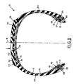
- a pair of axially spaced apart substantially inextensible annular beads 11,12 are disposed concentric with the axis of rotation of the tire.
- a single carcass ply 13 of aramid cords extends between the beads 11, 12 and is anchored around each of the beads.
- the term "aramid” refers to a material that is an aromatic polyamide.
- the aramid cords of the carcass ply are substantially parallel to the next adjacent cords and are disposed at an angle in the range of 80° to 90°, preferably 88° to 90°, with respect to, and at, the mid-circumferential plane M of the tire.
- a tire with this type of carcass ply is commonly referred to as a "radial ply tire”.
- the "mid-circumferential plane" of a tire is a plane disposed perpendicular to the axis of rotation of a tire and midway between the sidewalls of the tire.
- the aramid cords have a denier of 1500/2, a diameter of.7 mm, and are disposed 11 cords per cm as measured perpendicular to the cords.
- a single carcass ply of aramid cords is used in order to get a very strong carcass ply at a very low weight.
- a pair of juxtaposed belt plies 14, 15 of steel cords are disposed radially outwardly of the carcass ply 13 in the crown portion of the tire.
- the steel cords are substantially parallel to next adjacent cords and are disposed at an angle in the range of 18° to 27°, preferably 20° to 25°, most preferably 23° with respect to, and at, the mid-circumferential plane M of the tire.
- the belt plies are not folded, but it is understood that it is within the scope of the invention that one or both of the belt plies could be folded. As illustrated in Fig.
- a tire according to the preferred embodiment has only a single pair of belt plies, but it is understood that a tire in accordance with the broad aspect of the invention could have more than one pair of belt plies.
- the steel cords of the belt plies of a tire according to the preferred embodiment have a construction of 3 x, 20 + 6 x.38, an outside diameter of at least 1.1 mm, preferably 1.2 mm, and are disposed such that there are 2.5 cords per cm, as measured perpendicular to the cords.
- the cords of one belt ply are inclined in a different direction with respect to the mid-circumferential plane from the steel cords of the other belt ply.
- each belt ply is preferably enclosed in a strip of a suitable. elastomeric material (not shown) in a manner that is well known in the tire art.
- the steel cords used in the belt plies of the preferred embodiment are larger than those normally used in a tire of this size, in order to provide a high resistance to penetration of the tread portion of the tire by a foreign object.
- annular elastomeric filler 16 Disposed between the main portion of the carcass ply 13 and the turn-up portion of the carcass ply in each of the bead portions of the tire, there is disposed an annular elastomeric filler 16.
- This annular elastomeric filler strip is sometimes referred to in the tire art as a "bead filler” or an "apex".
- this annular elastomeric filler 16 comprises a radially inner portion 17 of a relatively hard compound to stiffen the bead area of the tire, and a radially outer portion 18 of a relatively soft compound to provide better flexing in the lower sidewall portion of the tire.
- One or more reinforcing layers of fabric are wrapped around the beads in manners well known in the tire art.
- two nylon chippers 35, 36 are disposed on the side of the carcass ply distal from the annular bead.
- An innerliner 19 of a substantially air impervious material is disposed radially and axially inwardly of the single carcass ply 13.
- a ground engaging tread portion 20 is disposed radially outwardly of the belt plies 14, 15.
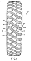
- the structure of the tread portion of a tire according to the preferred embodiment of the invention can best be described by referring to Fig. 2 in conjunction with Fig. 1.
- the tread position 20 has a pair of lateral edges 22, 23 and a plurality of series 31 of independent traction elements 21.
- Each series of traction elements extends from a lateral edge 22, 23 of the tread towards another lateral edge 22, 23 of the tread along a curved path.
- the traction elements in each series of traction elements are separated from the next adjacent traction elements of that same series by straight grooves 24.
- the width of the straight grooves 24 is less than the width of the curved grooves 25 separating circumferentially adjacent series of traction elements.
- the tread portion has a net-to-gross ratio in the range of 45% to 55%, preferably in the range of 49% to 51%.
- the nonskid depth of the tread is in the range of 11 mm to 13 mm, most preferably in the range of 11.2 mm to 11.7 mm.
- each series 31 of traction elements extends from one lateral edge 22, 23 of the tread to the other lateral edge 22, 23 of the tread.
- each series of traction elements includes traction elements that extend to each of the lateral edges of the tread.
- the lateral edges of a tread are determined from the footprint of a tire mounted upon the specified rim, inflated to the specified pressure, and subjected to the rated load.
- the tread portion has a radially outer most layer 39 comprised of one elastomeric compound, selected in accordance with principles well known in the tire, art, and a radially inner layer 40 comprised of the same elastomeric material that is disposed axially outwardly of the carcass ply 13 in each sidewall 37, 38 of the tire.
Description
- The present invention relates to pneumatic tires, of the type described in the introductory portion of claim 1. Such a tire is taught, for example, in DE-U-8 502 311.
- In view of the fact that a military vehicle may be operated under a variety of adverse conditions, both on and off of highways, the tires intended for use on such a vehicle must meet special requirements. A tire according to the present invention is intended for use on a light weight military vehicle, or similar civilian vehicles, slightly larger than the well known Jeep that has been in use since World War II. The dimensions of the tire are dictated by the dimensions of the vehicle itself, and the weight of the tire is important because such a vehicle has a specified overall weight. The tires may be used in conjunction with a run-flat device, and are required to have a higher resistance to penetration of the tread area by foreign objects than similar sized tires used on civilian type vehicles. This same tire is required to provide good traction under a variety of conditions, such as mud, sand, gravel, and snow. The solution to this problem may be inferred from the characterizing part of claim 1.
- The invention can best be described with reference to the accompanying figures of the drawing in which:
- Fig. 1 is a front elevational view of the tread portion of a tire according to the preferred embodiment of the invention; and
- Fig. 2 is a radial cross-sectional view of the tire shown in Fig. 1.
- Referring first to Fig. 2, there is illustrated a radial cross-sectional view of a
tire 10 according to the preferred embodiment of the invention. A tire manufactured in accordance with the preferred embodiment, which is intended for use on a specific military vehicle, has a size of 37 × 12.50 R 16.5 LT. That is to say, such a tire when mounted on a specified rim and inflated to the specified pressure has a maximum outside diameter of 37 inches (94 cm), a width at the widest portion of the tire of 12.50 inches (32 cm), and a nominal bead diameter of 16.5 inches (42 cm). A tire of this size, according to the preferred embodiment, has a weight of less than 29.5 kg, and preferably of about 28 kg. A tire according to the preferred embodiment has an aspect ratio of about 80. A tire according to the preferred embodiment of the invention is intended to be mounted upon a multiple piece rim (not shown) and to have a run-flat device (not shown) disposed within the inflation chamber of the tire - As used herein, and in the appended claims, the terms "axial" and "axially" refer to directions parallel to the axis of rotation of a tire, and the terms "radial" and "radially" refer to directions perpendicular to the axis of rotation of a tire. The "aspect ratio" of a tire is the tire's cross-section height divided by the cross-section width.
- A pair of axially spaced apart substantially inextensible
annular beads 11,12 are disposed concentric with the axis of rotation of the tire. Asingle carcass ply 13 of aramid cords extends between thebeads 11, 12 and is anchored around each of the beads. The term "aramid" refers to a material that is an aromatic polyamide. The aramid cords of the carcass ply are substantially parallel to the next adjacent cords and are disposed at an angle in the range of 80° to 90°, preferably 88° to 90°, with respect to, and at, the mid-circumferential plane M of the tire. A tire with this type of carcass ply is commonly referred to as a "radial ply tire". As used herein and in the appended claims, the "mid-circumferential plane" of a tire is a plane disposed perpendicular to the axis of rotation of a tire and midway between the sidewalls of the tire. In the preferred embodiment, the aramid cords have a denier of 1500/2, a diameter of.7 mm, and are disposed 11 cords per cm as measured perpendicular to the cords. A single carcass ply of aramid cords is used in order to get a very strong carcass ply at a very low weight. - A pair of juxtaposed
belt plies carcass ply 13 in the crown portion of the tire. The steel cords are substantially parallel to next adjacent cords and are disposed at an angle in the range of 18° to 27°, preferably 20° to 25°, most preferably 23° with respect to, and at, the mid-circumferential plane M of the tire. In the preferred embodiment the belt plies are not folded, but it is understood that it is within the scope of the invention that one or both of the belt plies could be folded. As illustrated in Fig. 2, a tire according to the preferred embodiment has only a single pair of belt plies, but it is understood that a tire in accordance with the broad aspect of the invention could have more than one pair of belt plies. The steel cords of the belt plies of a tire according to the preferred embodiment have a construction of 3 x, 20 + 6 x.38, an outside diameter of at least 1.1 mm, preferably 1.2 mm, and are disposed such that there are 2.5 cords per cm, as measured perpendicular to the cords. In accordance with well known tire engineering principles, the cords of one belt ply are inclined in a different direction with respect to the mid-circumferential plane from the steel cords of the other belt ply. The lateral edges of each belt ply are preferably enclosed in a strip of a suitable. elastomeric material (not shown) in a manner that is well known in the tire art. The steel cords used in the belt plies of the preferred embodiment are larger than those normally used in a tire of this size, in order to provide a high resistance to penetration of the tread portion of the tire by a foreign object. - Disposed between the main portion of the
carcass ply 13 and the turn-up portion of the carcass ply in each of the bead portions of the tire, there is disposed an annularelastomeric filler 16. This annular elastomeric filler strip is sometimes referred to in the tire art as a "bead filler" or an "apex". Preferably this annularelastomeric filler 16 comprises a radiallyinner portion 17 of a relatively hard compound to stiffen the bead area of the tire, and a radiallyouter portion 18 of a relatively soft compound to provide better flexing in the lower sidewall portion of the tire. One or more reinforcing layers of fabric are wrapped around the beads in manners well known in the tire art. In the preferred embodiment twonylon chippers innerliner 19 of a substantially air impervious material is disposed radially and axially inwardly of thesingle carcass ply 13. - A ground
engaging tread portion 20 is disposed radially outwardly of thebelt plies tread position 20 has a pair oflateral edges series 31 ofindependent traction elements 21. Each series of traction elements extends from alateral edge lateral edge straight grooves 24. The width of thestraight grooves 24 is less than the width of thecurved grooves 25 separating circumferentially adjacent series of traction elements. The tread portion has a net-to-gross ratio in the range of 45% to 55%, preferably in the range of 49% to 51%. In the preferred embodiment the nonskid depth of the tread, as measured at 26 in Fig. 1, is in the range of 11 mm to 13 mm, most preferably in the range of 11.2 mm to 11.7 mm. In a tire according to the preferred embodiment illustrated in Figs. 1 and 2, eachseries 31 of traction elements extends from onelateral edge lateral edge - It is also considered to be very important to have the proper number of series of traction elements disposed around the circumference of the tire in order to improve the traction of the tire in mud and snow. In a tire according to the preferred embodiment having a nominal rim diameter of 42 cm (16.5 inches) and an outside diameter of 94 cm (37 inches) there are in the range of 28 to 38 series, preferably 30 to 35 and most preferably 33 series of traction elements disposed around the tire
- In the preferred embodiment the tread portion has a radially outer
most layer 39 comprised of one elastomeric compound, selected in accordance with principles well known in the tire, art, and a radiallyinner layer 40 comprised of the same elastomeric material that is disposed axially outwardly of thecarcass ply 13 in eachsidewall
Claims (7)
Applications Claiming Priority (2)
| Application Number | Priority Date | Filing Date | Title |
|---|---|---|---|
| US810433 | 1985-12-18 | ||
| US06/810,433 US4649976A (en) | 1985-12-18 | 1985-12-18 | Pneumatic tire |
Publications (3)
| Publication Number | Publication Date |
|---|---|
| EP0227575A2 EP0227575A2 (en) | 1987-07-01 |
| EP0227575A3 EP0227575A3 (en) | 1988-04-27 |
| EP0227575B1 true EP0227575B1 (en) | 1991-03-20 |
Family
ID=25203845
Family Applications (1)
| Application Number | Title | Priority Date | Filing Date |
|---|---|---|---|
| EP86630186A Expired - Lifetime EP0227575B1 (en) | 1985-12-18 | 1986-12-05 | Pneumatic tire |
Country Status (5)
| Country | Link |
|---|---|
| US (1) | US4649976A (en) |
| EP (1) | EP0227575B1 (en) |
| JP (2) | JPS62155102A (en) |
| CA (1) | CA1245538A (en) |
| DE (1) | DE3678261D1 (en) |
Families Citing this family (24)
| Publication number | Priority date | Publication date | Assignee | Title |
|---|---|---|---|---|
| US4877072A (en) * | 1987-12-17 | 1989-10-31 | The Goodyear Tire & Rubber Company | Tread for left and right vehicle tires |
| JP2708247B2 (en) * | 1989-03-24 | 1998-02-04 | 株式会社ブリヂストン | Heavy duty pneumatic tires |
| JPH0331009A (en) * | 1989-06-27 | 1991-02-08 | Ohtsu Tire & Rubber Co Ltd :The | Tire having lug |
| US5464050A (en) * | 1994-06-20 | 1995-11-07 | The Goodyear Tire & Rubber Company | Non-directional pneumatic tire for use on agricultural tractors and other like vehicles |
| EP0921955B1 (en) * | 1996-08-29 | 2000-05-03 | The Goodyear Tire & Rubber Company | Industrial service agricultural tire |
| CA2279209C (en) * | 1997-02-04 | 2007-08-14 | The Goodyear Tire & Rubber Company | Industrial service agricultural tire |
| US6263933B1 (en) | 1997-02-04 | 2001-07-24 | The Goodyear Tire & Rubber Company | Industrial service agricultural tire |
| USD412302S (en) * | 1998-04-27 | 1999-07-27 | The Goodyear Tire & Rubber Company | Tire tread |
| US6209602B1 (en) | 1999-02-03 | 2001-04-03 | The Goodyear Tire & Rubber Company | Industrial service agricultural tire |
| USD420630S (en) * | 1999-03-09 | 2000-02-15 | The Goodyear Tire & Rubber Company | Tire tread |
| US6293323B1 (en) | 2000-01-27 | 2001-09-25 | The Goodyear Tire & Rubber Company | Off-road tire |
| US6401777B1 (en) | 2000-04-10 | 2002-06-11 | The Goodyear Tire & Rubber Company | Tire chipper construction for runflat tires |
| US20030111152A1 (en) * | 2001-12-06 | 2003-06-19 | Laurent Colantonio | Pneumatic tire bead area construction for improved chafer cracking resistance during run-flat operation |
| US20040112492A1 (en) * | 2002-12-12 | 2004-06-17 | John Kotanides | Tire for inter-city buses and motor coaches |
| US8056202B2 (en) * | 2006-04-27 | 2011-11-15 | Bridgestone Americas Tire Operations, Llc | Tire replacement system for compact tractor |
| FR2904790B1 (en) * | 2006-08-08 | 2008-10-10 | Michelin Soc Tech | TREAD SCULPTURE FOR VEHICLES FOR TRANSPORTING HEAVY LOADS. |
| EP2091760B1 (en) * | 2006-11-24 | 2012-08-15 | Alliance Tire Co. | Agricultural vehicle tire |
| US8136562B2 (en) | 2006-12-29 | 2012-03-20 | Bridgestone Firestone North American Tire, Llc | Tire bead insulation |
| WO2013147748A2 (en) * | 2012-03-27 | 2013-10-03 | Michelin Recherche Et Technique S.A. | Improved wet and snow traction design for a tire thread and solution for pull under torque therefor |
| EP3541640B1 (en) | 2016-11-17 | 2022-08-24 | Bridgestone Americas Tire Operations, LLC | Pneumatic tire having dampening element adhered to air barrier layer |
| JP7124531B2 (en) | 2018-08-01 | 2022-08-24 | 住友ゴム工業株式会社 | tires for rough terrain |
| FR3094271B1 (en) * | 2019-03-29 | 2021-07-30 | Michelin & Cie | Agricultural vehicle tire comprising a tread |
| JP2022531133A (en) | 2019-04-29 | 2022-07-06 | 株式会社ブリヂストン | Side wall support for pneumatic tires |
| USD994588S1 (en) * | 2021-07-28 | 2023-08-08 | The Goodyear Tire & Rubber Company | Tire |
Family Cites Families (11)
| Publication number | Priority date | Publication date | Assignee | Title |
|---|---|---|---|---|
| NL134985C (en) * | 1967-07-27 | |||
| FR2053873A5 (en) * | 1969-07-21 | 1971-04-16 | Michelin & Cie | |
| FR2145414B1 (en) * | 1971-07-13 | 1974-02-15 | Michelin & Cie | |
| BE792556A (en) * | 1971-12-17 | 1973-06-12 | Michelin & Cie | IMPROVEMENTS TO TIRE PACKAGES |
| JPS544123A (en) * | 1977-06-10 | 1979-01-12 | Fuji Photo Optical Co Ltd | Exposure control device for camera |
| US4296789A (en) * | 1978-02-14 | 1981-10-27 | The Goodyear Tire & Rubber Company | Tread for pneumatic tire |
| JPS5546883A (en) * | 1978-09-29 | 1980-04-02 | Hitachi Ltd | Non-crystalline magnetic distortion motor |
| DE2912546A1 (en) * | 1979-03-29 | 1980-10-09 | Continental Gummi Werke Ag | Pneumatic tyre tread for winter roads - with cross lines or blocks broken by V-grooves of changing inclination |
| FR2523521A1 (en) * | 1982-03-22 | 1983-09-23 | Michelin & Cie | TRACK FOR TIRES FOR OFF-ROAD TRAFFIC |
| US4534392A (en) * | 1984-05-16 | 1985-08-13 | The Goodyear Tire & Rubber Company | Tractor tire |
| DE8502311U1 (en) * | 1985-01-30 | 1985-05-30 | Continental Gummi-Werke Ag, 3000 Hannover | Pneumatic tires for high-speed, off-road vehicles |
-
1985
- 1985-12-18 US US06/810,433 patent/US4649976A/en not_active Expired - Lifetime
-
1986
- 1986-12-05 DE DE8686630186T patent/DE3678261D1/en not_active Expired - Fee Related
- 1986-12-05 EP EP86630186A patent/EP0227575B1/en not_active Expired - Lifetime
- 1986-12-12 CA CA000525232A patent/CA1245538A/en not_active Expired
- 1986-12-18 JP JP61300203A patent/JPS62155102A/en active Pending
-
1992
- 1992-11-20 JP JP080480U patent/JPH0627206U/en active Pending
Also Published As
| Publication number | Publication date |
|---|---|
| EP0227575A2 (en) | 1987-07-01 |
| JPS62155102A (en) | 1987-07-10 |
| DE3678261D1 (en) | 1991-04-25 |
| EP0227575A3 (en) | 1988-04-27 |
| CA1245538A (en) | 1988-11-29 |
| US4649976A (en) | 1987-03-17 |
| JPH0627206U (en) | 1994-04-12 |
Similar Documents
| Publication | Publication Date | Title |
|---|---|---|
| EP0227575B1 (en) | Pneumatic tire | |
| EP0590481B1 (en) | Pneumatic tire | |
| US7409974B2 (en) | Self-supporting pneumatic tire with a partial inner liner | |
| CA2005010C (en) | Pneumatic tire | |
| EP0344086B1 (en) | Pneumatic tire | |
| EP0600265B1 (en) | A pneumatic agricultural tire | |
| EP0239521B1 (en) | High performance all-season tire | |
| CA2018817C (en) | Tractor tire | |
| US6481479B1 (en) | High aspect agricultural or off-road tire | |
| EP0329591B1 (en) | Pneumatic tires | |
| EP0313500B1 (en) | Pneumatic tires | |
| US4688617A (en) | Pneumatic tire | |
| US5529102A (en) | Motorcycle radial tire with supplementary breaker ply | |
| GB2283215A (en) | Motor-cycle radial tyre | |
| EP0703102A2 (en) | Motorcycle radial tyre | |
| EP1017574B1 (en) | High aspect agricultural or off-road tire | |
| CA2176279A1 (en) | Low pressure all terrain vehicle tire | |
| US4964452A (en) | Pneumatic tires | |
| EP0547849A1 (en) | Motor-cycle radial tyre | |
| EP0820883A1 (en) | Motor-cycle radial tyre | |
| EP0835767A2 (en) | Motorcycle radial tyre |
Legal Events
| Date | Code | Title | Description |
|---|---|---|---|
| PUAI | Public reference made under article 153(3) epc to a published international application that has entered the european phase |
Free format text: ORIGINAL CODE: 0009012 |
|
| 17P | Request for examination filed |
Effective date: 19861222 |
|
| AK | Designated contracting states |
Kind code of ref document: A2 Designated state(s): BE DE FR GB IT NL SE |
|
| PUAL | Search report despatched |
Free format text: ORIGINAL CODE: 0009013 |
|
| AK | Designated contracting states |
Kind code of ref document: A3 Designated state(s): BE DE FR GB IT NL SE |
|
| 17Q | First examination report despatched |
Effective date: 19900124 |
|
| GRAA | (expected) grant |
Free format text: ORIGINAL CODE: 0009210 |
|
| AK | Designated contracting states |
Kind code of ref document: B1 Designated state(s): BE DE FR GB IT NL SE |
|
| REF | Corresponds to: |
Ref document number: 3678261 Country of ref document: DE Date of ref document: 19910425 |
|
| ET | Fr: translation filed | ||
| ITF | It: translation for a ep patent filed |
Owner name: MODIANO & ASSOCIATI S.R.L. |
|
| PLBE | No opposition filed within time limit |
Free format text: ORIGINAL CODE: 0009261 |
|
| STAA | Information on the status of an ep patent application or granted ep patent |
Free format text: STATUS: NO OPPOSITION FILED WITHIN TIME LIMIT |
|
| 26N | No opposition filed | ||
| EAL | Se: european patent in force in sweden |
Ref document number: 86630186.4 |
|
| PGFP | Annual fee paid to national office [announced via postgrant information from national office to epo] |
Ref country code: NL Payment date: 19960924 Year of fee payment: 11 |
|
| PGFP | Annual fee paid to national office [announced via postgrant information from national office to epo] |
Ref country code: GB Payment date: 19961108 Year of fee payment: 11 |
|
| PGFP | Annual fee paid to national office [announced via postgrant information from national office to epo] |
Ref country code: SE Payment date: 19961119 Year of fee payment: 11 |
|
| PGFP | Annual fee paid to national office [announced via postgrant information from national office to epo] |
Ref country code: FR Payment date: 19961211 Year of fee payment: 11 |
|
| PGFP | Annual fee paid to national office [announced via postgrant information from national office to epo] |
Ref country code: DE Payment date: 19961227 Year of fee payment: 11 |
|
| PGFP | Annual fee paid to national office [announced via postgrant information from national office to epo] |
Ref country code: BE Payment date: 19970108 Year of fee payment: 11 |
|
| PG25 | Lapsed in a contracting state [announced via postgrant information from national office to epo] |
Ref country code: GB Free format text: LAPSE BECAUSE OF NON-PAYMENT OF DUE FEES Effective date: 19971205 |
|
| PG25 | Lapsed in a contracting state [announced via postgrant information from national office to epo] |
Ref country code: SE Free format text: LAPSE BECAUSE OF NON-PAYMENT OF DUE FEES Effective date: 19971206 |
|
| PG25 | Lapsed in a contracting state [announced via postgrant information from national office to epo] |
Ref country code: FR Free format text: THE PATENT HAS BEEN ANNULLED BY A DECISION OF A NATIONAL AUTHORITY Effective date: 19971231 Ref country code: BE Free format text: LAPSE BECAUSE OF NON-PAYMENT OF DUE FEES Effective date: 19971231 |
|
| BERE | Be: lapsed |
Owner name: THE GOODYEAR TIRE & RUBBER CY Effective date: 19971231 |
|
| PG25 | Lapsed in a contracting state [announced via postgrant information from national office to epo] |
Ref country code: NL Free format text: LAPSE BECAUSE OF NON-PAYMENT OF DUE FEES Effective date: 19980701 |
|
| GBPC | Gb: european patent ceased through non-payment of renewal fee |
Effective date: 19971205 |
|
| NLV4 | Nl: lapsed or anulled due to non-payment of the annual fee |
Effective date: 19980701 |
|
| PG25 | Lapsed in a contracting state [announced via postgrant information from national office to epo] |
Ref country code: DE Free format text: LAPSE BECAUSE OF NON-PAYMENT OF DUE FEES Effective date: 19980901 |
|
| EUG | Se: european patent has lapsed |
Ref document number: 86630186.4 |
|
| REG | Reference to a national code |
Ref country code: FR Ref legal event code: ST |
|
| PG25 | Lapsed in a contracting state [announced via postgrant information from national office to epo] |
Ref country code: IT Free format text: LAPSE BECAUSE OF NON-PAYMENT OF DUE FEES;WARNING: LAPSES OF ITALIAN PATENTS WITH EFFECTIVE DATE BEFORE 2007 MAY HAVE OCCURRED AT ANY TIME BEFORE 2007. THE CORRECT EFFECTIVE DATE MAY BE DIFFERENT FROM THE ONE RECORDED. Effective date: 20051205 |