EP0227544A2 - Magnetkompass - Google Patents
Magnetkompass Download PDFInfo
- Publication number
- EP0227544A2 EP0227544A2 EP19860402794 EP86402794A EP0227544A2 EP 0227544 A2 EP0227544 A2 EP 0227544A2 EP 19860402794 EP19860402794 EP 19860402794 EP 86402794 A EP86402794 A EP 86402794A EP 0227544 A2 EP0227544 A2 EP 0227544A2
- Authority
- EP
- European Patent Office
- Prior art keywords
- rotation
- openings
- magnetic
- photo
- housing
- Prior art date
- Legal status (The legal status is an assumption and is not a legal conclusion. Google has not performed a legal analysis and makes no representation as to the accuracy of the status listed.)
- Withdrawn
Links
- 238000013016 damping Methods 0.000 claims abstract description 11
- 230000000630 rising effect Effects 0.000 claims description 8
- 238000007493 shaping process Methods 0.000 claims description 7
- 238000001514 detection method Methods 0.000 claims description 5
- 239000004020 conductor Substances 0.000 claims description 4
- 241000220317 Rosa Species 0.000 description 5
- 238000006073 displacement reaction Methods 0.000 description 4
- 230000004907 flux Effects 0.000 description 3
- 239000007788 liquid Substances 0.000 description 3
- XAGFODPZIPBFFR-UHFFFAOYSA-N aluminium Chemical compound [Al] XAGFODPZIPBFFR-UHFFFAOYSA-N 0.000 description 2
- 229910052782 aluminium Inorganic materials 0.000 description 2
- 238000010586 diagram Methods 0.000 description 2
- 230000010355 oscillation Effects 0.000 description 2
- LFQSCWFLJHTTHZ-UHFFFAOYSA-N Ethanol Chemical compound CCO LFQSCWFLJHTTHZ-UHFFFAOYSA-N 0.000 description 1
- 230000005355 Hall effect Effects 0.000 description 1
- 230000005540 biological transmission Effects 0.000 description 1
- 238000005286 illumination Methods 0.000 description 1
- 239000000463 material Substances 0.000 description 1
- 239000000203 mixture Substances 0.000 description 1
- 230000003287 optical effect Effects 0.000 description 1
- 230000010363 phase shift Effects 0.000 description 1
- 239000004065 semiconductor Substances 0.000 description 1
- 239000007787 solid Substances 0.000 description 1
- 239000000126 substance Substances 0.000 description 1
- 230000007704 transition Effects 0.000 description 1
- 230000000007 visual effect Effects 0.000 description 1
- XLYOFNOQVPJJNP-UHFFFAOYSA-N water Substances O XLYOFNOQVPJJNP-UHFFFAOYSA-N 0.000 description 1
Images

Classifications
-
- G—PHYSICS
- G01—MEASURING; TESTING
- G01C—MEASURING DISTANCES, LEVELS OR BEARINGS; SURVEYING; NAVIGATION; GYROSCOPIC INSTRUMENTS; PHOTOGRAMMETRY OR VIDEOGRAMMETRY
- G01C17/00—Compasses; Devices for ascertaining true or magnetic north for navigation or surveying purposes
- G01C17/02—Magnetic compasses
- G01C17/04—Magnetic compasses with north-seeking magnetic elements, e.g. needles
- G01C17/20—Observing the compass card or needle
- G01C17/26—Observing the compass card or needle using electric pick-offs for transmission to final indicator, e.g. photocell
-
- G—PHYSICS
- G01—MEASURING; TESTING
- G01C—MEASURING DISTANCES, LEVELS OR BEARINGS; SURVEYING; NAVIGATION; GYROSCOPIC INSTRUMENTS; PHOTOGRAMMETRY OR VIDEOGRAMMETRY
- G01C17/00—Compasses; Devices for ascertaining true or magnetic north for navigation or surveying purposes
- G01C17/02—Magnetic compasses
- G01C17/04—Magnetic compasses with north-seeking magnetic elements, e.g. needles
-
- G—PHYSICS
- G01—MEASURING; TESTING
- G01C—MEASURING DISTANCES, LEVELS OR BEARINGS; SURVEYING; NAVIGATION; GYROSCOPIC INSTRUMENTS; PHOTOGRAMMETRY OR VIDEOGRAMMETRY
- G01C17/00—Compasses; Devices for ascertaining true or magnetic north for navigation or surveying purposes
- G01C17/02—Magnetic compasses
- G01C17/04—Magnetic compasses with north-seeking magnetic elements, e.g. needles
- G01C17/06—Suspending magnetic elements
Definitions
- the present invention relates to a magnetic compass of the type comprising a movable assembly, rotatably mounted in a box comprising a cover, and on which are arranged magnetic means conferring on it a unique North-South magnetic polarity, said compass further comprising means damping the rotation of said movable assembly and means for detecting the rotation thereof.
- a compass which includes a bowl closed by a window and suspended from the gimbal inside, for example, of a wooden base.
- This bowl is provided in its center with a vertical pivot ending in a point, on which a screed is placed.
- This yoke supports a movable crown, for example of aluminum, on which is glued a compass rose, and to which are suspended, for example, by silk threads, magnetic means conferring on this set, a unique North-South magnetic polarity.
- the magnetic means consist of two magnets attached to an aluminum disc on which the compass rose is stuck.
- This disc is fitted with floats and rests, by a yoke, on a vertical pivot placed in the center of a bowl.
- This bowl is filled with a mixture of, for example, water and alcohol, which causes a rapid damping of the oscillations of the rose.
- the floats reduce the apparent weight of the assembly in order to di reduce the friction of the disc on the pivot.
- the main compasses currently used fall into two groups: - with permanent magnets and mobile indicator damped by liquid; and - without permanent magnet or moving parts, of the "flux gate” type.
- the magnetic compasses with permanent magnets and mobile indicator damped by liquid come from marine compasses with conventional visual reading and can only provide linear electrical information depending on the heading, on angles less than 350 °.
- a more or less important blind spot therefore prevents the compasses in this group from operating without manual registration on a complete revolution.
- Compasses without permanent magnet or moving parts, of the "Flux Gate” type exploit the phase shift of sinusoidal electrical signals circulating in a set of coils placed in the earth's magnetic field. These compasses provide a 360 ° course reading. However, the output signals of these compasses being analog, the electronics for processing these signals is relatively large, which results in a relatively high cost price of these compasses limiting the use of these for particular applications. .
- the object of the invention is therefore to solve the problems mentioned above by proposing a magnetic compass which is simple, reliable, of a relatively low cost price, operating over 360 ° and delivering heading information in digital form, in order to make them easily usable both in wired logic and in micro-computing.
- the subject of the invention is a magnetic compass of the type defined above, characterized in that the mobile assembly is mounted for rotation in the housing, by means of projecting parts extending on either side. other of the moving part, the ends of said projecting parts being guided in rotation in end bearings integral with the housing, and in that the means for damping the rotation of the moving part are constituted by a ring of electrically conductive material, disposed on the bottom of the housing, near said magnetic means.
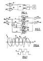
- the means for detecting the rotation of the mobile assembly consist of an opaque ring secured to the movable assembly, in which equidistant openings are provided, and means for emitting light towards reception means through said openings of the opaque ring.
- a magnetic compass according to the invention comprises a movable assembly 1 rotatably mounted in a housing 2 comprising a cover 3, the housing being suspended from the gimbal in a known manner in any support.
- magnetic means 4 constituted for example by two magnetic bars 4 a , 4 b arranged in parallel on the moving element, and conferring on the latter a unique North-South magnetic polarity.
- the magnetic compass according to the invention also comprises means for damping the rotation of said mobile assembly.
- damping means consist for example of a ring 5 of electrically conductive material, disposed on the bottom of the housing near said magnetic means 4.
- This ring 5 has a lateral annular rim 5a surrounding the magnetic means of the mobile equipment.
- the moving element 1 is mounted for rotation in the housing by means of parts in sail 6, 7 extending on either side of the moving element, the ends of these projecting parts being guided in rotation in end bearings 8, 9 respectively, integral with the housing.
- end bearings are constituted for example by flaps.
- one, 8, of the end bearings is integral with the cover 3 of the housing and the other, 9, of the bottom thereof.
- said protruding parts 6 and 7 are formed by the ends of a rod 10 forming a rotation shaft, passing through the movable assembly and emerging on either side thereof, this rod being integral with the assembly mobile.
- the compass according to the invention also comprises means for detecting the rotation of the mobile assembly 1 relative to the housing.
- detection means are constituted by an opaque ring 11 secured to the movable assembly 1 and in which are equidistant openings, as will be seen in more detail below.
- These means for detecting the rotation of the moving assembly also include light emitting means 12 intended to emit light towards light receiving means 13 through said openings of the ring 11.
- the light emission 12 and reception 13 means 13 are integral with the cover 3 of the housing and are arranged in recesses provided for this purpose therein. These transmission and reception means are connected for example to an electronic processing circuit which will be described in detail below, arranged on a printed circuit board 3 a , fixed on the cover 3 of the housing in a housing 3 b of this one.
- light reflection means constituted for example by a reflection ring 14, of generally frustoconical section, the lateral faces of which form an angle of approximately 90 °, are integral with the movable assembly and are arranged opposite the light emission and reception means.
- a reflection ring 14 is arranged opposite the light emission means 12 and the other side face of the latter is arranged opposite the openings of the opaque ring 11, as are the light receiving means 13.
- the light beam emitted by the light emitting means 12 is reflected a first time, by a first lateral face of the ring 14, towards a second face of this ring, so that the light beam is reflected a second time, towards the light receiving means 13, through the openings of the opaque ring 11.
- the means of damping the rotation of the moving assembly are based on the laws of electromagnetism of LENZ and FOUCAULT.
- the flux variations generated by the movements of the magnets integral with the moving assembly, during the displacement thereof, create in the closed electrical circuit, which constitutes the ring 5, an electric current directly proportional to the displacement speed. of the moving element, the air gap between the permanent magnets and the ring 5 being approximately constant.
- This current induced by the laws of LENZ, generates a well-known feedback from FOUCAULT on the mobile assembly, tending to oppose its displacement.
- the movement of the moving assembly is all the more damped the faster its movement speed.
- the magnetic means are constituted by magnetic bars.
- an improvement in the damping of the rotation of the moving assembly and the balancing of the latter can be obtained by using a radial field toroidal magnet.
- the light emitting means 12 are in fact constituted by two light-emitting diodes 12a, 12b and the light receiving means are constituted by two pairs 13a, 13b of photo-transistors, disposed concentrically on the housing cover.
- covers for example fixed on the inner wall of the cover 3, facing the moving element .
- covers can for example be constituted by a ring 15 (FIG. 1) or by a ring portion, in which a number of openings identical to the openings of the opaque ring 11 are formed.
- the openings of a cover of a recess of a photo-transistor 16 are offset by a distance corresponding to an odd whole number of openings, relative to the openings of the cover of the recess of the photo-transistor 17 of the same pair 13 a , so that when, for example, the openings of the cover of the recess of the photo-transistor 16, are opposite the openings 11a of the opaque ring 11 of the moving part, the openings of the cover of the recess of the phototransistor 17 are opposite solid parts of this ring 11.
- the openings of the covers of the recesses of the photo-transistors of the other pair 13 b are also offset by an odd whole number of openings.
- the openings of the covers of the recesses of the photo-transistors of this pair 13 b are offset by a distance corresponding to an odd whole number of half-openings relative to those of the covers of the recesses of the photo-transistor of the pair. 13 a .
- the photo-transistors of each pair receive opposite light signals allowing to obtain, as will be seen hereinafter, a switching of the processing circuit, at the center of one of the openings of the ring 11 of the moving assembly, whatever the lighting or positioning drifts that one can meet on the periphery of this opaque ring 11.
- the offset of an odd number of half-openings, of the openings of the covers of the pairs of photo-transistors makes it possible to obtain output signals from the pairs of photo-transistors offset between them, this offset allowing, as will be seen by thereafter, to determine the direction of rotation of the ring 11 and therefore of the movable assembly relative to the housing.
- the outputs of the photo-transistors of each pair 13a and 13b are connected to the inputs of signal shaping means 18 and 19 respectively.
- the outputs of these shaping means are connected to means 20 for detecting the direction of rotation of the moving element and the outputs of these detection means are connected to the input of counting / counting means 21 of slots appearing on the signals coming from the photo-transistors, and each corresponding as will be seen thereafter, to the passage of an opening of the ring 11 of the moving assembly, in front of one of the pairs of photo-transistors during the rotation of the latter, to increment or decrement said up / down counting means as a function of the rotation of the moving element.
- the output of the up / down counting means 21 is connected for example to display means 22.
- the signal shaping means 18 and 19 are advantageously constituted by differential amplifiers.
- the outputs of the photo-transistors of each pair being connected respectively to one or the other of the inverting or non-inverting inputs of the corresponding differential amplifier.
- the photo-transistors 16 and 17 of a first pair receive opposite light signals . Passing these signals through a differential operational amplifier makes it possible to obtain a signal A with a duty cycle equal to 1, the switching edges of which are located exactly at the intersections of the output signals of the photo-transistors of each pair.
- This offset between the appearance of the rising edges of the output signals from the pairs of photo-transistors is used to determine the direction of rotation of the ring relative to the housing.
- the means for detecting the direction of rotation of the ring 11 and therefore of the movable assembly with respect to the housing therefore consist of means for detecting the appearance of a first rising edge on the signals coming from the one or the other pairs of photo transistors.
- these means are constituted for example by a rocker circuit.
- This circuit comprises for example four flip-flops referenced respectively 23, 24, 25 and 26, the output Q / of each of these flip-flops being looped back to terminal J and terminal K being connected to ground.
- the first flip-flop 23 receives on its input CK, the signal A coming from a first pair of photo-transistors, for example 13 a through the differential amplifier 18 and on its input R the signal B coming from the other pair of photo-transistors, for example 13 b through the differential amplifier 19.
- the second flip-flop 24 receives on its input R the signal A and on its input CK the signal B.
- the flip-flop 25 receives on its input R the inverted signal A / and on its input CK the inverted signal B /, while the flip-flop 26 receives on its input R the signal B / and on its input CK the signal A /.
- the Q outputs of flip-flops 23 and 26 are connected to the inputs of an OR gate 27 and the Q outputs of flip-flops 24 and 25 are connected to the inputs of an OR gate 28.
- the CKA and CKB outputs of these gates 27 and 28 are connected for example to the incrementing and decrementing inputs of the up / down counting means 21 of slots appearing on the signals coming from the photo-transistors.
- the flip-flop circuit which has just been described, operating in a known manner, detects on which signal A or B, the first rising edge appears and increments or decrements said up / down counting means 21 according to this detection and the number of slots appearing on the signals and corresponding to a rotation of the mobile assembly relative to the housing.
- the openings of the opaque ring 11 of the movable assembly can for example be made by chemical cutting to obtain ninety openings allowing, using the processing device described, to obtain a resolution of 1 ° .
- the reflection ring 14 can be made of injected plastic material of the ABS type.
- the compass described only gives relative positions of the housing and therefore of the support on which it is arranged, with respect to the moving element.
- the electronic processing circuit is informed of the passage of the support in front of a particular point of the moving assembly and can thus calculate the new heading according to this reference taken as origin.
- This initialization can also be done using a photo-transistor receiving light at the time of the coincidence of a hole 29 ( Figure 3) formed in the opaque ring 11 of the moving assembly and a hole 30 of the ring 15 constituting the cover.
- the up / down counting means can be constituted for example by a component of the type 74 LS 192 making it possible to obtain the heading in degrees, expressed by a binary number, and receiving on its increment or decrement inputs, pulses corresponding to the rising edges of the CKA or CKB signals for output from OR gates 27 and 28.
- microprocessor for example an INTEL 8031, programmed so as to exclude valid mechanical instabilities which may exist during a vibration around a switching point, and to test the state of channels A and B and to deduce whether it is necessary to increment or decrement an internal or external counter.
- this microprocessor it is also possible to program this microprocessor so that it comes to read at a rate of for example 0.25 ms, the channels A and B, without losing any transitions, due to the relative slowness of the displacement. of the moving part with respect to the housing.
- This compass finds its application more particularly in automatic boat pilots, positioning of underwater sonar buoys, camera angle repeaters, etc.
Landscapes
- Engineering & Computer Science (AREA)
- Radar, Positioning & Navigation (AREA)
- Remote Sensing (AREA)
- Physics & Mathematics (AREA)
- General Physics & Mathematics (AREA)
- Indicating Or Recording The Presence, Absence, Or Direction Of Movement (AREA)
Applications Claiming Priority (2)
| Application Number | Priority Date | Filing Date | Title |
|---|---|---|---|
| FR8518785A FR2591738B1 (fr) | 1985-12-18 | 1985-12-18 | Compas magnetique comportant un equipage mobile et des moyens d'amortissement et de detection de la rotation de celui-ci |
| FR8518785 | 1985-12-18 |
Publications (1)
| Publication Number | Publication Date |
|---|---|
| EP0227544A2 true EP0227544A2 (de) | 1987-07-01 |
Family
ID=9325936
Family Applications (1)
| Application Number | Title | Priority Date | Filing Date |
|---|---|---|---|
| EP19860402794 Withdrawn EP0227544A2 (de) | 1985-12-18 | 1986-12-12 | Magnetkompass |
Country Status (3)
| Country | Link |
|---|---|
| EP (1) | EP0227544A2 (de) |
| AU (1) | AU6660986A (de) |
| FR (1) | FR2591738B1 (de) |
Cited By (1)
| Publication number | Priority date | Publication date | Assignee | Title |
|---|---|---|---|---|
| EP1265052A3 (de) * | 2001-06-07 | 2004-04-14 | ULTRAFLEX S.p.A. | Magnetischer Schiffskompass |
Family Cites Families (2)
| Publication number | Priority date | Publication date | Assignee | Title |
|---|---|---|---|---|
| US3888016A (en) * | 1972-08-10 | 1975-06-10 | Little Inc A | Digital compass |
| US4095348A (en) * | 1976-11-10 | 1978-06-20 | The Brunton Company | Digital compass |
-
1985
- 1985-12-18 FR FR8518785A patent/FR2591738B1/fr not_active Expired - Lifetime
-
1986
- 1986-12-12 EP EP19860402794 patent/EP0227544A2/de not_active Withdrawn
- 1986-12-16 AU AU66609/86A patent/AU6660986A/en not_active Abandoned
Cited By (1)
| Publication number | Priority date | Publication date | Assignee | Title |
|---|---|---|---|---|
| EP1265052A3 (de) * | 2001-06-07 | 2004-04-14 | ULTRAFLEX S.p.A. | Magnetischer Schiffskompass |
Also Published As
| Publication number | Publication date |
|---|---|
| FR2591738B1 (fr) | 1990-02-02 |
| FR2591738A1 (fr) | 1987-06-19 |
| AU6660986A (en) | 1987-06-25 |
Similar Documents
| Publication | Publication Date | Title |
|---|---|---|
| EP3835886B1 (de) | Armbanduhr mit steuerungsorgan | |
| FR2531481A1 (fr) | Transducteur et procede pour detecter la position angulaire du corps d'un instrument de mesure et de controle de sondage par rapport a une position de reference | |
| EP0952426A1 (de) | Uhrwerk mit einem induktiven oder kapazitiven Sensor zur Detektion von mindestens einem Drehwinkel eines Zahnrades innerhalb des Uhrwerkes | |
| US3902252A (en) | Magnetic field directional sensor | |
| EP0964226A1 (de) | Ablesevorrichtung für hochauflösenden optischen Kodierer | |
| EP0227544A2 (de) | Magnetkompass | |
| FR2544187A3 (fr) | Dispositif doseur d'eau a rotor pour machines a cafe " express " | |
| JPS5811808A (ja) | 方位検出表示回路 | |
| EP3312565B1 (de) | Positionssensor | |
| FR2593290A1 (fr) | Detecteur de vitesse et de sens de rotation pour machine tournante | |
| FR2743882A1 (fr) | Dispositif et procede de reperage de position d'un element mobile, en particulier pour un instrument de mesure | |
| CH678359A5 (en) | Earth's magnetic field measurement device - uses excitation and monitoring coils with rotating magnetic arm for accurate direction finder | |
| EP0148046B1 (de) | Detektor, der in einer aggressiven Umwelt funktionieren kann | |
| EP0170576B1 (de) | Regelvorrichtungen von Messgebern von Drehwinkelpositionsmesseinrichtungen | |
| SU1601586A1 (ru) | Измеритель скорости | |
| FR2765965A1 (fr) | Micromecanisme optoelectronique de controle de niveau | |
| FR2496256A1 (fr) | Compas magnetique optoelectrique | |
| EP0158557A1 (de) | Vorrichtung zur Unterdrückung von Vibrationsgeräuschen in einem Laserkreisel und Anwendung dieser Vorrichtung | |
| WO1982002088A1 (fr) | Compas magnetique opto-electrique | |
| FR2467387A1 (fr) | Capteur numerique de la direction horizontale du champ magnetique terrestre | |
| FR2644240A1 (fr) | Capteur inductif de position angulaire | |
| JPS6219923Y2 (de) | ||
| SU468089A1 (ru) | Датчик углового положени ротора гироскопа | |
| EP0223676A1 (de) | Rotierende Laufwerkanlage für mindestens eine magnetische Platte und elektrischer Motor in dieser Anlage einbegriffen | |
| FR2528173A1 (fr) | Cassette de mesure du couple de rotation sur les arbres de mandrins d'appareils a cassette |
Legal Events
| Date | Code | Title | Description |
|---|---|---|---|
| PUAI | Public reference made under article 153(3) epc to a published international application that has entered the european phase |
Free format text: ORIGINAL CODE: 0009012 |
|
| AK | Designated contracting states |
Kind code of ref document: A2 Designated state(s): DE GB IT NL SE |
|
| STAA | Information on the status of an ep patent application or granted ep patent |
Free format text: STATUS: THE APPLICATION HAS BEEN WITHDRAWN |
|
| 18W | Application withdrawn |
Withdrawal date: 19870924 |
|
| RIN1 | Information on inventor provided before grant (corrected) |
Inventor name: LOGEAY, FRANCOIS |