EP0227500B1 - Position-adjusting device for a belt anchor, in particular for a motor vehicle seat belt - Google Patents
Position-adjusting device for a belt anchor, in particular for a motor vehicle seat belt Download PDFInfo
- Publication number
- EP0227500B1 EP0227500B1 EP86402339A EP86402339A EP0227500B1 EP 0227500 B1 EP0227500 B1 EP 0227500B1 EP 86402339 A EP86402339 A EP 86402339A EP 86402339 A EP86402339 A EP 86402339A EP 0227500 B1 EP0227500 B1 EP 0227500B1
- Authority
- EP
- European Patent Office
- Prior art keywords
- electric motor
- motor
- tube
- conductive tracks
- return element
- Prior art date
- Legal status (The legal status is an assumption and is not a legal conclusion. Google has not performed a legal analysis and makes no representation as to the accuracy of the status listed.)
- Expired
Links
Images


Classifications
-
- B—PERFORMING OPERATIONS; TRANSPORTING
- B60—VEHICLES IN GENERAL
- B60R—VEHICLES, VEHICLE FITTINGS, OR VEHICLE PARTS, NOT OTHERWISE PROVIDED FOR
- B60R22/00—Safety belts or body harnesses in vehicles
- B60R22/18—Anchoring devices
- B60R22/20—Anchoring devices adjustable in position, e.g. in height
- B60R22/201—Anchoring devices adjustable in position, e.g. in height with the belt anchor connected to a slider movable in a vehicle-mounted track
-
- B—PERFORMING OPERATIONS; TRANSPORTING
- B60—VEHICLES IN GENERAL
- B60R—VEHICLES, VEHICLE FITTINGS, OR VEHICLE PARTS, NOT OTHERWISE PROVIDED FOR
- B60R22/00—Safety belts or body harnesses in vehicles
- B60R22/18—Anchoring devices
- B60R22/20—Anchoring devices adjustable in position, e.g. in height
- B60R2022/208—Anchoring devices adjustable in position, e.g. in height by automatic or remote control means
-
- Y—GENERAL TAGGING OF NEW TECHNOLOGICAL DEVELOPMENTS; GENERAL TAGGING OF CROSS-SECTIONAL TECHNOLOGIES SPANNING OVER SEVERAL SECTIONS OF THE IPC; TECHNICAL SUBJECTS COVERED BY FORMER USPC CROSS-REFERENCE ART COLLECTIONS [XRACs] AND DIGESTS
- Y10—TECHNICAL SUBJECTS COVERED BY FORMER USPC
- Y10T—TECHNICAL SUBJECTS COVERED BY FORMER US CLASSIFICATION
- Y10T74/00—Machine element or mechanism
- Y10T74/18—Mechanical movements
- Y10T74/18568—Reciprocating or oscillating to or from alternating rotary
- Y10T74/18576—Reciprocating or oscillating to or from alternating rotary including screw and nut
- Y10T74/18656—Carriage surrounded, guided, and primarily supported by member other than screw [e.g., linear guide, etc.]
Definitions
- the other end of the armature 15 has a manifold 25 allowing the supply of the electric motor.
- the supply means 25a of this collector will be described in more detail below.
- the cursor 111 causes a displacement of the drawer 101 which is for example in the form of an insulating plate, in a slide 112 of any support structure integral with the vehicle .
- This support structure comprises a slot 113 through which protrudes a part of the drawer 101 on which the slider 11 is fixed.
- the conductive tracks of the set 106 are for example arranged in housings 114 and 115 formed for this purpose in the structure of support.
Description
La présente invention concerne un dispositif de réglage de la position d'un renvoi de sangle notamment de ceinture de sécurité pour véhicule automobile.The present invention relates to a device for adjusting the position of a strap return, in particular a seat belt for a motor vehicle.
Sur la plupart des véhicules, ce renvoi de sangle est disposé sur un doigt d'ancrage fixé sur la carrosserie du véhicule, à une hauteur convenant à une majorité d'utilisateurs dits de taille normale.On most vehicles, this strap return is placed on an anchoring finger fixed to the vehicle body, at a height suitable for a majority of so-called normal-sized users.
Toutefois, cette hauteur ne convient pas à certains utilisateurs, en particulier aux personnes de petite taille.However, this height is not suitable for some users, especially short people.
Pour résoudre ce problème, on connait dans l'état de la technique un certain nombre de dispositifs mécaniques de réglage de la hauteur de ce renvoi de sangle.To solve this problem, a number of mechanical devices for adjusting the height of this strap return are known in the prior art.
Le EP-A 0 092 105 décrit un dispositif de réglage de la position d'un renvoi de sangle de ceinture, ce dispositif étant muni d'un moteur électrique que fait tourner un arbre fileté. Le renvoi de sangle est monté sur une pièce taraudée qui coopère avec l'arbre fileté.EP-A 0 092 105 describes a device for adjusting the position of a belt strap return, this device being provided with an electric motor which rotates a threaded shaft. The strap return is mounted on a threaded part which cooperates with the threaded shaft.
Cependant, ces dispositifs présentent un certain nombre d'inconvénients, notamment au niveau des possibilités de réglage, de leur structure relativement complexe et donc de leurs coûts de fabrication et de montage relativement élevés.However, these devices have a certain number of drawbacks, particularly in terms of adjustment possibilities, their relatively complex structure and therefore their relatively high manufacturing and mounting costs.
Le but de l'invention est de résoudre les problèmes évoqués ci-dessus en proposant un dispositif de réglage, rapide et précis, de la position du renvoi de sangle, pour adapter celle-ci à la morphologie de l'utilisateur.The object of the invention is to solve the problems mentioned above by proposing a device for adjusting, quickly and precisely, the position of the strap return, to adapt it to the morphology of the user.
A cet effet, l'invention a pour objet un dispositif de réglage de la position d'un renvoi de sangle notamment de ceinture de sécurité pour véhicule automobile, dans lequel le renvoi de sangle est monté déplaçable entre deux positions extrêmes par l'intermédiaire de moyens d'entraînement comportant un moteur électrique alimenté par l'intermédiaire d'un organe de commande de la position dudit renvoi, en tout point de la course de celui-ci, définie par les deux positions extrêmes, le renvoi de sangle étant disposé sur un doigt d'ancrage, caractérisé en ce que le doigt d'ancrage est solidaire du moteur électrique, ledit moteur électrique étant monté déplaçable axialement entre lesdites deux positions extrêmes, dans un tube et en ce qu'il est prévu des moyens d'immobilisation en rotation de l'induit du moteur électrique, l'inducteur de celui-ci étant monté à rotation autour de l'induit, en ce qu'au moins une partie de la surface extérieure de l'inducteur du moteur présente un filetage coopérant avec des moyens complémentaires solidaires du tube de manière à assurer le déplacement du moteur et donc du renvoi de sangle lors de la rotation de l'inducteur, et en ce que les moyens d'immobilisatin en rotation de l'induit sont constitués par le doigt d'ancrage du renvoi de sangle, l'une des extrémités de ce doigt faisant saillie à l'intérieur du tube à travers und fente ménagée dans celui-ci, cette extrémité du doigt d'ancrage étant reliée à l'une des extrémités de l'arbre de l'induit du moteur électrique par des moyens de fixation.To this end, the subject of the invention is a device for adjusting the position of a strap return, in particular of a seat belt for a motor vehicle, in which the strap return is mounted movable between two extreme positions by means of drive means comprising an electric motor powered by a control member for the position of said gear, at any point in the travel thereof, defined by the two extreme positions, the strap gear being disposed on an anchoring finger, characterized in that the anchoring finger is integral with the electric motor, said electric motor being mounted axially displaceable between said two extreme positions, in a tube and in that immobilization means are provided in rotation of the armature of the electric motor, the inductor of the latter being rotatably mounted around the armature, in that at least a part of the external surface of the inductor of the motor has a cooperated thread rant with complementary means integral with the tube so as to ensure the displacement of the motor and therefore of the belt return during the rotation of the inductor, and in that the immobilizing means in rotation of the armature are constituted by the anchor finger of the strap return, one end of this finger projecting inside the tube through a slot formed therein, this end of the anchor finger being connected to one end of the armature shaft of the electric motor by fixing means.
L'invention sera mieux comprise à l'aide de la description qui va suivre, donnée uniquement à titre d'exemple et faite en se référant aux dessins annexés, sur lesquels:
- - la Fig. 1 représente une vue d'un habitacle d'un véhicule automobile équipé d'un dispositif de réglage selon l'invention;
- - la Fig. 2 représente une vue en perspective avec des parties coupées d'un dispositif de réglage selon l'invention;
- - la Fig. 3 représente une vue en coupe d'un dispositif de réglage selon l'invention;
- - les Fig. 4 et 5 représentent des vues à échelle agrandie de moyens de liaison entrant dans la constitution d'un dispositif selon l'invention;
- - la Fig.6 représente un premier mode de réalisation des moyens d'alimentation entrant dans la constitution d'un dispositif selon l'invention ;
- - la Fig. 7 représente une vue en coupe d'une variante de réalisation d'un dispositif de réglage selon l'invention;
- - la Fig.8 représente un second mode de réalisation des moyens d'alimentation entrant dans la constitution d'un dispositif de l'invention;
- - la Fig.9 représente une vue en coupe à échelle agrandie suivant la ligne IX-IX de la Fig.8; et
- - les Fig.10 et 11 représentent un troisième mode de réalisation des moyens d'alimentation entrant dans la constitution d'un dispositif selon l'invention.
- - Fig. 1 shows a view of a passenger compartment of a motor vehicle equipped with an adjustment device according to the invention;
- - Fig. 2 shows a perspective view with cut parts of an adjustment device according to the invention;
- - Fig. 3 shows a sectional view of an adjustment device according to the invention;
- - Figs. 4 and 5 show views on an enlarged scale of connecting means forming part of a device according to the invention;
- - Fig.6 shows a first embodiment of the supply means forming part of a device according to the invention;
- - Fig. 7 shows a sectional view of an alternative embodiment of an adjustment device according to the invention;
- - Fig.8 shows a second embodiment of the supply means forming part of a device of the invention;
- - Fig.9 shows a sectional view on an enlarged scale along line IX-IX of Fig.8; and
- - Fig.10 and 11 show a third embodiment of the supply means forming part of a device according to the invention.
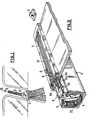
Comme on peut le voir sur la Fig.1, un renvoi de sangle 1 est monté déplaçable suivant un axe X-X entre deux positions extrêmes, sur un montant vertical d'un véhicule automobile. Un organe 2 de commande de la position de ce renvoi de sangle, qui sera décrit par la suite, est disposé par exemple au-dessus d'une fente 3 dans laquelle se déplace un doigt d'ancrage 4 du renvoi de sangle 1.As can be seen in Fig.1, a strap return 1 is mounted movable along an axis X-X between two extreme positions, on a vertical post of a motor vehicle. A member 2 for controlling the position of this strap return, which will be described hereinafter, is arranged for example above a slot 3 in which moves an anchoring
Le doigt d'ancrage 4 (Fig.2) est solidaire d'un moteur électrique 5 monté déplaçable axialement entre les deux positions extrêmes dans un tube 6 taraudé intérieurement fixé sur la carrosserie du véhicule. Ce tube présente dans sa partie supérieure, une fente 7 à travers laquelle font saillie le doigt d'ancrage 4 et une partie 8 de moyens d'alimentation de ce moteur électrique qui seront décrits plus en détail par la suite.The anchoring finger 4 (FIG. 2) is integral with an
Un organe de support 9 isolant, fixé sur le tube 6, comporte une fente 10 ménagée en regard de la fente 7 du tube et des moyens déformables 11 de fermeture de cette fente 10. Le doigt d'ancrage 4 peut donc se déplacer avec le moteur entre les deux positions extrêmes de cette fente en déformant les moyens déformables 11 sur son passage, ces moyens reprenant leur position initiale après le passage de celui-ci, pour fermer cette fente. Ainsi, aucune poussière et aucun corps étranger ne peuvent s'introduire dans le mécanisme du dispositif selon l'invention.An
Comme il est représenté sur la Fig.3, le doigt d'ancrage 4 sur lequel est disposé le renvoi de sangle 1 comporte une extrémité qui fait saillie dans le tube 6 à travers la fente 7. Cette extrémité du doigt d'ancrage est par exemple vissée dans une pièce de liaison 12. Une entretoise 13 est disposée autour du doigt d'ancrage 4, entre cette pièce de liaison 12 et le renvoi de sangle 1, cette entretoise coopérant avec les rebords de la fente 7 du tube pour guider le doigt d'ancrage lors de son déplacement. Cette entretoise permet également de maintenir le renvoi de sangle à une distance prédéterminée de la pièce de liaison.As shown in Fig.3, the
D'autre part, cette pièce de liaison 12 coopére avec les surfaces intérieures des rebords de la fente 7 du tube pour retenir le doigt d'ancrage en position.On the other hand, this connecting
Cette pièce de liaison 12 est fixée sur une extrémité d'un arbre 14 d'un induit 15 du moteur électrique 5 par l'intermédiaire d'une lame métallique 16 dont l'une des extrémités présente un évidement 17 engagé sur l'extrémite correspondante de l'arbre de l'induit et dont l'autre extrémité présente deux ai lettes 18 et 19 qui comme on le verra par la suite comportent des décrochements dans lesquels sont engagés des bossages de la pièce de liaison 12 pour entraîner cette pièce de liaison et donc le renvoi de sangle lorsque le moteur électrique se déplace à l'intérieur du tube.This connecting
Le moteur électrique 5 comporte également un inducteur 20 monté à rotation par l'intermédiaire de paliers 20a et 20b autour de l'induit 15 et dont au moins une partie de la surface extérieure présente un filetage 21 coopérant avec un taraudage 22 formé dans la surface intérieure du tube 6.The
Il est à noter que le doigt d'ancrage 4 étant solidaire de l'induit 15 du moteur électrique, cet induit est immobilisé en rotation. En effet, le doigt d'ancrage étant relié à l'arbre de l'induit et traversant la fente 7 du tube 6, il coopére avec les rebords de celle-ci pour empêcher toute rotation de l'induit.It should be noted that the anchoring
Dans ce cas, lorsque le moteur électrique est alimenté, c'est l'inducteur 20 qui tourne autour de l'induit, de sorte que le filetage extérieur 21 de celui-ci coopère avec le taraudage intérieur 22 du tube pour assurer le déplacement de l'ensemble.In this case, when the electric motor is supplied, it is the
Il est également à noter que la surface de la pièce de liaison 12, disposée en regard d'une surface correspondante de l'inducteur 20, présente des moyens anti-friction de manière à limiter les frottements à ce niveau entre les deux pièces.It should also be noted that the surface of the connecting
Ainsi par exemple, les moyens anti-friction sont constitués par une bille 23 disposée dans un logement 24 ménagé à cet effet dans la pièce de liaison 12.Thus, for example, the anti-friction means consist of a
Comme on le voit sur cette figure, l'autre extrémité de l'induit 15 présente un collecteur 25 permettant l'alimentation du moteur électrique. Les moyens d'alimentation 25a de ce collecteur, seront décrits plus en détail par la suite.As can be seen in this figure, the other end of the
Sur les Fig.4 et 5, on a représenté plus en détail les moyens de fixation du doigt d'ancrage sur l'arbre de l'induit du moteur. Ainsi par exemple, la lame métallique 16 présente à l'une de ses extrémités l'évidement 17 destiné à être engagé sur l'extrémité correspondante dudit arbre. A son autre extrémité, cette lame métallique comporte les deux ailettes 18 et 19 présentant des décrochements 26 et 27 respectivement dans lesquels sont engagés des bossages 28 et 29 respectivement (Fig.5) de la pièce de liaison 12. Ainsi qu'il a déjà été mentionné, ces ailettes permettent de déplacer la pièce de liaison lorsque le moteur électrique se déplace à l'intérieur du tube de façon à transmettre ce déplacement au doigt d'ancrage 4 par l'intermédiaire de la pièce de liaison 12 et donc de déplacer le renvoi de sangle 1.In Fig.4 and 5, there is shown in more detail the means for fixing the anchoring finger on the armature shaft of the motor. Thus, for example, the
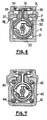
Comme il est représenté sur la Fig. 6,l'alimentation du collecteur 25 du moteur peut être assurée par un premier jeu 30 de frotteurs reliés au collecteur du moteur électrique, ces frotteurs étant en contact avec un premier jeu 31 de pistes conductrices disposées axialement sur la surface intérieure d'une bague 32 solidaire de l'induit du moteur, ces pistes conductrices étant reliées, par l'intermédiaire d'un second jeu 33 de frotteurs, à un second jeu 34 de pistes conductrices disposées de part et d'autre de la fente 7 du tube 6, et plus particulièrement le long de la fente 10 de l'organe de support 9, ce second jeu de pistes conductrices étant relié à la source d'alimentation du véhicule par l'intermédiaire de l'organe de commande 2 de la position du renvoi.As shown in FIG. 6, the
Cet organe de commande est constitué par exemple par un inverseur à trois positions permettant de connecter les pistes du second jeu 34 de pistes conductrices à la source d'alimentation, de manière que le moteur électrique et donc le renvoi de sangle se déplacent soit dans un sens, soit dans l'autre, suivant la polarité du jeu 34 de pistes, vers une position désirée et de couper cette alimentation lorsque cette position est atteinte pour immobiliser le moteur et déterminer ainsi une nouvelle position du renvoi de sangle.This control member is constituted for example by a three-position inverter making it possible to connect the tracks of the
Les pistes du second jeu 34 de pistes sont disposées de part et d'autre de la fente 10 de l'organe de support 9 dans des logements 35 ménagés à cet effet dans l'organe de support 9 fixé sur le tube 6 par l'intermédiaire de pattes de fixation 36 comportant des parties en saillie 37 coopérant avec des évidements ménagés à cet effet dans les parois latérales du tube.The tracks of the
Le jeu 33 de frotteurs se déplaçant avec le moteur lorsque celui-ci est alimenté, il est toujours en contact avec le jeu de pistes 34 de sorte que l'alimentation du moteur est assurée tant que l'inverseur n'est pas en position de repos. Ainsi l'organe de commande 2 de la position du renvoi de sangle permet d'obtenir un positionnement du renvoi de sangle en tout point de la course de celui-ci définie par les deux positions extrêmes.The
Selon une variante de réalisation représentée sur la Fig. 7, le moteur électrique est monté déplaçable à l'intérieur d'un tube 40 par exemple, de section, carrée, l'inducteur de ce moteur comportant un filetage extérieur coopérant par exemple avec qua tre tiges filetées, 41 à 44, fixées dans les quatre angles dudit tube, respectivement, de manière à assurer le déplacement du moteur et donc du renvoi de sangle lors de la rotation de l'inducteur.According to an alternative embodiment shown in FIG. 7, the electric motor is mounted movable inside a
Il va de soi que trois tiges filetées, par exemple disposées à 120° l'une de l'autre, peuvent être suffisantes pour permettre le déplacement du moteur à l'intérieur du tube. Le tube peut également présenter une section autre que carrée.It goes without saying that three threaded rods, for example arranged at 120 ° from one another, may be sufficient to allow the movement of the motor inside the tube. The tube may also have a section other than square.
Les autres éléments et le fonctionnement de ce mode de réalisation étant identiques à ceux du mode de réalisation précédent, on ne les décrira pas plus en détail.The other elements and the operation of this embodiment being identical to those of the previous embodiment, they will not be described further. in detail.
Comme cela a été décrit précédemment, les moyens d'alimentation du moteur électrique, entrant dans la constitution d'un dispositif selon l'invention, comportent un premier jeu de frotteurs reliés au collecteur du moteur électrique, ces frotteurs étant en contact avec un premier jeu de pistes conductrices disposées axialement sur la surface intérieure d'une bague solidaire de l'induit du moteur.As described above, the means for supplying the electric motor, forming part of a device according to the invention, comprise a first set of wipers connected to the collector of the electric motor, these wipers being in contact with a first set of conductive tracks arranged axially on the inner surface of a ring secured to the armature of the motor.
Les éléments des moyens de commande qui seront décrits par la suite, constituent donc les moyens permettant de relier ces pistes conductrices de la bague à la source d'alimentation du véhicule.The elements of the control means which will be described later, therefore constitute the means making it possible to connect these conductive tracks of the ring to the power source of the vehicle.
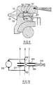
Selon le mode de réalisation représenté sur les Fig.8 et 9, l'organe de commande de la position du renvoi de sangle, comprend un tiroir 101 sur lequel est disposé un premier jeu 102 de trois pistes conductrices respectivement 103,104 et 105 à peu près alignées, séparées l'une de l'autre par un espace libre de coupure de l'alimentation du moteur électrique et connectées à la source d'alimentation du véhicule de manière à présenter des polarités alternées successi vement. Ces pistes conductrices . sont reliées à un second jeu 106 de pistes conductrices reliées aux bornes positive et négative de la source d'alimentation du véhicule, par l'intermédiaire de frotteurs, par exemple 107 pour la piste conductrice 105. Ainsi, dans l'exemple décrit, les pistes conductrices 103 et 105 présentent une polarité positive, tandis que la piste 104 présente une polarité négative.According to the embodiment shown in FIGS. 8 and 9, the control member for the position of the strap return comprises a
Le moteur électrique 108 de déplacement du renvoi de sangle comporte deux frotteurs 109 et 110 reliant les pistes de la bague au reste de l'organe de commande et qui, comme il est représenté sur la Fig.8, sont en regard des espaces libres séparant les pistes conductrices l'une de l'autre. Ces frotteurs 109 et 110 sont destinés à coopérer avec les pistes conductrices 103,104 pour alimenter le moteur pour qu'il se déplace dans une certaine direction ou avec les pistes conductrices 104,105 pour alimenter celui-ci afin qu'il se déplace dans l'autre direction. Cette commande du moteur est fonction du déplacement du tiroir 101 par rapport aux frotteurs 109 et 110 d'alimentation du moteur. En effet, un curseur 111, solidaire du tiroir, est monté déplaçable manuellement le long de la course de réglage du renvoi de sangle, pour régler la position du tiroir 101 et donc des espaces libres de coupure de l'alimentation du moteur et déterminer ainsi sa position et donc celle du renvoi de sangle. En fonction du déplacement du curseur et donc du tiroir, le moteur électrique est alimenté soit dans un sens soit dans l'autre jusqu'à ce qu'il arrive dans la position de réglage désiré dans laquelle les curseurs 109 et 110 sont en regard des espaces libres de coupure de l'alimentation du moteur.The
Comme on peut le voir plus clairement sur la Fig.9, le curseur 111 entraîne un déplacement du tiroir 101 qui se présente par exemple sous la forme d'une plaquette isolante, dans une glissière 112 d'une structure de support quelconque solidaire du véhicule. Cette structure de support comporte une fente 113 à travers laquelle fait saillie une partie du tiroir 101 sur laquelle est fixé le curseur 111. Les pistes conductrices du jeu 106 sont par exemple disposées dans des logements 114 et 115 ménagés à cet effet dans la structure de support.As can be seen more clearly in FIG. 9, the
Par ailleurs, pour des raisons de compréhension du fonctionnement du dispositif, on a représenté le frotteur 110 du moteur en appui sur la piste conductrice 105.Furthermore, for reasons of understanding the operation of the device, the
Ainsi qu'il a été décrit précédemment, le renvoi de sangle est solidaire du stator du moteur électrique et celui-ci est monté déplaçable axialement entre les deux positions extrêmes de sorte que le réglage de la position du curseur et donc des espaces libres de coupure de l'alimentation du moteur, permet d'obtenir un réglage de la position du renvoi de sangle.As described above, the strap return is integral with the stator of the electric motor and the latter is mounted axially displaceable between the two extreme positions so that the adjustment of the position of the cursor and therefore of the clearing spaces of the motor supply, allows adjustment of the position of the belt return.
Il est à noter que dans l'exemple de réalisation décrit, les frotteurs reliant le premier jeu 102 de pistes conductrices au second jeu 106, par'exemple, le frotteur 107 pour la piste 105, traversent la plaquette isolante constituant le tiroir.It should be noted that in the embodiment described, the wipers connecting the
Les autres composants de ce dispositif étant 'identiques à ceux décrits précédemment, on ne les décrira pas plus en détail.The other components of this device are identical to those described above, will not be described in more detail.
L'organe de commande 120 (Fig. 10) peut également comporter un tiroir 121 monté déplaçable à coulissement dans une glissière 122 par l'intermédiaire d'un curseur 123 faisant saillie hors de la glis sière par une fente 122a ménagée à cet effet dans celle-ci, de sorte que l'utilisateur a accès à ce curseur pour déplacer manuellement le tiroir. Le tiroir 121 présente sur sa surface en regard du jeu de trotteurs reliant les pistes de la bague au reste de l'organe, des pistes conductrices 124 destinées à coopérer avec lesdits frotteurs pour alimenter le moteur électrique. Ces pistes conductrices sont reliées à la source d'alimentation du véhicule par exemple par des fils conducteurs 125.The control member 120 (FIG. 10) may also include a
Comme on peut le voir sur la Fig. 11, le tiroir comporte deux jeux de pistes conductrices 126 et 127 connectés à la source d'alimentation du véhicule de manière à présenter des polarités inverses. Par ailleurs, les deux jeux de pistes sont séparés par un espace libre dans lequel les frotteurs d'alimentation du moteur 128 ne sont plus en contact avec les pistes conductrices, de sorte que l'alimentation du moteur électrique est coupée.As can be seen in Fig. 11, the drawer comprises two sets of
Le fonctionnement d'un tel dispositif est le suivant.The operation of such a device is as follows.
La position de repos du dispositif est celle référencée par A sur cette Fig.11, c'est à dire celle dans laquelle les frotteurs 129, 130 du moteur 128 sont en regard de l'espace libre séparant les deux jeux de pistes conductrices. Dans ce cas, le moteur n'est pas alimenté et le doigt d'ancrage et donc le renvoi de sangle sont dans une position déterminée.The rest position of the device is that referenced by A in this Fig. 11, that is to say that in which the
Si l'on désire déplacer ce doigt d'ancrage soit vers le haut, soit vers le bas, on agit manuellement sur le curseur 123 pour déplacer le tiroir 121 dans la glissière 122 et donc les pistes conductrices 124 par rapport aux frotteurs 129,130 du moteur. On arrive alors par exemple dans la position référencée par B sur cette Fig.11, dans laquelle les frotteurs sont en contact avec le jeu 127 de pistes conductrices, de sorte que le moteur électrique 128 se déplace dans une certaine direction.If you want to move this anchor finger either up or down, you manually act on the
Le moteur se déplaçant, le doigt d'ancrage du renvoi de sangle et les frotteurs se déplacent alors également jusqu'à que les frotteurs arrivent à nouveau en regard de l'espace libre séparant les deux jeux de pistes conductrices.With the motor moving, the anchor finger of the strap return and the wipers then also move until the wipers again arrive opposite the free space separating the two sets of conductive tracks.
L'alimentation du moteur est alors coupée et celui-ci s'immobilise en déterminant une nouvelle position du doigt d'ancrage du renvoi de sangle, en fonction du déplacement du curseur.The power supply to the engine is then cut off and the latter comes to a standstill by determining a new position for the anchoring finger of the strap return, as a function of the movement of the cursor.
Dans le cas où l'on déplace le tiroir en sens inverse de celui mentionné précédemment, les frotteurs viennent en contact avec le jeu 126 de pistes conductrices comme représenté en C sur la Fig.11.In the case where the slide is moved in the opposite direction to that mentioned above, the wipers come into contact with the
La polarité de ce jeu étant inverse à celle du jeu 127, le moteur électrique est donc alimenté en sens inverse et celui-ci se déplace alors en sens inverse de celui du cas précédent.The polarity of this clearance being opposite to that of the
Le moteur se déplace dans l'autre direction tant que les frotteurs d'alimentation de celui-ci ne sont pas revenus en regard de l'espace libre séparant les deux jeux de pistes.The motor moves in the other direction as long as the feed scrapers of the latter have not returned opposite the free space separating the two sets of tracks.
Il va de soi que le renvoi de sangle étant disposé sur un doigt d'ancrage solidaire de ce moteur, il suit également ce mouvement ce qui permet de régler sa position.It goes without saying that the strap return being disposed on an anchoring finger integral with this motor, it also follows this movement which makes it possible to adjust its position.
Claims (17)
Applications Claiming Priority (4)
| Application Number | Priority Date | Filing Date | Title |
|---|---|---|---|
| FR8515831A FR2589114B1 (en) | 1985-10-24 | 1985-10-24 | IMPROVED ADJUSTMENT DEVICE FOR THE POSITION OF A STRAP RETURN, ESPECIALLY A SEAT BELT FOR A MOTOR VEHICLE |
| FR8515831 | 1985-10-24 | ||
| FR8601717A FR2594081B2 (en) | 1986-02-07 | 1986-02-07 | IMPROVED DEVICE FOR ADJUSTING THE POSITION OF A STRAP RETURN, ESPECIALLY A SEAT BELT |
| FR8601717 | 1986-02-07 |
Publications (2)
| Publication Number | Publication Date |
|---|---|
| EP0227500A1 EP0227500A1 (en) | 1987-07-01 |
| EP0227500B1 true EP0227500B1 (en) | 1989-05-24 |
Family
ID=26224783
Family Applications (1)
| Application Number | Title | Priority Date | Filing Date |
|---|---|---|---|
| EP86402339A Expired EP0227500B1 (en) | 1985-10-24 | 1986-10-17 | Position-adjusting device for a belt anchor, in particular for a motor vehicle seat belt |
Country Status (5)
| Country | Link |
|---|---|
| US (1) | US4702493A (en) |
| EP (1) | EP0227500B1 (en) |
| JP (1) | JPS62101568A (en) |
| DE (1) | DE3663494D1 (en) |
| ES (1) | ES2009795B3 (en) |
Families Citing this family (11)
| Publication number | Priority date | Publication date | Assignee | Title |
|---|---|---|---|---|
| US4765651A (en) * | 1986-05-13 | 1988-08-23 | American Safety Equipment Corporation | Adjustable anchoring slide block assembly |
| DE8717539U1 (en) * | 1987-05-26 | 1989-01-26 | Autoflug Gmbh & Co Fahrzeugtechnik, 2084 Rellingen, De | |
| DE3742390A1 (en) * | 1987-12-14 | 1989-07-27 | Autoliv Gmbh | DEVICE FOR ADJUSTING A BELT FOLDING FITTING FOR A SAFETY BELT |
| JPH0290171U (en) * | 1988-12-28 | 1990-07-17 | ||
| US5544917A (en) * | 1995-07-13 | 1996-08-13 | Trw Vehicle Safety Systems Inc. | Seat belt webbing guide assembly |
| JP2000088070A (en) * | 1998-09-09 | 2000-03-28 | Smc Corp | Motor-driven actuator |
| JP3665233B2 (en) * | 1999-08-02 | 2005-06-29 | 株式会社東海理化電機製作所 | Shock absorber and shoulder anchor height adjusting device |
| DE10011906C1 (en) * | 2000-03-11 | 2001-08-09 | Porsche Ag | Device for a belt height adjuster of a seat belt system |
| US6997479B2 (en) * | 2004-02-03 | 2006-02-14 | Key Safety Systems, Inc. | Magnetic adjustable turning loop |
| US20130127230A1 (en) * | 2011-11-21 | 2013-05-23 | Anthony Fini | Vehicle shoulder belt extension |
| US8991866B2 (en) * | 2013-06-17 | 2015-03-31 | Nissan North America, Inc. | Vehicle pillar trim assembly |
Family Cites Families (5)
| Publication number | Priority date | Publication date | Assignee | Title |
|---|---|---|---|---|
| GB1366911A (en) * | 1970-09-09 | 1974-09-18 | Lindblad O L | Safety belt arrangement for passengers in vehicles |
| DE7523101U (en) * | 1975-07-19 | 1976-02-19 | Jesus Margarido, Armindo De, 2000 Hamburg | Holding device for the upper fastening element of vehicle seat belts |
| US4564219A (en) * | 1981-10-03 | 1986-01-14 | Autoflug Gmbh | Apparatus for adjusting the height of the upper fitting for the shoulder belt in a safety belt system |
| DE3214712C2 (en) * | 1982-04-21 | 1986-10-16 | Bayerische Motoren Werke AG, 8000 München | Adjustment device for a point of attachment or deflection of a seat belt |
| GB8325844D0 (en) * | 1983-09-27 | 1983-10-26 | Kangol Magnet Ltd | Vehicle seat belt system |
-
1986
- 1986-10-17 DE DE8686402339T patent/DE3663494D1/en not_active Expired
- 1986-10-17 ES ES86402339T patent/ES2009795B3/en not_active Expired
- 1986-10-17 EP EP86402339A patent/EP0227500B1/en not_active Expired
- 1986-10-23 US US06/922,508 patent/US4702493A/en not_active Expired - Fee Related
- 1986-10-24 JP JP61253526A patent/JPS62101568A/en active Granted
Also Published As
| Publication number | Publication date |
|---|---|
| US4702493A (en) | 1987-10-27 |
| ES2009795B3 (en) | 1989-10-16 |
| JPS62101568A (en) | 1987-05-12 |
| EP0227500A1 (en) | 1987-07-01 |
| JPH0587414B2 (en) | 1993-12-16 |
| DE3663494D1 (en) | 1989-06-29 |
Similar Documents
| Publication | Publication Date | Title |
|---|---|---|
| EP0227500B1 (en) | Position-adjusting device for a belt anchor, in particular for a motor vehicle seat belt | |
| EP0458702B1 (en) | Control device, in particular for the direction of a vehicle headlamp beam | |
| EP0223672B1 (en) | Position-adjusting device for a belt anchor, in particular for a motor vehicle seat belt | |
| EP0591029B1 (en) | Adjustable steering column assembly for a motor vehicle | |
| WO1996021386A1 (en) | Electric toaster | |
| EP0669220A1 (en) | Device for longitudinally positioning a vehicle seat | |
| EP1437260B1 (en) | Rear-view vehicle mirror pivotable on two axes | |
| EP0164479B1 (en) | Connecting assembly for joining two profile members together | |
| FR2813719A1 (en) | Electric motor with brush carrier plate includes latching mechanism holding brush springs retracted until motor is assembled | |
| EP3217415B1 (en) | Wheel for a vehicle window wiper drive system | |
| EP0248716A1 (en) | Switching device for motor vehicles | |
| FR2589114A1 (en) | Device for the improved adjustment of the position of a strap return, especially a seat belt for a motor vehicle | |
| FR2769037A1 (en) | LOCKING DEVICE COMPRISING A CAM-CONTROLLED TRANSMISSION FINGER | |
| EP0008247B1 (en) | Electric window-raising device | |
| EP0866483B1 (en) | Bistable battery switch with mechanical interlock | |
| EP0102263B1 (en) | Electric lock for a vehicle door | |
| FR2580716A1 (en) | ELECTRO-MECHANICAL ACTUATOR WITH ELECTRIC MOTOR CONTROL BY HALF-TURN | |
| FR2589113A1 (en) | Device for adjusting the position of a strap return, especially for a seat belt for a motor vehicle | |
| FR2718088A1 (en) | Electric switch for supplying direction change indicators of a motor vehicle. | |
| EP0113603A1 (en) | Electrically powered vehicle window opening device | |
| EP0797230B1 (en) | Remote control with geared motor unit with a centrifugal clutch | |
| FR2594256A1 (en) | Circuit cut-out device in particular for motor vehicle | |
| FR2676383A1 (en) | DEVICE FOR LAYING AN ADAPTER ON AN OPTICAL GLASS BLANK. | |
| FR2594081A2 (en) | Improved device for adjusting the position of a strap return, especially for a seat belt | |
| FR2783347A1 (en) | ELECTRIC SWITCH FOR POWER SUPPLY OF DIRECTION CHANGE INDICATORS OF A MOTOR VEHICLE |
Legal Events
| Date | Code | Title | Description |
|---|---|---|---|
| PUAI | Public reference made under article 153(3) epc to a published international application that has entered the european phase |
Free format text: ORIGINAL CODE: 0009012 |
|
| 17P | Request for examination filed |
Effective date: 19870415 |
|
| AK | Designated contracting states |
Kind code of ref document: A1 Designated state(s): DE ES GB IT SE |
|
| RAP1 | Party data changed (applicant data changed or rights of an application transferred) |
Owner name: ECIA - EQUIPEMENTS ET COMPOSANTS POUR L'INDUSTRIE |
|
| 17Q | First examination report despatched |
Effective date: 19880912 |
|
| GRAA | (expected) grant |
Free format text: ORIGINAL CODE: 0009210 |
|
| AK | Designated contracting states |
Kind code of ref document: B1 Designated state(s): DE ES GB IT SE |
|
| ITF | It: translation for a ep patent filed |
Owner name: FUMERO BREVETTI S.N.C. |
|
| REF | Corresponds to: |
Ref document number: 3663494 Country of ref document: DE Date of ref document: 19890629 |
|
| GBT | Gb: translation of ep patent filed (gb section 77(6)(a)/1977) | ||
| PLBE | No opposition filed within time limit |
Free format text: ORIGINAL CODE: 0009261 |
|
| STAA | Information on the status of an ep patent application or granted ep patent |
Free format text: STATUS: NO OPPOSITION FILED WITHIN TIME LIMIT |
|
| 26N | No opposition filed | ||
| ITTA | It: last paid annual fee | ||
| EAL | Se: european patent in force in sweden |
Ref document number: 86402339.5 |
|
| PGFP | Annual fee paid to national office [announced via postgrant information from national office to epo] |
Ref country code: SE Payment date: 19961017 Year of fee payment: 11 |
|
| PG25 | Lapsed in a contracting state [announced via postgrant information from national office to epo] |
Ref country code: SE Free format text: LAPSE BECAUSE OF NON-PAYMENT OF DUE FEES Effective date: 19971018 |
|
| EUG | Se: european patent has lapsed |
Ref document number: 86402339.5 |
|
| PGFP | Annual fee paid to national office [announced via postgrant information from national office to epo] |
Ref country code: ES Payment date: 19991027 Year of fee payment: 14 |
|
| PGFP | Annual fee paid to national office [announced via postgrant information from national office to epo] |
Ref country code: DE Payment date: 19991028 Year of fee payment: 14 |
|
| PG25 | Lapsed in a contracting state [announced via postgrant information from national office to epo] |
Ref country code: ES Free format text: LAPSE BECAUSE OF NON-PAYMENT OF DUE FEES Effective date: 20001018 |
|
| PG25 | Lapsed in a contracting state [announced via postgrant information from national office to epo] |
Ref country code: DE Free format text: LAPSE BECAUSE OF NON-PAYMENT OF DUE FEES Effective date: 20010703 |
|
| REG | Reference to a national code |
Ref country code: GB Ref legal event code: IF02 |
|
| PGFP | Annual fee paid to national office [announced via postgrant information from national office to epo] |
Ref country code: GB Payment date: 20021018 Year of fee payment: 17 |
|
| PG25 | Lapsed in a contracting state [announced via postgrant information from national office to epo] |
Ref country code: GB Free format text: LAPSE BECAUSE OF NON-PAYMENT OF DUE FEES Effective date: 20031017 |
|
| REG | Reference to a national code |
Ref country code: ES Ref legal event code: FD2A Effective date: 20011113 |
|
| GBPC | Gb: european patent ceased through non-payment of renewal fee |
Effective date: 20031017 |
|
| PG25 | Lapsed in a contracting state [announced via postgrant information from national office to epo] |
Ref country code: IT Free format text: LAPSE BECAUSE OF NON-PAYMENT OF DUE FEES Effective date: 20051017 |