EP0227420A2 - Dispositif de contact de vapeur/liquide - Google Patents
Dispositif de contact de vapeur/liquide Download PDFInfo
- Publication number
- EP0227420A2 EP0227420A2 EP86309827A EP86309827A EP0227420A2 EP 0227420 A2 EP0227420 A2 EP 0227420A2 EP 86309827 A EP86309827 A EP 86309827A EP 86309827 A EP86309827 A EP 86309827A EP 0227420 A2 EP0227420 A2 EP 0227420A2
- Authority
- EP
- European Patent Office
- Prior art keywords
- liquid
- plates
- pair
- vertical
- vapour
- Prior art date
- Legal status (The legal status is an assumption and is not a legal conclusion. Google has not performed a legal analysis and makes no representation as to the accuracy of the status listed.)
- Granted
Links
Images

Classifications
-
- B—PERFORMING OPERATIONS; TRANSPORTING
- B01—PHYSICAL OR CHEMICAL PROCESSES OR APPARATUS IN GENERAL
- B01D—SEPARATION
- B01D3/00—Distillation or related exchange processes in which liquids are contacted with gaseous media, e.g. stripping
- B01D3/14—Fractional distillation or use of a fractionation or rectification column
- B01D3/16—Fractionating columns in which vapour bubbles through liquid
- B01D3/22—Fractionating columns in which vapour bubbles through liquid with horizontal sieve plates or grids; Construction of sieve plates or grids
Definitions
- This invention relates to liquid-vapour contact apparatus suitable for use in fractionally distilling a liquid mixture comprising two or more components.
- the invention aims at providing a liquid-vapour contact apparatus that can for example be fabricated by vacuum brazing and that has vertical outer walls disposed in the manner of the vertical faces of a cuboid.
- a liquid-vapour contact apparatus having vertical outer walls disposed in the manner of the vertical faces of a cuboid, said apparatus including a plurality of spaced, parallel, vertical plates, there being between each pair of adjacent plates a plurality of spaced, generally horizontal, liquid-vapour contact members each having one edge in engagement with one of said pair of plates and an opposite edge in engagement with the other of said pair of plates, and a plurality of downcomers for conducting liquid from tray to tray in downward vertical sequence, whereby there are separate flow paths for liquid between each pair of adjacent plates, and wherein the outermost plates provide one pair of opposed, vertical, outer walls of the apparatus, and the other pair of such walls each comprise alternate plate edges portions and vertical spacer members.
- each plate save the said outermost ones, has a plurality of apertures formed therethrough for the passage of vapour, such apertures being disposed such that in operation of the column no liquid passes therethrough.
- the presence of such apertures helps to limit at any level in the apparatus differences in composition between the vapour between one pair of adjacent plates and the vapour between another pair of adjacent plates.
- liquid-vapour contact apparatus may form part of a unitary apparatus additionally including a reboiler and a condenser.
- the apparatus according to the invention is particularly suited for air separation use on board ship.
- a distillation apparatus or column 2 formed as a unitary article has at its bottom, a reboiler 4 and at its top a condenser 6, and extending therebetween a liquid-vapour contact apparatus 8 in accordance with the invention.
- the distillation apparatus 2 is generally cuboidal in shape.
- the apparatus 8 has a first pair of opposed, vertical, outer walls l0 and a second pair of opposed, vertical, outer walls l2.
- the apparatus 8 includes a plurality of vertical plates l4 that are spaced equally apart from one another and extend in parallel with one another. The two outermost ones of the plates l4 form the walls l2 of the apparatus 8.
- the walls l0 are each formed by arrangement of edge portions l5 of the plates l4 and longitudinal spacing bars or members l6 extending from top to bottom of the apparatus 8.
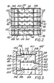
- the apparatus 8 additionally includes a plurality of liquid-vapour contact members 20, as shown in Figures 2 and 3. Between each pair of adjacent plates l4 there is a vertical array of such members 20.
- the members 20 each include a horizontal tray member 26 having a horizontal liquid bearing surface and perforations 36 formed therethrough. The peforations 36 are equally spaced from one another and have vertical axes.
- the members 20 have edges 22 and 24 in fluid-tight engagement with the plates l4 that they respectively abut.
- the liquid-vapour contact members 20 also include vertical partition members 28 which provide a weir 30 for each tray member 26 and a wall of a downcomer 34 for conducting liquid from said tray member to the tray member 26 immediately therebelow.
- Each downcomer 34 has a horizontal, liquid-collecting member 35 which is typically formed integral with the tray member 26 onto which said liquid is to be conducted by that downcomer in operation of the distillation apparatus 2.
- each plate l4 except the two that constitute the walls l2 has a multiplicity of orifices 38 formed therethrough.
- the orifices 38 may be arranged in rows 39, the distance between adjacent rows 39 being the same as the distance between adjacent tray members in each said array of such tray members.
- the position of each row 39 is such that in operation only vapour fully disengaged from liquid can pass therethrough. As shown in Figure 3, therefore, the rows of 39 of orifices 38 are typically positioned just below the level of respective tray members 26.
- the liquid-vapour contact members 20 may comprise an integral pressing or may be fabricated from two or more pieces of metal.
- the apparatus 8 is formed of aluminium, although stainless steel and copper are acceptable alternatives. Where the members 20 are formed from more than one piece of metal, they may be prefabricated or alternatively joined together with other parts of the apparatus 8.
- an assembly of all the plates l4, spacer members l6, and liquid-vapour contact members 20 is made as shown in Figures l to 3. All of the abutting surfaces may then be vacuum brazed together to form a unitary apparatus.
- the reboiler 4 and the condenser 6 may be brazed to the apparatus 8 at the same time.
- the method of manufacture may resemble that employed to make matrix heat exchangers. It is to be appreciated that the perforations 36 and orfices 38 are made prior to the commencement of the vacuum brazing.
- Each pair of adjacent plates l4 defines therebetween a discrete and separate flow path for the liquid from that defined by the other pairs of adjacent plates l4.
- liquid from the condenser 6 flows onto each top tray member 26 at the top of a vertical array flows therealong and is conducted by a downcomer 34 to the next tray member 26 therebelow.
- the liquid flow path is illustrated by the arrows 42.
- vapour ascending the column from the reboiler 4 As it passes along each tray member 26, liquid comes into intimate mass exchange relationship with vapour ascending the column from the reboiler 4 and passing through the perforations 36 in the tray members 26.
- the liquid as it descends the apparatus 8 tends to become richer in the less volatile component or components of the mixture being distilled, and the vapour as it ascends the column becomes richer in the more volatile component or components of the mixture being distilled.
- the upward passage of the vapour is indicated by the arrows 40.
- vapour there will be some exchange of vapour across the plates l4 through the orifices 38. Such exchange of vapour helps to limit any disparity between the composition of vapour between one pair of adjacent pipes l4 and that of vapour at the same level between another pair of plates l4.
- the apparatus shown in Figure l to 3 of the accompanying drawings is particularly intended for the distillation of air on board ship in order to produce either a nitrogen or an oxygen product, or both.
- the plates l4 help to limit displacement of the liquid on the tray members 26 in a direction generally at right angles to the direction of flow.
- the apparatus is mounted such that one wall l2 faces the stern and the other wall l2 faces the bow.
Landscapes
- Chemical & Material Sciences (AREA)
- Chemical Kinetics & Catalysis (AREA)
- Vaporization, Distillation, Condensation, Sublimation, And Cold Traps (AREA)
- Separation By Low-Temperature Treatments (AREA)
Applications Claiming Priority (2)
| Application Number | Priority Date | Filing Date | Title |
|---|---|---|---|
| GB858531685A GB8531685D0 (en) | 1985-12-23 | 1985-12-23 | Liquid-vapour contact apparatus |
| GB8531685 | 1985-12-23 |
Publications (3)
| Publication Number | Publication Date |
|---|---|
| EP0227420A2 true EP0227420A2 (fr) | 1987-07-01 |
| EP0227420A3 EP0227420A3 (en) | 1988-01-27 |
| EP0227420B1 EP0227420B1 (fr) | 1991-09-11 |
Family
ID=10590219
Family Applications (1)
| Application Number | Title | Priority Date | Filing Date |
|---|---|---|---|
| EP86309827A Expired - Lifetime EP0227420B1 (fr) | 1985-12-23 | 1986-12-16 | Dispositif de contact de vapeur/liquide |
Country Status (7)
| Country | Link |
|---|---|
| US (1) | US4738807A (fr) |
| EP (1) | EP0227420B1 (fr) |
| JP (1) | JPS62155902A (fr) |
| AU (1) | AU6657086A (fr) |
| DE (1) | DE3681418D1 (fr) |
| GB (2) | GB8531685D0 (fr) |
| ZA (1) | ZA868848B (fr) |
Cited By (4)
| Publication number | Priority date | Publication date | Assignee | Title |
|---|---|---|---|---|
| EP0372737A1 (fr) * | 1988-12-02 | 1990-06-13 | Imperial Chemical Industries Plc | Plaque à tamis pour effectuer un contact gaz-liquide et structure comprenant ladite plaque à tamis |
| EP0373772A1 (fr) * | 1988-12-02 | 1990-06-20 | Imperial Chemical Industries Plc | Structure pour effectuer un contact entre un gaz et un liquide et des parties de cette structure |
| FR2740470A1 (fr) * | 1995-10-27 | 1997-04-30 | Interbrew Sa | Dispositif pour l'elimination des composants volatils non desires contenus dans un mout de biere |
| EP1832570A2 (fr) * | 2002-07-31 | 2007-09-12 | The Procter and Gamble Company | Nouveaux solvants à changement de phase |
Families Citing this family (6)
| Publication number | Priority date | Publication date | Assignee | Title |
|---|---|---|---|---|
| US5277847A (en) * | 1989-03-08 | 1994-01-11 | Glitsch, Inc. | Method and apparatus for catalyst-downcomer-tray operation |
| US5525271A (en) * | 1994-10-27 | 1996-06-11 | The Boc Group, Inc. | Liquid-vapor contact device |
| US7563838B2 (en) * | 2002-07-31 | 2009-07-21 | The Procter & Gamble Company | Phase change solvents for thermoplastic polymers |
| US20040024110A1 (en) * | 2002-07-31 | 2004-02-05 | The Procter & Gamble Company | Phase change solvents for thermoplastic polymers |
| US7468411B2 (en) * | 2002-07-31 | 2008-12-23 | The Procter & Gamble Company | Thermoplastic elastomer compositions containing a phase change solvent and selected processing oils |
| DE102005013855A1 (de) * | 2005-03-24 | 2006-09-28 | Linde Ag | Stoffaustausch-Kolonne mit Austauschböden |
Citations (3)
| Publication number | Priority date | Publication date | Assignee | Title |
|---|---|---|---|---|
| GB1110608A (en) * | 1964-07-22 | 1968-04-24 | Applied Res And Engineering Lt | Improvements in and relating to evaporators |
| DE1904144A1 (de) * | 1969-01-28 | 1970-08-06 | Linde Ag | Vorrichtung zum Inkontaktbringen von Gas und Fluessigkeit |
| US3612494A (en) * | 1968-09-11 | 1971-10-12 | Kobe Steel Ltd | Gas-liquid contact apparatus |
Family Cites Families (10)
| Publication number | Priority date | Publication date | Assignee | Title |
|---|---|---|---|---|
| US291833A (en) * | 1884-01-08 | Still | ||
| US333464A (en) * | 1885-12-29 | Still | ||
| US243297A (en) * | 1881-06-21 | Alcohol-still | ||
| US2217386A (en) * | 1932-05-05 | 1940-10-08 | High Vacuum Processes Inc | Apparatus for distilling mineral oils |
| US2720389A (en) * | 1945-09-28 | 1955-10-11 | Air Prod Inc | Fractionating columns |
| DE1051805B (de) * | 1956-03-05 | 1959-03-05 | Bataafsche Petroleum | Kontaktkolonne mit in Abstaenden senkrecht untereinander angeordneten Boeden |
| US2895724A (en) * | 1956-03-21 | 1959-07-21 | Herrick L Johnston Inc | Gas-liquid contact apparatus |
| GB998822A (en) * | 1963-10-28 | 1965-07-21 | Marley Co | A fill assembly for a counterflow water cooling tower |
| GB1478459A (en) * | 1974-08-22 | 1977-06-29 | Cryoplants Ltd | Liquid-vapour contact column |
| US3983191A (en) * | 1975-11-10 | 1976-09-28 | The Trane Company | Brazed plate-type heat exchanger for nonadiabatic rectification |
-
1985
- 1985-12-23 GB GB858531685A patent/GB8531685D0/en active Pending
-
1986
- 1986-11-21 ZA ZA868848A patent/ZA868848B/xx unknown
- 1986-12-15 AU AU66570/86A patent/AU6657086A/en not_active Abandoned
- 1986-12-16 GB GB8630040A patent/GB2184366B/en not_active Expired - Fee Related
- 1986-12-16 DE DE8686309827T patent/DE3681418D1/de not_active Expired - Fee Related
- 1986-12-16 EP EP86309827A patent/EP0227420B1/fr not_active Expired - Lifetime
- 1986-12-22 JP JP61306171A patent/JPS62155902A/ja active Pending
- 1986-12-22 US US06/945,443 patent/US4738807A/en not_active Expired - Fee Related
Patent Citations (3)
| Publication number | Priority date | Publication date | Assignee | Title |
|---|---|---|---|---|
| GB1110608A (en) * | 1964-07-22 | 1968-04-24 | Applied Res And Engineering Lt | Improvements in and relating to evaporators |
| US3612494A (en) * | 1968-09-11 | 1971-10-12 | Kobe Steel Ltd | Gas-liquid contact apparatus |
| DE1904144A1 (de) * | 1969-01-28 | 1970-08-06 | Linde Ag | Vorrichtung zum Inkontaktbringen von Gas und Fluessigkeit |
Cited By (6)
| Publication number | Priority date | Publication date | Assignee | Title |
|---|---|---|---|---|
| EP0372737A1 (fr) * | 1988-12-02 | 1990-06-13 | Imperial Chemical Industries Plc | Plaque à tamis pour effectuer un contact gaz-liquide et structure comprenant ladite plaque à tamis |
| EP0373772A1 (fr) * | 1988-12-02 | 1990-06-20 | Imperial Chemical Industries Plc | Structure pour effectuer un contact entre un gaz et un liquide et des parties de cette structure |
| FR2740470A1 (fr) * | 1995-10-27 | 1997-04-30 | Interbrew Sa | Dispositif pour l'elimination des composants volatils non desires contenus dans un mout de biere |
| WO1997015654A1 (fr) * | 1995-10-27 | 1997-05-01 | Interbrew | Dispositif pour l'elimination des composants volatils non desires contenus dans un mout de biere |
| EP1832570A2 (fr) * | 2002-07-31 | 2007-09-12 | The Procter and Gamble Company | Nouveaux solvants à changement de phase |
| EP1832570A3 (fr) * | 2002-07-31 | 2008-03-05 | The Procter and Gamble Company | Nouveaux solvants à changement de phase |
Also Published As
| Publication number | Publication date |
|---|---|
| GB2184366B (en) | 1990-04-04 |
| GB8531685D0 (en) | 1986-02-05 |
| DE3681418D1 (de) | 1991-10-17 |
| AU6657086A (en) | 1987-06-25 |
| JPS62155902A (ja) | 1987-07-10 |
| EP0227420B1 (fr) | 1991-09-11 |
| GB8630040D0 (en) | 1987-01-28 |
| US4738807A (en) | 1988-04-19 |
| GB2184366A (en) | 1987-06-24 |
| EP0227420A3 (en) | 1988-01-27 |
| ZA868848B (en) | 1987-07-29 |
Similar Documents
| Publication | Publication Date | Title |
|---|---|---|
| EP0227420B1 (fr) | Dispositif de contact de vapeur/liquide | |
| US3434701A (en) | Vapor-liquid contacting apparatus | |
| US4657638A (en) | Distillation column | |
| EP0737498B1 (fr) | Plateau de contact gaz-liquide avec éléments de décharge triangulaires ayant des décharges sur les cÔtés | |
| CA1244631A (fr) | Colonne a transfert de masse | |
| EP0563900A1 (fr) | Séparation cryogénique d'air en utilisant un garnissage empilé au hasard | |
| EP0695921A1 (fr) | Echangeurs de chaleurs mince à constant descendant destiné à la rectification cryogénique | |
| US4304738A (en) | Packing Material and apparatus | |
| US5718127A (en) | Liquid vapor contact apparatus | |
| EP0361776B1 (fr) | Contact liquide-vapeur | |
| GB1532673A (en) | Plate-type heat exchanger | |
| US4556522A (en) | Sieve type distillation tray with curved baffles | |
| US4936954A (en) | Apparatus for separating liquid mixtures by pervaporation | |
| JPH09119783A (ja) | 液体−蒸気の接触装置 | |
| US2804292A (en) | Gas-liquid contact apparatus | |
| EP0319558A4 (fr) | Procede et dispositif de mise en contact vapeur-liquide. | |
| KR100383775B1 (ko) | 구조화된 패킹 | |
| KR102658183B1 (ko) | 물질 전달 칼럼에 사용하기 위한 구조화된 패킹 모듈 및 조립 방법 | |
| US6751986B2 (en) | Structured packing | |
| US20040099970A1 (en) | Tray column with deentrainment packing below the tray | |
| US3039751A (en) | Sectional contacting tray | |
| US4322234A (en) | Mist eliminator and wet deck pack | |
| GB2325175A (en) | Heat exchanger | |
| US3249516A (en) | Fractional distillation column with inclined wall sections | |
| US2460706A (en) | Rectification |
Legal Events
| Date | Code | Title | Description |
|---|---|---|---|
| PUAI | Public reference made under article 153(3) epc to a published international application that has entered the european phase |
Free format text: ORIGINAL CODE: 0009012 |
|
| AK | Designated contracting states |
Kind code of ref document: A2 Designated state(s): DE FR SE |
|
| PUAL | Search report despatched |
Free format text: ORIGINAL CODE: 0009013 |
|
| AK | Designated contracting states |
Kind code of ref document: A3 Designated state(s): DE FR SE |
|
| 17P | Request for examination filed |
Effective date: 19880722 |
|
| 17Q | First examination report despatched |
Effective date: 19900119 |
|
| GRAA | (expected) grant |
Free format text: ORIGINAL CODE: 0009210 |
|
| AK | Designated contracting states |
Kind code of ref document: B1 Designated state(s): DE FR SE |
|
| PG25 | Lapsed in a contracting state [announced via postgrant information from national office to epo] |
Ref country code: SE Effective date: 19910911 |
|
| ET | Fr: translation filed | ||
| REF | Corresponds to: |
Ref document number: 3681418 Country of ref document: DE Date of ref document: 19911017 |
|
| PGFP | Annual fee paid to national office [announced via postgrant information from national office to epo] |
Ref country code: SE Payment date: 19911113 Year of fee payment: 6 |
|
| PLBE | No opposition filed within time limit |
Free format text: ORIGINAL CODE: 0009261 |
|
| STAA | Information on the status of an ep patent application or granted ep patent |
Free format text: STATUS: NO OPPOSITION FILED WITHIN TIME LIMIT |
|
| 26N | No opposition filed | ||
| PGFP | Annual fee paid to national office [announced via postgrant information from national office to epo] |
Ref country code: FR Payment date: 19931109 Year of fee payment: 8 |
|
| PGFP | Annual fee paid to national office [announced via postgrant information from national office to epo] |
Ref country code: DE Payment date: 19931124 Year of fee payment: 8 |
|
| PG25 | Lapsed in a contracting state [announced via postgrant information from national office to epo] |
Ref country code: FR Effective date: 19950831 |
|
| PG25 | Lapsed in a contracting state [announced via postgrant information from national office to epo] |
Ref country code: DE Effective date: 19950901 |
|
| REG | Reference to a national code |
Ref country code: FR Ref legal event code: ST |