EP0227342A2 - Coving - Google Patents
Coving Download PDFInfo
- Publication number
- EP0227342A2 EP0227342A2 EP86309400A EP86309400A EP0227342A2 EP 0227342 A2 EP0227342 A2 EP 0227342A2 EP 86309400 A EP86309400 A EP 86309400A EP 86309400 A EP86309400 A EP 86309400A EP 0227342 A2 EP0227342 A2 EP 0227342A2
- Authority
- EP
- European Patent Office
- Prior art keywords
- coving
- ceiling
- strip
- wall
- abutment means
- Prior art date
- Legal status (The legal status is an assumption and is not a legal conclusion. Google has not performed a legal analysis and makes no representation as to the accuracy of the status listed.)
- Withdrawn
Links
Images
Classifications
-
- E—FIXED CONSTRUCTIONS
- E04—BUILDING
- E04F—FINISHING WORK ON BUILDINGS, e.g. STAIRS, FLOORS
- E04F19/00—Other details of constructional parts for finishing work on buildings
- E04F19/02—Borders; Finishing strips, e.g. beadings; Light coves
- E04F19/04—Borders; Finishing strips, e.g. beadings; Light coves for use between floor or ceiling and wall, e.g. skirtings
- E04F19/0436—Borders; Finishing strips, e.g. beadings; Light coves for use between floor or ceiling and wall, e.g. skirtings between ceiling and wall
Definitions
- the present invention relates to ceiling coving.
- the correct method of making a ceiling coving is by the use of plaster, using a purposely designed trowel for the application of the plaster. This method, apart from being time consuming, requires a skilled plasterer.
- coving may be formed of expanded polystyrene or paper covered plaster.
- Each of these covings has its attendant disadvantages. In particular, both materials are easily damaged, polystyrene because it dents easily and plaster because it is brittle and its ends are easily scuffed. Storage and transportation present problems as the covings can only be formed in long fixed lengths. Shorter lengths would result in too many joints.
- the joints between lengths are difficult to disguise when the coving is fixed to a ceiling and furthermore, in the case of polystyrene, the finished appearance leaves a lot to be desired aesthetically because even when painted the mottled texture of the material is in evidence through the paint.
- the joints also mean that the coving can only be given its finish coating after it has been fixed to the ceiling and if it should need to be painted a different colour from the remainder of the ceiling then painting it becomes both a skilled and a time consuming task.
- the present invention seeks to provide ceiling coving which mitigates at least some of the above disadvantages present in the prior art.
- ceiling coving comprising a generally flat, pliable, continuous coving strip, and abutment means for affixing to the wall and ceiling to constrain the coving strip to adopt a curved configuration.
- a method of securing coving to a ceiling which comprises cutting a desired length of pliable coving from a continuous strip, mounting abutment means on the ceiling and on the adjacent wall, the separation between the abutments on the wall and on the ceiling being less than the width of the coving strip, and pressing the coving strip into the corner between the wall and the ceiling, the abutment means serving to retain the coving strip in position and to constrain the coving strip in the shape of a curved surface.
- the coving is formed of a flat flexible plastics strip.
- the strip may itself be decorative, but alternatively the strip may be laminated, being formed of a base layer of polyvinyl chloride (PVC) and a decorative layer of paper.
- PVC polyvinyl chloride
- the coving strip may be formed with a pair of hinges extending parallel to its length, the hinges defining two lateral return portions which may be folded back during fixing to contact the surfaces of the wall and the ceiling concealed by the curved portion of the strip, disposed between the hinges.
- each hinge is formed of a pair of spaced hinge lines, the portion of the strip between the hinge lines protruding at right angles to the wall and ceiling when the coving strip is in position so as to space the curved portion of the coving from the wall and ceiling.
- the abutment means conveniently comprise brackets affixed between the wall and ceiling at regular intervals. If desired the ends of the brackets may be configured for interlocking engagement with the edges of the coving strip or the return portions of the coving strip.
- the coving strip may be formed by a variety of known method which need not be described in detail and amongst such methods one can mention extrusion moulding, hot rolling and cold rolling.
- the brackets may be made by injection moulding or as sheet metal stampings.
- a pattern may be embossed onto the visible surface of the coving strip and the strip may be supplied pre finished and ready for mounting.
- the advantage of the coving of the invention is that because it is pliable, it can be supplied in continuous rolls and the limitations imposed by the prior art on the length of any strip of coving are removed. Thus no length need have a joint and consequently there is no reason for not applying a finish coating before mounting the coving on a ceiling.
- the coving is furthermore held in position only by brackets and it is therefore possible to remove it. This may be desirable during the course of redecoration.
- the coving may be used to hide wires passed around a room, such as telephone wires. Furthermore, the coving material may itself be translucent permitting a light source to be concealed behind it and giving a pleasing effect when the lights are switched on.
- corner piece for a convex corner may also be used as an end stop.
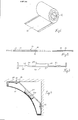
- Figure l depicts a roll l2 of coving strip l0 which is shown more clearly in the section of Figure 2.
- the strip l0 consists of a plastics base l4 covered with a decorative paper layer l6.
- the plastics material of the base may conveniently be polyvinyl chloride (PVC) and the adhesive used to secure the paper to the plastics material may be polyvinyl alcohol (PVA).
- PVC polyvinyl chloride
- PVA polyvinyl alcohol
- the plastics base l4 has along each edge two score lines l8 which permit the strip to be bent.
- brackets 20 are nailed to the corner as shown in Figure 4 with the nails 32 being inserted along a line marked at a given distance from the corner.
- the brackets 20 are fixed at regular intervals sufficient to hold the coving strip securely.
- Each bracket 20 is formed of plastics material and comprises an inner section 2l having a central boss 22 with a concave upper surface 24.
- Two film hinges 26 formed on each side of the inner section 2l connect the inner section to two angled end pieces 28 each formed with a hole 30 for receiving a nail 32.
- a pip 33 is also formed on the underside of each end piece 28, as viewed in Figure 3, to assist in holding the coving strip against the ceiling or wall.
- the brackets can be resiliently deflected away from the wall and ceiling sufficiently to permit the folded over edges of the coving strip l0 to be inserted. After slotting in of the edges of the strip l0, the latter is held in position by the pips 32. Double sided adhesive tape 40 is used to secure the coving strip l0 to the central boss 22 of each bracket 20 to maintain the strip in a bowed configuration.
- the parts of the coving strip disposed between the pairs of hinge lines lie at right angles to the wall or ceiling when the coving is mounted and therefore give an appearance which is the same as that of conventional coving.
- rolls of paper and plain PVC of the same width are rotatably supported in a jig.
- a run of material from the PVC roll passes through two rollers which score the surface t o form the hinge lines l8.
- the run then passes over a glue roller and a doctor blade which together apply a thin layer of PVA adhesive to the underside of the run.
- the two runs are then brought together in driven pressure rollers and after the adhesive has dried the completed strip is taken up on a roll driven by way of a slipping clutch from the motor driving the pressure rollers.
- the coving of the invention can, if necessary, be removed. This can considerably simplify redecoration of the room and provide a better finish, since the panels of wallpaper can finish behind the coving and, if a room is painted, the risk of painting the coving strip is avoided. Painting of the coving in a different colour is also considerably simplified.
- the coving strip may be painted before placing it on the ceiling, and can therefore be purchased ready for use. The task of installation is thus simplified.
- the strip may be embossed or electroless plated to provide an appearance not achievable with conventional methods.
- a further and important advantage of the coving of the invention is that the runs of coving have some flexibility, even when curved, and the coving can have a neat appearance even if the walls are slightly convex or concave in places, as is extremely common in practice.
- the strip may be formed entirely of plastics material and may be formed as an extrusion moulding.
- the surface of the strip may also be textured or embossed to give more freedom in the design of the coving.
Abstract
Description
- The present invention relates to ceiling coving.
- The correct method of making a ceiling coving is by the use of plaster, using a purposely designed trowel for the application of the plaster. This method, apart from being time consuming, requires a skilled plasterer.
- It is known to secure preformed coving to a ceiling. Such coving may be formed of expanded polystyrene or paper covered plaster. Each of these covings has its attendant disadvantages. In particular, both materials are easily damaged, polystyrene because it dents easily and plaster because it is brittle and its ends are easily scuffed. Storage and transportation present problems as the covings can only be formed in long fixed lengths. Shorter lengths would result in too many joints.
- The joints between lengths are difficult to disguise when the coving is fixed to a ceiling and furthermore, in the case of polystyrene, the finished appearance leaves a lot to be desired aesthetically because even when painted the mottled texture of the material is in evidence through the paint. Of course, the joints also mean that the coving can only be given its finish coating after it has been fixed to the ceiling and if it should need to be painted a different colour from the remainder of the ceiling then painting it becomes both a skilled and a time consuming task.
- The present invention seeks to provide ceiling coving which mitigates at least some of the above disadvantages present in the prior art.
- According to the present invention, there is provided ceiling coving comprising a generally flat, pliable, continuous coving strip, and abutment means for affixing to the wall and ceiling to constrain the coving strip to adopt a curved configuration.
- In a second aspect of the invention, there is provided a method of securing coving to a ceiling, which comprises cutting a desired length of pliable coving from a continuous strip, mounting abutment means on the ceiling and on the adjacent wall, the separation between the abutments on the wall and on the ceiling being less than the width of the coving strip, and pressing the coving strip into the corner between the wall and the ceiling, the abutment means serving to retain the coving strip in position and to constrain the coving strip in the shape of a curved surface.
- In a particularly simple embodiment, the coving is formed of a flat flexible plastics strip. The strip may itself be decorative, but alternatively the strip may be laminated, being formed of a base layer of polyvinyl chloride (PVC) and a decorative layer of paper.
- The coving strip may be formed with a pair of hinges extending parallel to its length, the hinges defining two lateral return portions which may be folded back during fixing to contact the surfaces of the wall and the ceiling concealed by the curved portion of the strip, disposed between the hinges.
- Advantageously, each hinge is formed of a pair of spaced hinge lines, the portion of the strip between the hinge lines protruding at right angles to the wall and ceiling when the coving strip is in position so as to space the curved portion of the coving from the wall and ceiling.
- The abutment means conveniently comprise brackets affixed between the wall and ceiling at regular intervals. If desired the ends of the brackets may be configured for interlocking engagement with the edges of the coving strip or the return portions of the coving strip.
- The coving strip may be formed by a variety of known method which need not be described in detail and amongst such methods one can mention extrusion moulding, hot rolling and cold rolling. The brackets may be made by injection moulding or as sheet metal stampings.
- If desired a pattern may be embossed onto the visible surface of the coving strip and the strip may be supplied pre finished and ready for mounting.
- The advantage of the coving of the invention is that because it is pliable, it can be supplied in continuous rolls and the limitations imposed by the prior art on the length of any strip of coving are removed. Thus no length need have a joint and consequently there is no reason for not applying a finish coating before mounting the coving on a ceiling.
- The coving is furthermore held in position only by brackets and it is therefore possible to remove it. This may be desirable during the course of redecoration.
- The coving may be used to hide wires passed around a room, such as telephone wires. Furthermore, the coving material may itself be translucent permitting a light source to be concealed behind it and giving a pleasing effect when the lights are switched on.
- For the corners and ends of the coving moulded corner pieces may be provided and these may be formed for both convex and concave corners. The corner piece for a convex corner may also be used as an end stop.
- The invention will now be described further, by way of example, with reference to the accompanying drawings, in which :
- Figure l shows a roll of coving strip,
- Figure 2 is a section through the coving strip in Figure l,
- Figure 3 is a section through a bracket for securing the coving strip to a ceiling, and
- Figure 4 is a section showing the strip mounted in a corner between a wall and a ceiling and held by means of the bracket of Figure 3.
- Figure l depicts a roll l2 of coving strip l0 which is shown more clearly in the section of Figure 2. The strip l0 consists of a plastics base l4 covered with a decorative paper layer l6. The plastics material of the base may conveniently be polyvinyl chloride (PVC) and the adhesive used to secure the paper to the plastics material may be polyvinyl alcohol (PVA). The plastics base l4 has along each edge two score lines l8 which permit the strip to be bent.
- To mount a coving strip,
brackets 20 are nailed to the corner as shown in Figure 4 with thenails 32 being inserted along a line marked at a given distance from the corner. Thebrackets 20 are fixed at regular intervals sufficient to hold the coving strip securely. - Each
bracket 20 is formed of plastics material and comprises an inner section 2l having acentral boss 22 with a concaveupper surface 24. Twofilm hinges 26 formed on each side of the inner section 2l connect the inner section to twoangled end pieces 28 each formed with ahole 30 for receiving anail 32. Apip 33 is also formed on the underside of eachend piece 28, as viewed in Figure 3, to assist in holding the coving strip against the ceiling or wall. - Because the
nails 32 pass through the end pieces at a distance from the ends of the brackets, the latter can be resiliently deflected away from the wall and ceiling sufficiently to permit the folded over edges of the coving strip l0 to be inserted. After slotting in of the edges of the strip l0, the latter is held in position by thepips 32. Double sidedadhesive tape 40 is used to secure the coving strip l0 to thecentral boss 22 of eachbracket 20 to maintain the strip in a bowed configuration. - The parts of the coving strip disposed between the pairs of hinge lines lie at right angles to the wall or ceiling when the coving is mounted and therefore give an appearance which is the same as that of conventional coving.
- At corners and at exposed ends of the coving, moulded corner pieces, not shown are secured to the ceiling and these may be suitably designed for convex and concave corners. The holes for the nails used to secure the corner pieces may be covered by blanking plugs.
- To form the coving strip l0, rolls of paper and plain PVC of the same width are rotatably supported in a jig. A run of material from the PVC roll passes through two rollers which score the surface t o form the hinge lines l8. The run then passes over a glue roller and a doctor blade which together apply a thin layer of PVA adhesive to the underside of the run. The two runs are then brought together in driven pressure rollers and after the adhesive has dried the completed strip is taken up on a roll driven by way of a slipping clutch from the motor driving the pressure rollers.
- In addition to assuring a pleasing appearance, unmarred by any visible means of fixing the coving to the ceiling, the coving of the invention can, if necessary, be removed. This can considerably simplify redecoration of the room and provide a better finish, since the panels of wallpaper can finish behind the coving and, if a room is painted, the risk of painting the coving strip is avoided. Painting of the coving in a different colour is also considerably simplified.
- The coving strip may be painted before placing it on the ceiling, and can therefore be purchased ready for use. The task of installation is thus simplified. The strip may be embossed or electroless plated to provide an appearance not achievable with conventional methods.
- A further and important advantage of the coving of the invention is that the runs of coving have some flexibility, even when curved, and the coving can have a neat appearance even if the walls are slightly convex or concave in places, as is extremely common in practice.
- It should be mentioned that the invention has been described only by way of example and various alternative embodiments are possible within the scope of the invention as set forth in the appended claims. In particular, the strip may be formed entirely of plastics material and may be formed as an extrusion moulding. The surface of the strip may also be textured or embossed to give more freedom in the design of the coving.
Claims (8)
Applications Claiming Priority (2)
| Application Number | Priority Date | Filing Date | Title |
|---|---|---|---|
| GB858529541A GB8529541D0 (en) | 1985-12-05 | 1985-12-05 | Coving |
| GB8529541 | 1985-12-05 |
Publications (2)
| Publication Number | Publication Date |
|---|---|
| EP0227342A2 true EP0227342A2 (en) | 1987-07-01 |
| EP0227342A3 EP0227342A3 (en) | 1988-05-11 |
Family
ID=10589059
Family Applications (1)
| Application Number | Title | Priority Date | Filing Date |
|---|---|---|---|
| EP86309400A Withdrawn EP0227342A3 (en) | 1985-12-05 | 1986-12-03 | Coving |
Country Status (2)
| Country | Link |
|---|---|
| EP (1) | EP0227342A3 (en) |
| GB (1) | GB8529541D0 (en) |
Cited By (10)
| Publication number | Priority date | Publication date | Assignee | Title |
|---|---|---|---|---|
| EP0441759A1 (en) * | 1990-02-08 | 1991-08-14 | Rockwool Aktiebolaget | Vaulted acoustic element |
| GB2283044A (en) * | 1993-10-22 | 1995-04-26 | Aelwyn Rees | Support member for e.g. a ceiling covering |
| FR2716478A1 (en) * | 1994-02-23 | 1995-08-25 | Hopenko Marie Francoise | Suspended ceiling finishing rail |
| AT404617B (en) * | 1997-01-09 | 1999-01-25 | Neuhofer Franz Jun | DEVICE FOR ATTACHING LENGTH-SLOTTED COVER STRIPS |
| EP1442184A1 (en) * | 2001-06-06 | 2004-08-04 | Leslie William Pickup | Ornament and bracket |
| US7451574B2 (en) * | 2005-03-07 | 2008-11-18 | Spexco, Llc | Crown molding |
| US7958685B2 (en) * | 2007-05-03 | 2011-06-14 | Todd Rowohlt | Crown extrusion |
| KR101185077B1 (en) * | 2011-04-21 | 2012-09-27 | 양재원 | Corner covering apparatus |
| US8534016B2 (en) * | 2009-03-30 | 2013-09-17 | Robert Depaul | Corner wall conduit |
| DE102017114222A1 (en) * | 2017-06-27 | 2018-12-27 | iTEKTUR UG (haftungsbeschränkt) | lighting device |
Citations (6)
| Publication number | Priority date | Publication date | Assignee | Title |
|---|---|---|---|---|
| US1919300A (en) * | 1931-08-25 | 1933-07-25 | American Telephone & Telegraph | Molding |
| CH407510A (en) * | 1963-10-17 | 1966-02-15 | Notz Otto | Cover strip and process for their manufacture |
| US3331172A (en) * | 1965-03-25 | 1967-07-18 | Sonoco Products Co | Molding assembly |
| GB1238526A (en) * | 1968-07-09 | 1971-07-07 | ||
| GB1572517A (en) * | 1978-02-21 | 1980-07-30 | Ravenscroft E | Cornices |
| GB2118825A (en) * | 1982-04-28 | 1983-11-09 | David Adams | Support arrangement for decorative strip |
-
1985
- 1985-12-05 GB GB858529541A patent/GB8529541D0/en active Pending
-
1986
- 1986-12-03 EP EP86309400A patent/EP0227342A3/en not_active Withdrawn
Patent Citations (6)
| Publication number | Priority date | Publication date | Assignee | Title |
|---|---|---|---|---|
| US1919300A (en) * | 1931-08-25 | 1933-07-25 | American Telephone & Telegraph | Molding |
| CH407510A (en) * | 1963-10-17 | 1966-02-15 | Notz Otto | Cover strip and process for their manufacture |
| US3331172A (en) * | 1965-03-25 | 1967-07-18 | Sonoco Products Co | Molding assembly |
| GB1238526A (en) * | 1968-07-09 | 1971-07-07 | ||
| GB1572517A (en) * | 1978-02-21 | 1980-07-30 | Ravenscroft E | Cornices |
| GB2118825A (en) * | 1982-04-28 | 1983-11-09 | David Adams | Support arrangement for decorative strip |
Cited By (12)
| Publication number | Priority date | Publication date | Assignee | Title |
|---|---|---|---|---|
| EP0441759A1 (en) * | 1990-02-08 | 1991-08-14 | Rockwool Aktiebolaget | Vaulted acoustic element |
| GB2283044A (en) * | 1993-10-22 | 1995-04-26 | Aelwyn Rees | Support member for e.g. a ceiling covering |
| FR2716478A1 (en) * | 1994-02-23 | 1995-08-25 | Hopenko Marie Francoise | Suspended ceiling finishing rail |
| AT404617B (en) * | 1997-01-09 | 1999-01-25 | Neuhofer Franz Jun | DEVICE FOR ATTACHING LENGTH-SLOTTED COVER STRIPS |
| US5890267A (en) * | 1997-01-09 | 1999-04-06 | Neuhofer, Jr.; Franz | Attachment fitting for longitudinally grooved covering strips |
| EP1442184A1 (en) * | 2001-06-06 | 2004-08-04 | Leslie William Pickup | Ornament and bracket |
| EP1442184A4 (en) * | 2001-06-06 | 2007-07-04 | Leslie William Pickup | Ornament and bracket |
| US7451574B2 (en) * | 2005-03-07 | 2008-11-18 | Spexco, Llc | Crown molding |
| US7958685B2 (en) * | 2007-05-03 | 2011-06-14 | Todd Rowohlt | Crown extrusion |
| US8534016B2 (en) * | 2009-03-30 | 2013-09-17 | Robert Depaul | Corner wall conduit |
| KR101185077B1 (en) * | 2011-04-21 | 2012-09-27 | 양재원 | Corner covering apparatus |
| DE102017114222A1 (en) * | 2017-06-27 | 2018-12-27 | iTEKTUR UG (haftungsbeschränkt) | lighting device |
Also Published As
| Publication number | Publication date |
|---|---|
| EP0227342A3 (en) | 1988-05-11 |
| GB8529541D0 (en) | 1986-01-08 |
Similar Documents
| Publication | Publication Date | Title |
|---|---|---|
| US4313991A (en) | Seam-covering device | |
| CA2072005C (en) | Predecorated wallboard joint and method of joining predecorated wallboards to form a concealed joint | |
| EP0580009B1 (en) | Decorative molding strip | |
| US5531050A (en) | Drywall corner finishing device | |
| US4553363A (en) | Outside wallboard corner construction and edging member for said corners | |
| US7793475B2 (en) | Molding member having a plurality of flanges for engaging with drywall finishing material | |
| US4053008A (en) | Support molding for fabric wall coverings | |
| US4151762A (en) | Tool for inserting fabric in molding | |
| US5459969A (en) | Drywall corner finishing device | |
| JP2004517234A5 (en) | ||
| EP0227342A2 (en) | Coving | |
| US5079880A (en) | Trim for covering and securing dry wall adjacent to surrounding portion of a bathtub or shower stall | |
| US5799458A (en) | Back-blocking device and method for drywall joint attachment | |
| US7383668B1 (en) | Vinyl bead with flex wings | |
| US5916101A (en) | Drywall corner finishing device | |
| US20030014931A1 (en) | Plaster crown molding system for indirect lighting | |
| EP1442184B1 (en) | Methode for removably mounting a cornice and cornice assembly | |
| US20030005660A1 (en) | Drywall corner finishing device | |
| US20050166527A1 (en) | Finish trim components | |
| CA2277827C (en) | Drywall corner finishing device | |
| US20030168760A1 (en) | Method of making and assembling foam crown molding | |
| EP1157177B1 (en) | A finishing device for forming a joint or a corner between two drywall panels | |
| AU720739B2 (en) | Cornices and mouldings | |
| JPH036744Y2 (en) | ||
| AU2001263650B2 (en) | Connector for cornices |
Legal Events
| Date | Code | Title | Description |
|---|---|---|---|
| PUAI | Public reference made under article 153(3) epc to a published international application that has entered the european phase |
Free format text: ORIGINAL CODE: 0009012 |
|
| AK | Designated contracting states |
Kind code of ref document: A2 Designated state(s): BE DE FR GB IT NL SE |
|
| PUAL | Search report despatched |
Free format text: ORIGINAL CODE: 0009013 |
|
| AK | Designated contracting states |
Kind code of ref document: A3 Designated state(s): BE DE FR GB IT NL SE |
|
| STAA | Information on the status of an ep patent application or granted ep patent |
Free format text: STATUS: THE APPLICATION IS DEEMED TO BE WITHDRAWN |
|
| 18D | Application deemed to be withdrawn |
Effective date: 19890112 |
|
| RIN1 | Information on inventor provided before grant (corrected) |
Inventor name: GLANVILL, KEITH BIRKETT Inventor name: REID, JOHN NICHOLAS |