EP0227207B1 - Concrete reinforcing unit - Google Patents
Concrete reinforcing unit Download PDFInfo
- Publication number
- EP0227207B1 EP0227207B1 EP19860306037 EP86306037A EP0227207B1 EP 0227207 B1 EP0227207 B1 EP 0227207B1 EP 19860306037 EP19860306037 EP 19860306037 EP 86306037 A EP86306037 A EP 86306037A EP 0227207 B1 EP0227207 B1 EP 0227207B1
- Authority
- EP
- European Patent Office
- Prior art keywords
- resin
- reinforcing elements
- concrete
- reinforcing
- fiber
- Prior art date
- Legal status (The legal status is an assumption and is not a legal conclusion. Google has not performed a legal analysis and makes no representation as to the accuracy of the status listed.)
- Expired - Lifetime
Links
Images


Classifications
-
- E—FIXED CONSTRUCTIONS
- E04—BUILDING
- E04C—STRUCTURAL ELEMENTS; BUILDING MATERIALS
- E04C5/00—Reinforcing elements, e.g. for concrete; Auxiliary elements therefor
- E04C5/16—Auxiliary parts for reinforcements, e.g. connectors, spacers, stirrups
-
- E—FIXED CONSTRUCTIONS
- E04—BUILDING
- E04C—STRUCTURAL ELEMENTS; BUILDING MATERIALS
- E04C5/00—Reinforcing elements, e.g. for concrete; Auxiliary elements therefor
- E04C5/07—Reinforcing elements of material other than metal, e.g. of glass, of plastics, or not exclusively made of metal
-
- Y—GENERAL TAGGING OF NEW TECHNOLOGICAL DEVELOPMENTS; GENERAL TAGGING OF CROSS-SECTIONAL TECHNOLOGIES SPANNING OVER SEVERAL SECTIONS OF THE IPC; TECHNICAL SUBJECTS COVERED BY FORMER USPC CROSS-REFERENCE ART COLLECTIONS [XRACs] AND DIGESTS
- Y10—TECHNICAL SUBJECTS COVERED BY FORMER USPC
- Y10T—TECHNICAL SUBJECTS COVERED BY FORMER US CLASSIFICATION
- Y10T428/00—Stock material or miscellaneous articles
- Y10T428/24—Structurally defined web or sheet [e.g., overall dimension, etc.]
- Y10T428/24058—Structurally defined web or sheet [e.g., overall dimension, etc.] including grain, strips, or filamentary elements in respective layers or components in angular relation
- Y10T428/24074—Strand or strand-portions
- Y10T428/24091—Strand or strand-portions with additional layer[s]
- Y10T428/24099—On each side of strands or strand-portions
-
- Y—GENERAL TAGGING OF NEW TECHNOLOGICAL DEVELOPMENTS; GENERAL TAGGING OF CROSS-SECTIONAL TECHNOLOGIES SPANNING OVER SEVERAL SECTIONS OF THE IPC; TECHNICAL SUBJECTS COVERED BY FORMER USPC CROSS-REFERENCE ART COLLECTIONS [XRACs] AND DIGESTS
- Y10—TECHNICAL SUBJECTS COVERED BY FORMER USPC
- Y10T—TECHNICAL SUBJECTS COVERED BY FORMER US CLASSIFICATION
- Y10T428/00—Stock material or miscellaneous articles
- Y10T428/249921—Web or sheet containing structurally defined element or component
- Y10T428/249924—Noninterengaged fiber-containing paper-free web or sheet which is not of specified porosity
- Y10T428/24994—Fiber embedded in or on the surface of a polymeric matrix
- Y10T428/249942—Fibers are aligned substantially parallel
- Y10T428/249946—Glass fiber
-
- Y—GENERAL TAGGING OF NEW TECHNOLOGICAL DEVELOPMENTS; GENERAL TAGGING OF CROSS-SECTIONAL TECHNOLOGIES SPANNING OVER SEVERAL SECTIONS OF THE IPC; TECHNICAL SUBJECTS COVERED BY FORMER USPC CROSS-REFERENCE ART COLLECTIONS [XRACs] AND DIGESTS
- Y10—TECHNICAL SUBJECTS COVERED BY FORMER USPC
- Y10T—TECHNICAL SUBJECTS COVERED BY FORMER US CLASSIFICATION
- Y10T442/00—Fabric [woven, knitted, or nonwoven textile or cloth, etc.]
- Y10T442/10—Scrim [e.g., open net or mesh, gauze, loose or open weave or knit, etc.]
- Y10T442/102—Woven scrim
- Y10T442/133—Inorganic fiber-containing scrim
- Y10T442/14—Including an additional scrim layer
Definitions
- the present invention relates to a concrete reinforcing unit which is suitably used as a replacement of the reinforcing steel in various concrete constructions.
- girders and columns of a building have concrete reinforcements embedded in concrete, including steel frameworks having main reinforcements wound with additional reinforcements for shearing such as hoops, stirrups and spiral hoops.
- DE-A-3 032 533 discloses a mesh made of a synthetic resin and glass fibers impregnated therein, which may be used for reinforcing plastic items, concrete items, and the like.
- GB-A-2 070 098 discloses a panel structure in the form of a grid made from a mouldable synthetic resin reinforced by fibers laid in rows crossing each other.
- the present invention provides a reinforcing unit for use in a concrete structure comprising two or more systems of elongate reinforcing elements, the elements in each system being parallel to one another, which cross at a number of crossing portions, so as to form at least one planar grid member, each of the reinforcing elements comprising longitudinally extending textile filamentary material embedded in a resin matrix, characterised in that the filamentary material is in the form of stacked parallel rows each of which contain a plurality of parallel filaments aligned side by side, the rows in one system of reinforcing elements interleaving with the rows of the other system(s) of reinforcing elements at their crossing portions, the crossing portions of the reinforcing elements being press-formed so as to be of substantially equal thickness with the non-crossing portions.
- first and second reinforcing elements and first and second textiles will be referred to as first and second reinforcing elements and first and second textiles as appropriate.
- the first reinforcing elements and the second reinforcing elements may have a substantially rectangular cross-section.
- the grid member may be substantially two-dimensional and be embedded in the concrete so that it is parallel with a surface of the concrete.
- the grid member may be used in the number of at least two, and adjacent grid members may be disposed to overlap each other at peripheral portions thereof.
- the first textiles are each formed into at least one structure of a tow, roving, strand, yarn, thread, sennit and braid, and are made of at least one fiber selected from the group consisting of a glass fiber, carbon fiber, aramid fiber, boron fiber, ceramic fiber, and metallic fiber.
- the first resin matrixes are preferably made of a substance selected from the group consisting of an epoxy resin, unsaturated polyester resin, vinyl ester resin, polyurethane resin, diallylphthalate resin, phenolic plastic, polyacetal, saturated polyester resin, polyamide resin, ploystyrene resin, polycarbonate resin, polyvinyl chloride resin, polyethylene resin, polypropylene resin and acrylic resin.
- the first reinforcing elements and the second reinforcing elements each contain about 10 to about 90 % by volume of the first textiles and about 90 to about 10 % by volume of the first resin.
- first reinforcing elements and the second reinforcing elements each contain about 30 to about 70 % by volume of a glass fiber and about 70 to about 30 % by volume of a vinyl ester resin.
- the first reinforcing elements and the second reinforcing elements each contain about 20 to 60 % by volume of a carbon fiber and about 80 to about 40 % by volume of a vinyl ester resin.
- the concrete reinforcing unit may further comprise: at least three longitudinal parallel reinforcing elements disposed in a three-dimensional manner; and second attaching means for attaching said longitudinal parallel reinforcing elements to the first reinforcing elements and the second reinforcing elements, and wherein the first reinforcing elements and second reinforcing elements cross corresponding longitudinal reinforcing elements at second crossing portions and are attached to the corresponding longitudinal reinforcements at second crossing portions with the second attaching means.
- Such a construction provides a three-dimentional concrete reinforcing unit having an excellent workability, transportability and a relatively large size as compared to the prior art concrete reinforcement. Further, such a concrete reinforcing unit is excellent for corrosion resistance and is hence useful in concrete construction.
- the longitudinal reinforcing elements may each comprise: at least one row of second parallel textiles; and a second resin matrix, nade of a second resin, for integrally bonding said row of the second textiles.
- the textile rows of each of a corresponding first reinforcing element, a corresponding second reinforcing element and a corresponding longitudinal reinforcing element may be alternatively stacked at each of said second crossing portions.
- the second attaching means may be one of the first resin and the second resin.
- first reinforcing elements and the second reinforcing elements preferably extend between two adjacent longitudinal reinforcing elements so that the first reinforcing elements and the second reinforcing elements each generally define a spiral in the overall shape thereof.
- the second textiles may be each formed into at least one structure of a tow, roving, strand, yarn, thread, sennit and braid, and wherein the second textiles are each made of at least one fiber selected from the group consisting of a glass fiber, carbon fiber, aramid fiber, boron fiber, ceramic fiber, and metallic fiber.
- the second resin matrixes may each be made of a substance selected from the group consisting of an epoxy resin, unsaturated polyester resin, vinyl ester resin, polyurethane resin, diallylphthalate resin, phenolic plastic, polyacetal, saturated polyester resin, polyamide resin, ploystyrene resin, polycarbonate resin, polyvinyl chloride resin, polyethylene resin, polypropylene resin and acrylic resin.
- the longitudinal reinforcing elements may each contain about 10 to about 90 % by volume of the second textiles and about 90 to about 10 % by volume of the second resin.
- the longitudinal reinforcing elements each contain about 30 to about 70 % by volume of a glass fiber and about 70 to about 30 % by volume of a vinyl ester resin.
- the longitudinal reinforcing elements each contain about 20 to 60 % by volume of a carbon fiber and about 80 to about 40 % by volume of a vinyl ester resin.
- FIGS. 1 to 3 illustrate a concrete reinforcing unit 30 in the shape of a grid according to the present invention.
- the reinforcing unit 30 is suitably used as a reinforcement which is embedded in concrete to form a wall or a floor of a building.
- the reinforcing unit 30 includes a plurality of first parallel reinforcing elements 32 and a plurality of second parallel reinforcing elements 34 crossing the first parallel reinforcing elements to form a grid, all the first and second reinforcing elements 32 and 34 being disposed in a plane.
- the number of the first reinforcing elements 32 is five and the number of the second reinforcing elements 34 is four. As illustrated in FIG.
- each of the first and second reinforcing elements 32 and 34 includes eight vertically stacked rows of textiles 36 which are bonded together through a resin matrix 38.
- Each textile row 40 has four parallel textiles 36, rovings in this embodiment, contacting or nearly contacting adjacent textile or textiles 36 of the same row 40.
- Crossing portions 42 of both the first and second reinforcing elements 32 and 34 is illustrated in a sectional view in FIG. 3, in which eight textile rows 40 of the first reinforcing elements 32 and eight textile rows 40 of the second reinforcing elements 34 are alternatively stacked, so that the crossing portion 42 has 16 rows of textiles in total in this embodiment.
- the number of textile rows 40 in each crossing portion 42 may be two or more.
- Each crossing portion 42 and non-crossing portions of the first and second reinforcing elements 32 and 34 are substantially equal in thickness T, and hence, the upper and lower faces of the reinforcing unit 30 are each at an equal level.
- the upper and lower faces of the reinforcing unit 30 may be roughened for enhancing adhesive strength to the resin of the resin matrix 38.
- glass fiber and carbon fiber are used due to relatively light weight and high strength.
- the resin matrix 38 which bonds textile rows 40 together is, according to the present invention, preferably made of a vinyl ester resin due to its excellent adhesiveness to textiles 36 and sufficient strength but the resin forming the resin matrix 38 depends on the kind of textiles used.
- Use may be made of other synthetic resins such as an epoxy resin, unsaturated polyester resin, polyurethane resin, diallylphthalate resin, phenolic plastic, polyacetal, saturated polyester resin, polyamide resin, ploystyrene resin, polycarbonate resin, polyvinyl chloride resin, polyethylene resin, polypropylene resin and acrylic resin.
- the reinforcing unit 30, generally contains about 10 to about 90 % by volume of the textile 36 but the ratio is selected in view of the kind and strength of the textiles 36 and use of the reinforcing unit.
- the reinforcing unit 30 for building constructions includes preferably about 30 to about 70 % by volume of the glass fiber. Below about 30 %, strength of the resultant reinforcing unit reduces and beyond about 70 %, the resulting reinforcing unit is costly in the glass fiber.
- the reinforcing unit includes preferably about 20 to about 60 % by volume of the pitch carbon fiber. Below about 20 % by volume of the pitch carbon fiber, the resulting reinforcing unit is rather inferior in strength, and above about 60 %, cost performance of the carbon fiber is considerably reduced although the reinforcing unit has relatively high strength.
- the reinforcing unit 30, according to the present invention may be produced by means of an apparatus as illustrated in FIGS. 4 and 5, although in this apparatus a grid reinforcing unit having five first reinforcing elements 32 and nine second reinforcing elements 34 is to be fabricated.
- the reference numeral 50 designates a rectangular base plate having chamfered upper edges 52. Taper pins 54 are mounted in the number of 28 at their smaller diameter ends to lateral faces 56 of the base plate 50 so that they are located to correspond to pitches of the first and second reinforcing elements 32 and 34.
- a row 60 of continuous textiles 62 which are impregnated with a resin for forming the resin matrix 38, are hooked around each pin 54 to extend it tightly between facing pins 54, for example, in a longitudinal direction L and then in a transverse direction T in the order I-XXVIII as shown in FIG. 4.
- the row of the continuous textiles 62 is returned from the pin XXVIII to the pin I and then the operation described above is repeated.
- Adjacent textile rows 60 and 60 at crossing portions 42 cross each other. That is, textile rows example 1 of the first and second reinforcing elements 32 an 34 are alternatively stacked at the crossing portions 42.
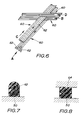
- FIG. 6 illustrates one crossing portion 42 of four rows 60 of textiles 62 impregnated with a resin, each textile row 60 including four textiles 62, rovings in this embodiment.
- the four textile rows 60 are stacked in the alphabetical order A-D as illustrated.
- the above-stated operation which consists of four steps A to D is repeated four times since each crossing portion 42 thereof includes 16 rows vertically stacked.
- sufficient tension must be applied to the textiles 62 to keep them tight.
- This process is manually carried out, but may be achieved automatically by means of a numerically controlled machine which is actuated on a predetermined program describing a two-dimensional pattern of the grid member 30. Then, the grid member thus formed (FIG.
- each of the first and the second reinforcing elements 32 and 34 is cut at their opposite ends near the pins 54 and then removed from the base plate 50.
- the grid member 30 is completed.
- the base plate and the depressing plate should have poor adhesive properties to the resin.
- the working faces of the base plate 50 and the depressing plate 64 are coated with Teflon resin and the pins 54 are applied with a wax for this purpose.
- Rough surfaces may be formed in the upper or lower faces of the reinforcing unit by providing irregularity to the lower face of the depressing unit or the upper face of the base plate. The rough faces of the reinforcing unit enhance its adhesive property to the concrete in which it is embedded.
- first reinforcing elements 32 and 32 and two adjacent second reinforcing elements 34 and 34 may form a diaper pattern.
- the grid member 30 may have bias reinforcing elements crossing both the first and second reinforcing elements 32 and 34. In this case, a reinforcing unit having a hexagonal pattern may be formed.
- the grid member 30 has a constant pitch, but a portion of the grid member 30 may have a pitch larger than the other portion, in which case a rectangular pattern may be defined.
- first and second reinforcing elements For producing a grid reinforcing unit, a plurality of separate first and second reinforcing elements previously set may be attached.
- the separate first and second reinforcing elements are bound with strings or fastened with bolts and nuts at the crossing portions. Alternatively, they may be bonded or attached by melting.
- FIGS. 9 and 10 illustrate another concrete reinforcement unit 70 having a lattice girder structure according to the present invention.
- the reinforcement unit 70 is used as a reinforcement for a column or a beam of a concrete building.
- the reinforcement unit 70 includes four parallel longitudinal reinforcing elements 72, four first spiral reinforcing elements 74 as lattice bars and four second spiral reinforcing elements 76 as the other lattice bars.
- the longitudinal reinforcing elements 72 are disposed in a three-dimensional manner with an equal spacing.
- each of the longitudinal reinforcing elements 72 and the spiral reinforcing elements 74, 76 has a structure similar to the structure, as shown in FIG. 2, of the reinforcing elements 32 and 34 of the grid member 30, but it includes four textile rows 80 and each row consists of five textiles 36.
- the textiles of these elements 72, 74 and 76 may be the same in their material and structure as the textiles of the grid member 30 and are contained in a resin matrix 82 which may also be made of the same material as the resin matrix 38 of the preceding embodiment.
- the textiles 36 of each of the longitudinal reinforcing elements 72 and the first and second spiral reinforcing elements 74 and 76 are integrally bonded by the resin matrix 82 of the same resin.
- the longitudinal reinforcing elements and the first and second spiral reinforcing elements are substantially equal in the ratio of the textiles over the resin to those of the first embodiments.
- textile rows 80 of a corresponding longitudinal reinforcing element 72 and corresponding first and second spiral reinforcing elements 74 and 76 are, as illustrated in FIG. 12, alternatively stacked to form at least three stacked rows, twelve rows in this embodiment.
- Each of the crossing portions B have textile rows 80 of the first and the second spiral reinforcing elements 74 and 76 alternatively stacked in the same manner as the crossing portions 42 of the reinforcing elements 32 and 34 of the grid member shown in FIG. 3 but in this embodiment the total number of the textile rows 80 stacked is eight with each row including five textiles 36.
- Thickness T of each of the longitudinal reinforcing elements 72 and the first and second spiral reinforcing elements 74 and 76 is substantially equal.
- the concrete reinforcing unit 70 is fabricated by means of an apparatus illustrated in FIGS. 14 and 15, in which the reference numeral 90 designates a rotation shaft. Opposite ends of the rotation shaft 90 are rotatably supported on a pair of bearing stands 92 through ball bearings not shown.
- the rotation shaft 90 has six sets of equidistant supporting arms 94. Each supporting arm set includes four supporting arms 94 projecting radially outwardly from the rotation shaft 90 at equal angular intervals, i.e., 90°.
- the supporting arms 94 are disposed so that they are axially aligned for forming four axial rows of supporting arms 94 as shown in FIG. 15. As best shown in FIG.
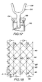
- each supporting arm 94 includes a supporting pipe 96 fixed at its proximal end to the rotation shaft 90, a nut member 98 rotatably supported on the distal end of the supporting pipe 96 and a two-pronged hook member 100 threaded to the nut member 98.
- Each supporting pipe 96 has an inner circular flange 102 formed by bending its distal end radially inward and the circular flange 102 fits in a circular groove 104 formed in an associated rotatory nut member 98 for supporting the nut member 98.
- the two-pronged hook members 100 each have a stem portion 106 and a two-pronged hook portion 108 formed integrally with one end of the stem portion 106. The stem portion 106 of each hook member 100 is threaded with the nut member 98 and thus rotation of the nut member 98 axially moves the hook member 100 by preventing rotation of the latter.
- a row 80 of continuous resin-impregnated textile 36 is prepared by passing it through a bath of a resin, vinyl ester resin in this embodiment. Then, it is hooked under tension manually in hook portions 108 of hook members 100 of the supporting arms 94 in sequence to define the reinforcing unit 70.
- FIG. 18 illustrates a sequence of hooking the textile row 80 in development elevation, in which the two phantom lines indicate the same portion to form a longitudinal reinforcing element 72 and the arrows show the directions of passing of the textile row 80.
- the hooking of the textile row 80 starts from a supporting arm 94 which is for example one support arm, designated by O, of the leftmost support arm set in FIG. 14.
- the textile row 80 passes through the hooking portion 108 of each hooking member 100 in the numeric sequence given in FIG. 18 and then returns to its start point O.
- FIG. 16 illustrates a crossing portion A at this time. In this embodiment this procedure is repeated four times.
- the textile row 80 thus extended must be kept tight until the impregnated resin is set.
- portions of the continuous textile, shown by the broken lines in FIG. 18, are cut and then the nut member 98 of each supporting arm 94 is turned to retract the stem portion 106 of the hooking member 100 toward the supporting pipe 96 for separating the crossing portions A thus set from associated hook members 100.
- the concrete reinforcement unit 70 is removed from the apparatus shown in FIG. 14 and completed.
- the process above stated may be achieved automatically by means of a conventional numerically controlled machine which is actuated on a predetermined program describing a three-dimensional pattern of the concrete reinforcing unit 70.
- the three-dimensional concrete reinforcing unit according to the present invention is not limited to a square tubular, but may be in the shape of a rectilinear tube, quadrangular pyramid, hollow cylinder, cone or other like configurations.
- the pitch of the crossing portions A of a longitudinal reinforcing element or elements 72 may be partially changed.
- the reinforcing unit 70 may have an additional reinforcing element or elements such as a hoop.
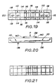
- a 200 mm ⁇ 100 mm ⁇ 1000 mm concrete panel which had a pair of glass fiber meshes 110 and 110 placed horizontally within it was prepared as illustrated in FIGS. 19 and 20, in which one mesh is shown by the solid line for illustration purposes.
- the pitch of each of the meshes was 100 mm and length and width thereof were 600 mm and 200 mm respectively.
- the projected portions 116 of crosswise elements 112 and longitudinal elements 114 of the meshes were 50 mm long. Although the outer ends 118 and 118 of lengthwise elements 114 and 114 of each mesh were continuous via connecting element 120, it is believed that this resulted in no substantial influence on the experimental results.
- the two meshes were overlapped 150 mm at their inner end portions in contact with each other. The distance from the lower face of the lower mesh 110 to the bottom of the concrete panel was 20 mm.
- Each of the glass fiber meshes 110 and 110 has substantially the same cross-sectional structure even in crossing portions thereof as the grid member 30 shown in FIGS. 1 to 3. That is, each of both crosswise elements 112 and the lengthwise elements 114 of the meshes had vertically stacked eight rows of glass fiber rovings bonded with a vinyl ester resin, each row consisting of four rovings.
- the vinyl ester resin was sold by Nippon (Japan) Upica, Japan under the trade designation "8250". Both the lengthwise and crosswise elements have substantially equal cross-sectional areas of about 10 mm ⁇ 10 mm.
- Each roving consisted of about 2,100 glass fiber filaments, each of which had a diameter about 23 micrometers, a density of 2.55 g/cm3 and denier of 19,980.
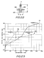
- Properties of the lengthwise and crosswise elements of the glass fiber meshes are given in TABLE 1. The average tensile strength of these elements was determined by stretching 200 mm long test pieces with their opposite end portions 50 mm long, cramped through a glass fiber roving cloth with chucks. The average strength of the crossing portions of the grid was determined by the use of cross-shaped test pieces 129 cut from the grid, as shown in FIG. 22, having a width 80 mm and a length 90 mm.
- Each test piece was fitted at its one longitudinal leg 30 mm long into a hole 130 formed in a base 132 of a test machine. Static loads were vertically applied to the upper end of the other longitudinal leg 50 mm long. The strength of the crossing portions is defined as a shear fracture load of the crosswise legs / the effective cross-sectional area of the legs. The results are also given in Table 1. The properties of the concrete used are set forth in Table 2.
- the concrete panel thus prepared was cured and then placed on a pair of parallel supporting rods 136 and 136 for determining its load-strain behavior so that each rod 136 was located 280 mm away from the center of the panel. Then, a depressing plate 138 having a pair of parallel depressing rods 140 and 140 welded at its bottom face 280 mm away from each other was placed on the upper face of the concrete panel so that each depressing rod 140 was located 140 mm away from the center of the panel. Thereafter, static loads were applied to the depressing plate 138 and the results are plotted with the solid line in FIG. 23. It was noted that longitudinal elements 114 were fractured at the point P1.
- Another concrete panel having a pair of carbon fiber grids placed within it was prepared and cured.
- the shape and size of the concrete panel and the grids were substantially the same as those in Example 1 and the carbon fiber grids were disposed in the concrete panel also in the same manner as in FIGS. 19 and 20.
- each of the lengthwise and crosswise elements was substantially the same as that of each of the lengthwise and crosswise elements in Example 1 even in crossing portions except that each row of carbon fiber rovings included five rovings, each containing 10,000 carbon monofilaments having about 8 micrometers diameter.
- the carbon fiber roving elements were bonded with the same vinyl ester resin as in Example 1.
- the properties of the elements of the grid were determined by the same procedures in Example 1 and the results are given in Table 1.
- the carbon grid reinforced concrete panel underwent the same load-strain test as in Example 1 and the results are also plotted with the broken line in FIG. 23. It was noted that longitudinal elements were fractured at the point P2.
- a steel grid reinforced concrete panel was prepared as illustrated in FIG. 21 and had the same size and structure as in Example 1 except that the longitudinal outer end portions of lengthwise elements of each grid were straight and not jointed together, and that the lengthwise and crosswise elements had a diameter 9.53 mm.
- the steel grid reinforced concrete panel was subjected to the same load-strain test as in Example 1 and the results are also plotted with the phantom line in FIG. 23. It was noted that welded points of the crossing portions of the lengthwise and crosswise elements were fractured at the point P3.
Description
- The present invention relates to a concrete reinforcing unit which is suitably used as a replacement of the reinforcing steel in various concrete constructions.
- For example, girders and columns of a building have concrete reinforcements embedded in concrete, including steel frameworks having main reinforcements wound with additional reinforcements for shearing such as hoops, stirrups and spiral hoops.
- These steel reinforcements are widely used for various concrete constructions since their cost is relatively small and they have sufficient strength. With recent progress in architecture and civil engineering, there are, however, the following problems to be solved:
- (1) It is difficult to provide large-sized reinforcing units since they are poor in transportability and workability on the construction site due to their considerable weight;
- (2) Binding, welding and pressure welding of steel reinforcements are rather laborious and thus take a considerable part of the construction period for concrete construction;
- (3) It is very hard to enhance accuracy in assembling steel reinforcements since the bending of large diameter reinforcement bars is difficult on the construction site;
- (4) Steel reinforcements necessitate control for preventing corrosion during storage and are further liable to cause breaking away of the concrete due to corrosion thereof; and
- (5) Considerable differences in the covering depth of concrete between the main reinforcements and reinforcements for shearing occur in columns and girders of concrete construction such, as a building, since main reinforcements and reinforcements for shearing are embedded in the concrete in a crosswise manner to form different levels between them;
- DE-A-3 032 533 discloses a mesh made of a synthetic resin and glass fibers impregnated therein, which may be used for reinforcing plastic items, concrete items, and the like.
- GB-A-2 070 098 discloses a panel structure in the form of a grid made from a mouldable synthetic resin reinforced by fibers laid in rows crossing each other.
- Accordingly, it is an object of the present invention to provide a concrete reinforcing unit possessing an increase in the mechanical strength when compared with known units.
- The present invention provides a reinforcing unit for use in a concrete structure comprising two or more systems of elongate reinforcing elements, the elements in each system being parallel to one another, which cross at a number of crossing portions, so as to form at least one planar grid member, each of the reinforcing elements comprising longitudinally extending textile filamentary material embedded in a resin matrix, characterised in that the filamentary material is in the form of stacked parallel rows each of which contain a plurality of parallel filaments aligned side by side, the rows in one system of reinforcing elements interleaving with the rows of the other system(s) of reinforcing elements at their crossing portions, the crossing portions of the reinforcing elements being press-formed so as to be of substantially equal thickness with the non-crossing portions.
- For convenience the elongate reinforcing elements and their textile filamentary material components will be referred to as first and second reinforcing elements and first and second textiles as appropriate.
- The first reinforcing elements and the second reinforcing elements may have a substantially rectangular cross-section.
- In practice, the grid member may be substantially two-dimensional and be embedded in the concrete so that it is parallel with a surface of the concrete.
- Further, the grid member may be used in the number of at least two, and adjacent grid members may be disposed to overlap each other at peripheral portions thereof.
- Preferably, the first textiles are each formed into at least one structure of a tow, roving, strand, yarn, thread, sennit and braid, and are made of at least one fiber selected from the group consisting of a glass fiber, carbon fiber, aramid fiber, boron fiber, ceramic fiber, and metallic fiber.
- The first resin matrixes are preferably made of a substance selected from the group consisting of an epoxy resin, unsaturated polyester resin, vinyl ester resin, polyurethane resin, diallylphthalate resin, phenolic plastic, polyacetal, saturated polyester resin, polyamide resin, ploystyrene resin, polycarbonate resin, polyvinyl chloride resin, polyethylene resin, polypropylene resin and acrylic resin.
- Preferably, the first reinforcing elements and the second reinforcing elements each contain about 10 to about 90 % by volume of the first textiles and about 90 to about 10 % by volume of the first resin.
- In another preferred form, the first reinforcing elements and the second reinforcing elements each contain about 30 to about 70 % by volume of a glass fiber and about 70 to about 30 % by volume of a vinyl ester resin.
- In still another preferred form, the first reinforcing elements and the second reinforcing elements each contain about 20 to 60 % by volume of a carbon fiber and about 80 to about 40 % by volume of a vinyl ester resin.
- Preferably, the concrete reinforcing unit may further comprise: at least three longitudinal parallel reinforcing elements disposed in a three-dimensional manner; and second attaching means for attaching said longitudinal parallel reinforcing elements to the first reinforcing elements and the second reinforcing elements, and wherein the first reinforcing elements and second reinforcing elements cross corresponding longitudinal reinforcing elements at second crossing portions and are attached to the corresponding longitudinal reinforcements at second crossing portions with the second attaching means. Such a construction provides a three-dimentional concrete reinforcing unit having an excellent workability, transportability and a relatively large size as compared to the prior art concrete reinforcement. Further, such a concrete reinforcing unit is excellent for corrosion resistance and is hence useful in concrete construction.
- In a further preferred form, the longitudinal reinforcing elements may each comprise: at least one row of second parallel textiles; and a second resin matrix, nade of a second resin, for integrally bonding said row of the second textiles. The textile rows of each of a corresponding first reinforcing element, a corresponding second reinforcing element and a corresponding longitudinal reinforcing element may be alternatively stacked at each of said second crossing portions. The second attaching means may be one of the first resin and the second resin. With such a construction, the concrete reinforcing unit may have the first reinforcement elements, the second reinforcement elements and the longitudinal reinforcement elements placed substantially at an equal level around the second crossing portions Thus, substantially uniform concrete covering depth may be achieved for concrete construction.
- Further, the first reinforcing elements and the second reinforcing elements preferably extend between two adjacent longitudinal reinforcing elements so that the first reinforcing elements and the second reinforcing elements each generally define a spiral in the overall shape thereof.
- The second textiles may be each formed into at least one structure of a tow, roving, strand, yarn, thread, sennit and braid, and wherein the second textiles are each made of at least one fiber selected from the group consisting of a glass fiber, carbon fiber, aramid fiber, boron fiber, ceramic fiber, and metallic fiber. Further, the second resin matrixes may each be made of a substance selected from the group consisting of an epoxy resin, unsaturated polyester resin, vinyl ester resin, polyurethane resin, diallylphthalate resin, phenolic plastic, polyacetal, saturated polyester resin, polyamide resin, ploystyrene resin, polycarbonate resin, polyvinyl chloride resin, polyethylene resin, polypropylene resin and acrylic resin.
- The longitudinal reinforcing elements may each contain about 10 to about 90 % by volume of the second textiles and about 90 to about 10 % by volume of the second resin. Preferably, the longitudinal reinforcing elements each contain about 30 to about 70 % by volume of a glass fiber and about 70 to about 30 % by volume of a vinyl ester resin. In another preferred form, the longitudinal reinforcing elements each contain about 20 to 60 % by volume of a carbon fiber and about 80 to about 40 % by volume of a vinyl ester resin.
- The invention will now be described by way of example with reference to the accompanying drawings in which:
- FIG. 1 is a perspective view of a concrete reinforcing unit according to the present invention;
- FIG. 2 is an enlarged cross-section of each of the first reinforcing elements and the second reinforcing elements in FIG. 1;
- FIG. 3 is an enlarged cross-section of a crossing portion in FIG. 1;
- FIG. 4 is a plan view of an apparatus for fabricating the concrete reinforcing unit in FIG. 1, with the first and the second reinforcing elements set in it;
- FIG. 5 is a side view of the apparatus in FIG. 4 with a depressing plate placed in position;
- FIG. 6 is an illustrative view demonstrating how to interweave resin-impregnated textile rows to produce the concrete reinforcing unit in FIG. 1;
- FIG. 7 is an enlarged cross-sectional view of one of the resin-impregnated textile bundles before it is depressed with the depressing plate in FIG. 5;
- FIG. 8 is an enlarged cross-sectional view of the depressed textile bundle in FIG. 7;
- FIG. 9 is a perspective view of a concrete reinforcing unit having a lattice girder structure according to the present invention;
- FIG. 10 is an enlarged partial view of the concrete reinforcing unit in FIG. 9;
- FIG. 11 is an enlarged cross-section of each of the spiral reinforcing elements and the longitudinal reinforcing elements;
- FIG. 12 is an enlarged cross-section taken along the line XII-XII in FIG. 10;
- FIG. 13 is an enlarged cross-section taken along the line XIII-XIII in FIG. 10;
- FIG. 14 is a front view of an apparatus for fabricating the concrete reinforcing unit in FIG. 9;
- FIG. 15 is an enlarged view taken along the line XV-XV in FIG. 14;
- FIG. 16 is an enlarged partial view of the apparatus in FIG. 14 with the spiral elements and the longitudinal elements crossing each other;
- FIG. 17 is an enlarged view, partly in axial section, of the hooking portion of the apparatus in FIG. 14;
- FIG. 18 is an illustration with a two-dimensional expansion as to how to interweave the spiral elements and the longitudinal elements;
- FIG. 19 is a plan view of a concrete panel used in Example 1, the upper grid shown by the solid lines for illustration purpose;
- FIG. 20 is a side view of the concrete panel in FIG. 19;
- FIG. 21 is a plan view of another concrete panel used in Comparative Test, the upper grid shown by the solid lines for illustration purposes;
- FIG. 22 is a front view of a test piece of Example 1 placed in a test machine; and
- FIG. 23 is a graph showing results of static load tests.
- FIGS. 1 to 3 illustrate a
concrete reinforcing unit 30 in the shape of a grid according to the present invention. The reinforcingunit 30 is suitably used as a reinforcement which is embedded in concrete to form a wall or a floor of a building. Thereinforcing unit 30 includes a plurality of firstparallel reinforcing elements 32 and a plurality of second parallel reinforcingelements 34 crossing the first parallel reinforcing elements to form a grid, all the first and secondreinforcing elements elements 32 is five and the number of the second reinforcingelements 34 is four. As illustrated in FIG. 2, each of the first and second reinforcingelements textiles 36 which are bonded together through aresin matrix 38. Eachtextile row 40 has fourparallel textiles 36, rovings in this embodiment, contacting or nearly contacting adjacent textile ortextiles 36 of thesame row 40. Crossingportions 42 of both the first and second reinforcingelements textile rows 40 of the first reinforcingelements 32 and eighttextile rows 40 of the second reinforcingelements 34 are alternatively stacked, so that the crossingportion 42 has 16 rows of textiles in total in this embodiment. However, the number oftextile rows 40 in each crossingportion 42 may be two or more. Each crossingportion 42 and non-crossing portions of the first and second reinforcingelements unit 30 are each at an equal level. The upper and lower faces of the reinforcingunit 30 may be roughened for enhancing adhesive strength to the resin of theresin matrix 38. - In the present invention, the structure of the
textiles 36 include, for example, a tow, roving, strand, yarn, thread and braiding
Textiles 36 are, according to the present invention, made of: for example, a glass fiber; carbon fiber; aramid fiber; boron fiber; ceramic fiber such as made of alumina, silica and titanium oxide; metallic fiber such as stainless steel fiber; and combination thereof. Preferably, glass fiber and carbon fiber are used due to relatively light weight and high strength. - The
resin matrix 38 which bondstextile rows 40 together is, according to the present invention, preferably made of a vinyl ester resin due to its excellent adhesiveness totextiles 36 and sufficient strength but the resin forming theresin matrix 38 depends on the kind of textiles used. Use may be made of other synthetic resins such as an epoxy resin, unsaturated polyester resin, polyurethane resin, diallylphthalate resin, phenolic plastic, polyacetal, saturated polyester resin, polyamide resin, ploystyrene resin, polycarbonate resin, polyvinyl chloride resin, polyethylene resin, polypropylene resin and acrylic resin. - The reinforcing
unit 30, according to the present invention, generally contains about 10 to about 90 % by volume of the textile 36 but the ratio is selected in view of the kind and strength of thetextiles 36 and use of the reinforcing unit. When a glass fiber is used for thetextiles 36 and a vinyl ester resin is used for theresin matrix 38, the reinforcingunit 30 for building constructions includes preferably about 30 to about 70 % by volume of the glass fiber. Below about 30 %, strength of the resultant reinforcing unit reduces and beyond about 70 %, the resulting reinforcing unit is costly in the glass fiber. When a pitch carbon fiber and a vinyl ester resin are used, the reinforcing unit includes preferably about 20 to about 60 % by volume of the pitch carbon fiber. Below about 20 % by volume of the pitch carbon fiber, the resulting reinforcing unit is rather inferior in strength, and above about 60 %, cost performance of the carbon fiber is considerably reduced although the reinforcing unit has relatively high strength. - The reinforcing
unit 30, according to the present invention, may be produced by means of an apparatus as illustrated in FIGS. 4 and 5, although in this apparatus a grid reinforcing unit having five first reinforcingelements 32 and nine second reinforcingelements 34 is to be fabricated. In FIGS. 4 and 5, thereference numeral 50 designates a rectangular base plate having chamfered upper edges 52. Taper pins 54 are mounted in the number of 28 at their smaller diameter ends to lateral faces 56 of thebase plate 50 so that they are located to correspond to pitches of the first and second reinforcingelements - In producing the reinforcing
unit 30, arow 60 ofcontinuous textiles 62, which are impregnated with a resin for forming theresin matrix 38, are hooked around eachpin 54 to extend it tightly between facingpins 54, for example, in a longitudinal direction L and then in a transverse direction T in the order I-XXVIII as shown in FIG. 4. When a grid member having more than twotextile rows 40 is made as in this embodiment, the row of thecontinuous textiles 62 is returned from the pin XXVIII to the pin I and then the operation described above is repeated.Adjacent textile rows portions 42 cross each other. That is, textile rows example 1 of the first and second reinforcingelements 32 an 34 are alternatively stacked at the crossingportions 42. FIG. 6 illustrates one crossingportion 42 of fourrows 60 oftextiles 62 impregnated with a resin, eachtextile row 60 including fourtextiles 62, rovings in this embodiment. The fourtextile rows 60 are stacked in the alphabetical order A-D as illustrated. Thus, in the reinforcingunit 30 in FIGS. 1 to 3, the above-stated operation which consists of four steps A to D is repeated four times since each crossingportion 42 thereof includes 16 rows vertically stacked. In this process sufficient tension must be applied to thetextiles 62 to keep them tight. This process is manually carried out, but may be achieved automatically by means of a numerically controlled machine which is actuated on a predetermined program describing a two-dimensional pattern of thegrid member 30. Then, the grid member thus formed (FIG. 7) is depressed by means of adepressing plate 64 as shown in FIG. 8 for providing a uniform thickness to it. When the resin is set, each of the first and the second reinforcingelements pins 54 and then removed from thebase plate 50. Thus, thegrid member 30 is completed. It is to be noted that the base plate and the depressing plate should have poor adhesive properties to the resin. In this embodiment, the working faces of thebase plate 50 and thedepressing plate 64 are coated with Teflon resin and thepins 54 are applied with a wax for this purpose. - Rough surfaces may be formed in the upper or lower faces of the reinforcing unit by providing irregularity to the lower face of the depressing unit or the upper face of the base plate. The rough faces of the reinforcing unit enhance its adhesive property to the concrete in which it is embedded.
- Although two adjacent first reinforcing
elements elements grid member 30 may have bias reinforcing elements crossing both the first and second reinforcingelements grid member 30 has a constant pitch, but a portion of thegrid member 30 may have a pitch larger than the other portion, in which case a rectangular pattern may be defined. - For producing a grid reinforcing unit, a plurality of separate first and second reinforcing elements previously set may be attached. In this case, the separate first and second reinforcing elements are bound with strings or fastened with bolts and nuts at the crossing portions. Alternatively, they may be bonded or attached by melting.
- FIGS. 9 and 10 illustrate another
concrete reinforcement unit 70 having a lattice girder structure according to the present invention. Thereinforcement unit 70 is used as a reinforcement for a column or a beam of a concrete building. Thereinforcement unit 70 includes four parallel longitudinal reinforcingelements 72, four firstspiral reinforcing elements 74 as lattice bars and four secondspiral reinforcing elements 76 as the other lattice bars. The longitudinal reinforcingelements 72 are disposed in a three-dimensional manner with an equal spacing. The firstspiral reinforcing elements 74 and the secondspiral reinforcing elements 76 spirally extend around the four longitudinal reinforcingelements 72 in opposite directions, thus forming crossing portions A on longitudinal reinforcingelements 72 and crossing portions B between adjacent two longitudinal reinforcingelements elements 72 and thespiral reinforcing elements elements grid member 30, but it includes fourtextile rows 80 and each row consists of fivetextiles 36. The textiles of theseelements grid member 30 and are contained in aresin matrix 82 which may also be made of the same material as theresin matrix 38 of the preceding embodiment. In this embodiment, thetextiles 36 of each of the longitudinal reinforcingelements 72 and the first and secondspiral reinforcing elements resin matrix 82 of the same resin. The longitudinal reinforcing elements and the first and second spiral reinforcing elements are substantially equal in the ratio of the textiles over the resin to those of the first embodiments. - In each of the crossing portions A,
textile rows 80 of a corresponding longitudinal reinforcingelement 72 and corresponding first and secondspiral reinforcing elements textile rows 80 of the first and the secondspiral reinforcing elements portions 42 of the reinforcingelements textile rows 80 stacked is eight with each row including fivetextiles 36. Thickness T of each of the longitudinal reinforcingelements 72 and the first and secondspiral reinforcing elements - The
concrete reinforcing unit 70 is fabricated by means of an apparatus illustrated in FIGS. 14 and 15, in which thereference numeral 90 designates a rotation shaft. Opposite ends of therotation shaft 90 are rotatably supported on a pair of bearing stands 92 through ball bearings not shown. Therotation shaft 90 has six sets of equidistant supportingarms 94. Each supporting arm set includes four supportingarms 94 projecting radially outwardly from therotation shaft 90 at equal angular intervals, i.e., 90°. The supportingarms 94 are disposed so that they are axially aligned for forming four axial rows of supportingarms 94 as shown in FIG. 15. As best shown in FIG. 17, each supportingarm 94 includes a supportingpipe 96 fixed at its proximal end to therotation shaft 90, anut member 98 rotatably supported on the distal end of the supportingpipe 96 and a two-pronged hook member 100 threaded to thenut member 98. Each supportingpipe 96 has an innercircular flange 102 formed by bending its distal end radially inward and thecircular flange 102 fits in acircular groove 104 formed in an associatedrotatory nut member 98 for supporting thenut member 98. The two-pronged hook members 100 each have astem portion 106 and a two-pronged hook portion 108 formed integrally with one end of thestem portion 106. Thestem portion 106 of eachhook member 100 is threaded with thenut member 98 and thus rotation of thenut member 98 axially moves thehook member 100 by preventing rotation of the latter. - In production, a
row 80 of continuous resin-impregnatedtextile 36 is prepared by passing it through a bath of a resin, vinyl ester resin in this embodiment. Then, it is hooked under tension manually inhook portions 108 ofhook members 100 of the supportingarms 94 in sequence to define the reinforcingunit 70. FIG. 18 illustrates a sequence of hooking thetextile row 80 in development elevation, in which the two phantom lines indicate the same portion to form a longitudinal reinforcingelement 72 and the arrows show the directions of passing of thetextile row 80. The hooking of thetextile row 80 starts from a supportingarm 94 which is for example one support arm, designated by O, of the leftmost support arm set in FIG. 14. Thetextile row 80 passes through the hookingportion 108 of each hookingmember 100 in the numeric sequence given in FIG. 18 and then returns to its start point O. FIG. 16 illustrates a crossing portion A at this time. In this embodiment this procedure is repeated four times. Thetextile row 80 thus extended must be kept tight until the impregnated resin is set. After setting of the resin, portions of the continuous textile, shown by the broken lines in FIG. 18, are cut and then thenut member 98 of each supportingarm 94 is turned to retract thestem portion 106 of the hookingmember 100 toward the supportingpipe 96 for separating the crossing portions A thus set from associatedhook members 100. By this operation theconcrete reinforcement unit 70 is removed from the apparatus shown in FIG. 14 and completed. - The process above stated may be achieved automatically by means of a conventional numerically controlled machine which is actuated on a predetermined program describing a three-dimensional pattern of the
concrete reinforcing unit 70. - When the thickness of the longitudinal reinforcing
elements 72 must be larger, an additional resin-impregnated textile row or rows are added to the portions to form them. The three-dimensional concrete reinforcing unit according to the present invention is not limited to a square tubular, but may be in the shape of a rectilinear tube, quadrangular pyramid, hollow cylinder, cone or other like configurations. The pitch of the crossing portions A of a longitudinal reinforcing element orelements 72 may be partially changed. Further, the reinforcingunit 70 may have an additional reinforcing element or elements such as a hoop. - A 200 mm × 100 mm × 1000 mm concrete panel which had a pair of glass fiber meshes 110 and 110 placed horizontally within it was prepared as illustrated in FIGS. 19 and 20, in which one mesh is shown by the solid line for illustration purposes. The pitch of each of the meshes was 100 mm and length and width thereof were 600 mm and 200 mm respectively. The projected
portions 116 ofcrosswise elements 112 andlongitudinal elements 114 of the meshes were 50 mm long. Although the outer ends 118 and 118 oflengthwise elements element 120, it is believed that this resulted in no substantial influence on the experimental results. The two meshes were overlapped 150 mm at their inner end portions in contact with each other. The distance from the lower face of thelower mesh 110 to the bottom of the concrete panel was 20 mm. - Each of the glass fiber meshes 110 and 110 has substantially the same cross-sectional structure even in crossing portions thereof as the
grid member 30 shown in FIGS. 1 to 3. That is, each of both crosswiseelements 112 and thelengthwise elements 114 of the meshes had vertically stacked eight rows of glass fiber rovings bonded with a vinyl ester resin, each row consisting of four rovings. The vinyl ester resin was sold by Nippon (Japan) Upica, Japan under the trade designation "8250". Both the lengthwise and crosswise elements have substantially equal cross-sectional areas of about 10 mm × 10 mm. Each roving consisted of about 2,100 glass fiber filaments, each of which had a diameter about 23 micrometers, a density of 2.55 g/cm³ and denier of 19,980. Properties of the lengthwise and crosswise elements of the glass fiber meshes are given in TABLE 1. The average tensile strength of these elements was determined by stretching 200 mm long test pieces with theiropposite end portions 50 mm long, cramped through a glass fiber roving cloth with chucks. The average strength of the crossing portions of the grid was determined by the use ofcross-shaped test pieces 129 cut from the grid, as shown in FIG. 22, having awidth 80 mm and alength 90 mm. Each test piece was fitted at its onelongitudinal leg 30 mm long into ahole 130 formed in abase 132 of a test machine. Static loads were vertically applied to the upper end of the otherlongitudinal leg 50 mm long. The strength of the crossing portions is defined as a shear fracture load of the crosswise legs / the effective cross-sectional area of the legs. The results are also given in Table 1. The properties of the concrete used are set forth in Table 2. - The concrete panel thus prepared was cured and then placed on a pair of parallel supporting
rods rod 136 was located 280 mm away from the center of the panel. Then, adepressing plate 138 having a pair of paralleldepressing rods depressing rod 140 was located 140 mm away from the center of the panel. Thereafter, static loads were applied to thedepressing plate 138 and the results are plotted with the solid line in FIG. 23. It was noted thatlongitudinal elements 114 were fractured at the point P1. - Another concrete panel having a pair of carbon fiber grids placed within it was prepared and cured. The shape and size of the concrete panel and the grids were substantially the same as those in Example 1 and the carbon fiber grids were disposed in the concrete panel also in the same manner as in FIGS. 19 and 20.
- The cross-sectional structure of each of the lengthwise and crosswise elements was substantially the same as that of each of the lengthwise and crosswise elements in Example 1 even in crossing portions except that each row of carbon fiber rovings included five rovings, each containing 10,000 carbon monofilaments having about 8 micrometers diameter. The carbon fiber roving elements were bonded with the same vinyl ester resin as in Example 1. The properties of the elements of the grid were determined by the same procedures in Example 1 and the results are given in Table 1. The carbon grid reinforced concrete panel underwent the same load-strain test as in Example 1 and the results are also plotted with the broken line in FIG. 23. It was noted that longitudinal elements were fractured at the point P2.
- A steel grid reinforced concrete panel was prepared as illustrated in FIG. 21 and had the same size and structure as in Example 1 except that the longitudinal outer end portions of lengthwise elements of each grid were straight and not jointed together, and that the lengthwise and crosswise elements had a diameter 9.53 mm.
- The steel grid reinforced concrete panel was subjected to the same load-strain test as in Example 1 and the results are also plotted with the phantom line in FIG. 23. It was noted that welded points of the crossing portions of the lengthwise and crosswise elements were fractured at the point P3.

Claims (16)
- A reinforcing unit (30) for use in a concrete structure comprising two or more systems of elongate reinforcing elements (32,34), the elements in each system being parallel to one another, which cross at a number of crossing portions (42), so as to form at least one planar grid member, each of the reinforcing elements comprising longitudinally extending textile filamentary material (36) embedded in a resin matrix (38), characterised in that the filamentary material is in the form of stacked parallel rows (40) each of which contains a plurality of parallel filaments aligned side by side, the rows in one system of reinforcing elements interleaving with the rows of the other system(s) of reinforcing elements at their crossing portions, the crossing portions of the reinforcing elements being press-formed so as to be of substantially equal thickness with the non-crossing portions.
- A concrete reinforcing unit according to claim 1 wherein the reinforcing elements (32,34) have a substantially rectangular cross-section.
- A conrete reinforcing unit according to claim 1 or 2 wherein said grid member is substantially two-dimensional and is adapted to be embedded in the concrete so that the grid member is parallel with a surface of the concrete.
- A concrete reinforcing unit according to claim 3 comprising at least two adjacent grid members disposed to overlap each other at the peripheral portions thereof.
- A concrete reinforcing unit according to any of claims 1 to 4, wherein the textiles (36) are in the form of a tow, roving, strand, yarn, thread, sennit, twisted cord, or braid, and said textiles are made of at least one fiber selected from the group consisting of a glass fiber, carbon fiber, aramid fiber, boron fiber, ceramic fiber, and metallic fiber.
- A concrete reinforcing unit according to any of the preceding claims wherein the resin is selected from the group consisting of an epoxy resin, unsaturated polyester resin, vinyl ester resin, polyurethane resin, diallylphthalate resin, phenolic resin, polyacetal resin, saturated polyester resin, polyamide resin, polystyrene resin, polycarbonate resin, polyvinyl chloride resin, polyethylene resin, polypropylene resin and acrylic resin.
- A concrete reinforcing unit according to claim 6, wherein the first reinforcing elements (32) and the second reinforcing elements (34) are bonded, and then said fiber grid member is compressed for providing a uniform thickness.
- A concrete reinforcing unit as recited in claim 7, wherein said first reinforcing elements and said second reinforcing elements each contains about 30 to abut 70% by volume of a glass fiber and about 70 to about 30% by volume of a vinyl ester resin.
- A concrete reinforcing unit as recited in claim 7, wherein said first reinforcing elements and second reinforcing elements each contains about 20 to 60% by volume of a carbon fiber and about 80 to about 40% by volume of a vinyl ester resin.
- A concrete reinforcing unit as recited in any of the preceding claims comprising:
at least three longitudinal parallel reinforcing elements (72) disposed in a three-dimensional manner including stacked rows (80) of textiles (36) and a resin (82) for bonding integrally the rows (80) of the textiles (36) and attaching the textile rows of corresponding longitudinal reinforcing elements, corresponding first reinforcing elements (74) and corresponding second reinforcing elements (76) at second crossing portions where the textile rows cross alternately and interleaving with one another. - A concrete reinforcing unit as recited in claim 10, wherein said first reinforcing elements and the second longitudinal reinforcing elements extend between adjacent two longitudinal reinforcing elements so that the first reinforcing elements and the second reinforcing elements each define generally a spiral in an overall shape thereof.
- A concrete reinforcing unit as recited in claim 10 or 11, wherein said first textiles and said second textiles are each formed in at least one structure of a tow, roving, strand, yarn, thread, sennit, twisted cord, and braid, and wherein said first textiles and said second textiles are each made of at least one fiber selected from the group consisting of a glass fiber, carbon fiber, aramid fiber, boron fiber, ceramic fiber, and metallic fiber.
- A concrete reinforcing unit as recited in claim 12, wherein the resins used for bonding in textiles are selected from the group consisting of an epoxy resin, unsaturated polyester resin, vinyl ester resin, polyurethane resin, daillylphthalate resin, phenolic resin, polyacetal resin, saturated polyester resin, polyamide resin, polystyrene resin, polycarbonate resin, polyvinyl chloride resin, polyethylene resin, polypropylene resin and acrylic resin.
- A concrete reinforcing unit as recited in claim 12, wherein said first reinforcing elements (74) and sais second reinforcing elements (36) are bonded and compressed for providing a uniform thickness, and said longitudinal reinforcing elements (72) contain the second resin and the second textiles.
- A concrete reinforcing unit as recited in claim 14, wherein said first reinforcing elements, said second reinforcing elements and said longitudinal reinforcing elements each contain about 30 to about 70% by volume of a glass fiber and about 70 to about 30% by volume of a vinyl ester resin.
- A concrete reinforcing unit as recited in claim 14, wherein said first reinforcing elements, said second reinforcing elements and said longitudinal reinforcing elements each contain about 20 to 60% by volume of a carbon fiber and about 80 to about 40% by volume of a vinyl ester resin.
Applications Claiming Priority (4)
| Application Number | Priority Date | Filing Date | Title |
|---|---|---|---|
| JP60295751A JPH07100963B2 (en) | 1985-12-26 | 1985-12-26 | Concrete reinforcing member |
| JP295751/85 | 1985-12-26 | ||
| JP41197/86 | 1986-02-26 | ||
| JP61041197A JPH076254B2 (en) | 1986-02-26 | 1986-02-26 | Concrete reinforcing member |
Publications (3)
| Publication Number | Publication Date |
|---|---|
| EP0227207A2 EP0227207A2 (en) | 1987-07-01 |
| EP0227207A3 EP0227207A3 (en) | 1987-12-16 |
| EP0227207B1 true EP0227207B1 (en) | 1992-12-23 |
Family
ID=26380763
Family Applications (1)
| Application Number | Title | Priority Date | Filing Date |
|---|---|---|---|
| EP19860306037 Expired - Lifetime EP0227207B1 (en) | 1985-12-26 | 1986-08-05 | Concrete reinforcing unit |
Country Status (7)
| Country | Link |
|---|---|
| US (2) | US4706430A (en) |
| EP (1) | EP0227207B1 (en) |
| KR (1) | KR910008088B1 (en) |
| CN (1) | CN1010110B (en) |
| AU (1) | AU586378B2 (en) |
| CA (1) | CA1278699C (en) |
| DE (1) | DE3687345T2 (en) |
Cited By (3)
| Publication number | Priority date | Publication date | Assignee | Title |
|---|---|---|---|---|
| DE102017102366A1 (en) | 2017-02-07 | 2018-08-09 | Technische Universität Dresden | End anchorage of textile fabrics |
| DE102017120624A1 (en) * | 2017-09-07 | 2019-03-07 | Groz-Beckert Kg | Textile reinforcement arrangement, method for its production and separating and / or shaping device for use in this method |
| WO2019091832A1 (en) | 2017-11-10 | 2019-05-16 | CHT Germany GmbH | Fibre products with a coating made formed from aqueous polymer dispersions |
Families Citing this family (111)
| Publication number | Priority date | Publication date | Assignee | Title |
|---|---|---|---|---|
| JPS629940A (en) * | 1985-07-05 | 1987-01-17 | Shimizu Constr Co Ltd | Cylindrical body prepared with fiber-reinforced resin |
| EP0227207B1 (en) * | 1985-12-26 | 1992-12-23 | SHIMIZU CONSTRUCTION Co. LTD. | Concrete reinforcing unit |
| US4910076A (en) * | 1986-03-11 | 1990-03-20 | Mitsubishi Kasei Corporation | Fiber reinforced cement mortar product |
| IT1197387B (en) * | 1986-10-14 | 1988-11-30 | S I P A Spa | NON-WOVEN MAT OF HIGH-MODULE ACRYLIC CONTINUOUS FILAMENTS AND REINFORCED ITEMS WITH SUCH MAT |
| EP0297006B1 (en) * | 1987-06-26 | 1992-05-13 | SHIMIZU CONSTRUCTION Co. LTD. | Meshwork reinforced and pre-stressed concrete member, method and apparatus for making same |
| US4990390A (en) * | 1988-12-15 | 1991-02-05 | Shimizu Construction Co., Ltd. | Fiber grid reinforcement |
| DK720788D0 (en) * | 1988-12-23 | 1988-12-23 | Bms Kunstfiber | PROCEDURE FOR THE MANUFACTURING OF FIBER-ARMED NETS |
| AU4756590A (en) * | 1988-12-23 | 1990-08-01 | Bms Kunstfiber A/S | Compression mould for making a fibre reinforced element, e.g. a grating or a grid |
| DE4002062A1 (en) * | 1990-01-22 | 1991-07-25 | Sst Sicherheits Und Systemtech | FRP laminates for protective covers etc. - has FRP layers interleaved with thermoplastic polymer, greatly reducing risk of injuries from sec. splinters |
| US5186992A (en) * | 1990-03-12 | 1993-02-16 | The Bentley-Harris Manufacturing Company | Braided product and method of making same |
| DE4102332C2 (en) * | 1991-01-26 | 1998-07-02 | Frank Gmbh & Co Kg Max | Balcony connection |
| DE4121547A1 (en) * | 1991-06-28 | 1993-01-14 | Daimler Benz Ag | MULTILAYER INSULATION FILM |
| DE4213839C2 (en) * | 1992-04-29 | 2001-04-26 | Hilti Ag | Reinforcement of masonry components |
| JP2756069B2 (en) * | 1992-11-27 | 1998-05-25 | 株式会社ペトカ | Carbon fiber for concrete reinforcement |
| US5595795A (en) * | 1994-04-25 | 1997-01-21 | Netcom Technologies Corp. | Composite, preform therefore, method of making, and apparatus |
| US5763042A (en) * | 1994-06-28 | 1998-06-09 | Reichhold Chemicals, Inc. | Reinforcing structural rebar and method of making the same |
| JP2944024B2 (en) * | 1994-12-02 | 1999-08-30 | ショーボンド建設株式会社 | Reinforcement method for reinforced concrete structures |
| US5768847A (en) * | 1995-05-15 | 1998-06-23 | Policelli; Frederick J. | Concrete reinforcing devices, concrete reinforced structures, and method of and apparatus for producing such devices and structures |
| US5650220A (en) * | 1995-05-26 | 1997-07-22 | Owens-Corning Fiberglas Technology, Inc. | Formable reinforcing bar and method for making same |
| US5888608A (en) * | 1995-08-15 | 1999-03-30 | The Board Of Trustees Of The Leland Stanford Junior University | Composite grid/frame structures |
| US5836715A (en) | 1995-11-19 | 1998-11-17 | Clark-Schwebel, Inc. | Structural reinforcement member and method of utilizing the same to reinforce a product |
| DE19617315A1 (en) * | 1996-04-30 | 1997-11-06 | Gepro Ing Gmbh | Tensile element used to reinforce earth structures |
| CA2267075C (en) | 1996-10-07 | 2004-05-18 | Mark A. Kaiser | Reinforced composite product and apparatus and method for producing same |
| DE19704241A1 (en) * | 1997-02-05 | 1998-08-06 | Engelbert Germar | Device to reinforce floors of buildings, etc. |
| US6143412A (en) * | 1997-02-10 | 2000-11-07 | President And Fellows Of Harvard College | Fabrication of carbon microstructures |
| US6786420B1 (en) | 1997-07-15 | 2004-09-07 | Silverbrook Research Pty. Ltd. | Data distribution mechanism in the form of ink dots on cards |
| US6803989B2 (en) * | 1997-07-15 | 2004-10-12 | Silverbrook Research Pty Ltd | Image printing apparatus including a microcontroller |
| US6702417B2 (en) * | 1997-07-12 | 2004-03-09 | Silverbrook Research Pty Ltd | Printing cartridge with capacitive sensor identification |
| US6618117B2 (en) * | 1997-07-12 | 2003-09-09 | Silverbrook Research Pty Ltd | Image sensing apparatus including a microcontroller |
| US6547364B2 (en) * | 1997-07-12 | 2003-04-15 | Silverbrook Research Pty Ltd | Printing cartridge with an integrated circuit device |
| US6624848B1 (en) * | 1997-07-15 | 2003-09-23 | Silverbrook Research Pty Ltd | Cascading image modification using multiple digital cameras incorporating image processing |
| AUPO850097A0 (en) * | 1997-08-11 | 1997-09-04 | Silverbrook Research Pty Ltd | Image processing method and apparatus (art31) |
| US6918654B2 (en) * | 1997-07-15 | 2005-07-19 | Silverbrook Research Pty Ltd | Ink distribution assembly for an ink jet printhead |
| US6879341B1 (en) | 1997-07-15 | 2005-04-12 | Silverbrook Research Pty Ltd | Digital camera system containing a VLIW vector processor |
| AUPO798697A0 (en) * | 1997-07-15 | 1997-08-07 | Silverbrook Research Pty Ltd | Data processing method and apparatus (ART51) |
| US7284843B2 (en) | 1997-07-15 | 2007-10-23 | Silverbrook Research Pty Ltd | Ink distribution assembly for an ink jet printhead |
| US6985207B2 (en) * | 1997-07-15 | 2006-01-10 | Silverbrook Research Pty Ltd | Photographic prints having magnetically recordable media |
| US7724282B2 (en) * | 1997-07-15 | 2010-05-25 | Silverbrook Research Pty Ltd | Method of processing digital image to correct for flash effects |
| AUPO802797A0 (en) * | 1997-07-15 | 1997-08-07 | Silverbrook Research Pty Ltd | Image processing method and apparatus (ART54) |
| US7044589B2 (en) * | 1997-07-15 | 2006-05-16 | Silverbrook Res Pty Ltd | Printing cartridge with barcode identification |
| US7050143B1 (en) * | 1998-07-10 | 2006-05-23 | Silverbrook Research Pty Ltd | Camera system with computer language interpreter |
| US7110024B1 (en) * | 1997-07-15 | 2006-09-19 | Silverbrook Research Pty Ltd | Digital camera system having motion deblurring means |
| US6820968B2 (en) * | 1997-07-15 | 2004-11-23 | Silverbrook Research Pty Ltd | Fluid-dispensing chip |
| AUPO797897A0 (en) * | 1997-07-15 | 1997-08-07 | Silverbrook Research Pty Ltd | Media device (ART18) |
| US6727948B1 (en) * | 1997-07-15 | 2004-04-27 | Silverbrook Research Pty Ltd | Utilizing autofocus information for image processing in a digital camera |
| US20040119829A1 (en) | 1997-07-15 | 2004-06-24 | Silverbrook Research Pty Ltd | Printhead assembly for a print on demand digital camera system |
| US6690419B1 (en) | 1997-07-15 | 2004-02-10 | Silverbrook Research Pty Ltd | Utilising eye detection methods for image processing in a digital image camera |
| US7714889B2 (en) * | 1997-07-15 | 2010-05-11 | Silverbrook Research Pty Ltd | Digital camera using exposure information for image processing |
| AUPO850597A0 (en) | 1997-08-11 | 1997-09-04 | Silverbrook Research Pty Ltd | Image processing method and apparatus (art01a) |
| AUPO801997A0 (en) * | 1997-07-15 | 1997-08-07 | Silverbrook Research Pty Ltd | Media processing method and apparatus (ART21) |
| FI973721A0 (en) * | 1997-09-18 | 1997-09-18 | Ahlstrom Glassfibre Oy | Multiaxialarmeringsvaevnad |
| US6256957B1 (en) * | 1998-08-10 | 2001-07-10 | Thomas L. Kelly | Scrim reinforced lightweight concrete roof system |
| AUPP702098A0 (en) | 1998-11-09 | 1998-12-03 | Silverbrook Research Pty Ltd | Image creation method and apparatus (ART73) |
| US6231946B1 (en) | 1999-01-15 | 2001-05-15 | Gordon L. Brown, Jr. | Structural reinforcement for use in a shoe sole |
| AUPQ056099A0 (en) | 1999-05-25 | 1999-06-17 | Silverbrook Research Pty Ltd | A method and apparatus (pprint01) |
| US6345483B1 (en) * | 1999-09-17 | 2002-02-12 | Delta-Tie, Inc. | Webbed reinforcing strip for concrete structures and method for using the same |
| MXPA02006662A (en) | 2000-01-05 | 2004-09-10 | Saint Gobain Technical Fabrics | Smooth reinforced cementitious boards and methods of making same. |
| WO2001051731A1 (en) | 2000-01-13 | 2001-07-19 | The Dow Chemical Company | Small cross-section composites of longitudinally oriented fibers and a thermoplastic resin as concrete reinforcement |
| JP2004511683A (en) * | 2000-01-13 | 2004-04-15 | ダウ グローバル テクノロジーズ インコーポレイティド | Reinforcing bars for concrete structures |
| BE1013858A3 (en) * | 2000-11-29 | 2002-10-01 | Goossens Marcel Florentine Luc | Construction element comprising mixture of wood particles and cement, useful as beam or pile, contains reinforcing mesh |
| US6820387B2 (en) * | 2001-08-13 | 2004-11-23 | Abraham Sacks | Self-stiffened welded wire lath assembly |
| DE10161728A1 (en) * | 2001-12-15 | 2003-06-18 | Andreas Seiler | The concrete fence component is reinforced with a mat of woven glass fibers, or single aligned glass fibers |
| US6729090B2 (en) * | 2002-03-06 | 2004-05-04 | Oldcastle Precast, Inc. | Insulative building panel with transverse fiber reinforcement |
| US7627997B2 (en) | 2002-03-06 | 2009-12-08 | Oldcastle Precast, Inc. | Concrete foundation wall with a low density core and carbon fiber and steel reinforcement |
| US6701683B2 (en) * | 2002-03-06 | 2004-03-09 | Oldcastle Precast, Inc. | Method and apparatus for a composite concrete panel with transversely oriented carbon fiber reinforcement |
| US6898908B2 (en) * | 2002-03-06 | 2005-05-31 | Oldcastle Precast, Inc. | Insulative concrete building panel with carbon fiber and steel reinforcement |
| US7100336B2 (en) | 2002-03-06 | 2006-09-05 | Oldcastle Precast, Inc. | Concrete building panel with a low density core and carbon fiber and steel reinforcement |
| AU2003257312A1 (en) * | 2002-08-12 | 2004-02-25 | Saltech Inc. | Composite structural member |
| US20050055922A1 (en) * | 2003-09-05 | 2005-03-17 | Mohammad Shamsai | Prefabricated cage system for reinforcing concrete members |
| US6973864B1 (en) * | 2003-12-19 | 2005-12-13 | The Cooper Union For The Advancement Of Science And Art | Protective structure and protective system |
| US7562613B2 (en) * | 2003-12-19 | 2009-07-21 | The Cooper Union For The Advancement Of Science And Art | Protective structure and protective system |
| US20090120025A1 (en) * | 2004-10-05 | 2009-05-14 | Halil Sezen | Prefabricated concrete reinforcement system |
| US20070144093A1 (en) * | 2005-07-06 | 2007-06-28 | Messenger Harold G | Method and apparatus for fabricating a low density wall panel with interior surface finished |
| WO2007108559A1 (en) * | 2006-03-23 | 2007-09-27 | Kirin Pharma Kabushiki Kaisha | Agonistic antibody directed against human thrombopoietin receptor |
| US20080104913A1 (en) * | 2006-07-05 | 2008-05-08 | Oldcastle Precast, Inc. | Lightweight Concrete Wall Panel With Metallic Studs |
| US20090228463A1 (en) * | 2008-03-10 | 2009-09-10 | Cramer Richard D | Method for Searching Compound Databases Using Topomeric Shape Descriptors and Pharmacophoric Features Identified by a Comparative Molecular Field Analysis (CoMFA) Utilizing Topomeric Alignment of Molecular Fragments |
| US20100075074A1 (en) * | 2008-08-15 | 2010-03-25 | Wilson Erich A | Collapsible Mandrel Tools and Associated Methods for Fabrication of Wound Composite Articles |
| GB0903678D0 (en) * | 2009-03-04 | 2009-04-15 | Univ Ulster | Composite concrete article and method of manufacture thereof |
| GB0905951D0 (en) | 2009-04-06 | 2009-05-20 | Univ Ulster | Method of manufacture of a composite concrete article |
| NO333023B1 (en) * | 2010-03-03 | 2013-02-18 | Reforcetech Ltd | Reinforcement system and method for building concrete structures. |
| US9434464B1 (en) * | 2010-07-15 | 2016-09-06 | The Boeing Company | Window exhibiting reduced sound transmission and method of making the same |
| SE536197C2 (en) * | 2010-10-12 | 2013-06-25 | Svensk Cellarmering Fabrik Ab | Reinforcing elements for casting comprising annular portions and reinforcement including such reinforcing elements |
| US9926703B1 (en) | 2010-10-15 | 2018-03-27 | Constructive, Llc | Prefabricated masonry wall panels |
| US9932737B1 (en) | 2010-10-15 | 2018-04-03 | Constructive , Llc | Prefabricated masonry lintels |
| US10544583B2 (en) | 2010-10-15 | 2020-01-28 | Constructive, L.L.C. | Prefabricated masonry walls |
| WO2013054359A2 (en) * | 2011-10-11 | 2013-04-18 | Valagam Rajagopal Raghunathan | A lattice tower and its fabrication utilizing the composite wraping method |
| AU2013220923B2 (en) * | 2012-02-17 | 2017-09-07 | Lifting Point Pty Ltd | Height adjustable shipping container |
| HUE027065T2 (en) | 2012-05-23 | 2016-08-29 | Groz Beckert Kg | Textile-reinforced concrete element |
| US9951521B2 (en) * | 2012-05-31 | 2018-04-24 | Wayne State University | Self-confining ceramic articles using advanced material reinforcements and method of manufacture |
| US9145679B2 (en) | 2012-06-14 | 2015-09-29 | Xtreme Manufacturing, Llc | Form assembly for concrete slabs and methods of assembling same |
| US9139937B2 (en) | 2012-11-28 | 2015-09-22 | Milliken & Company | Method of strengthening existing structures using strengthening fabric having slitting zones |
| US9708816B2 (en) | 2014-05-30 | 2017-07-18 | Sacks Industrial Corporation | Stucco lath and method of manufacture |
| SE539746C2 (en) * | 2015-07-08 | 2017-11-14 | Innovativ Plast I Väst Ab | Stackable wall spacer for supporting a reinforcement grid inconcrete constructions |
| US9752323B2 (en) | 2015-07-29 | 2017-09-05 | Sacks Industrial Corporation | Light-weight metal stud and method of manufacture |
| KR101640004B1 (en) * | 2015-10-21 | 2016-07-15 | 이훈 | Structure-reinforcing glass fiber mesh |
| US9797133B2 (en) | 2016-03-02 | 2017-10-24 | University Of Dammam | Reinforced brick masonry column with polyester thread reinforcement strips |
| US9797142B1 (en) | 2016-09-09 | 2017-10-24 | Sacks Industrial Corporation | Lath device, assembly and method |
| US10244322B2 (en) * | 2016-10-11 | 2019-03-26 | YG Acoustics LLC | Space frame reinforced tweeter dome |
| US10822791B2 (en) * | 2017-01-23 | 2020-11-03 | John G. Hoggatt | Drainage and ventilation mat for building exterior wall, roof and basement assemblies |
| CN106836651B (en) * | 2017-02-27 | 2023-07-14 | 中交四航工程研究院有限公司 | Floating point grid net for cracking resistance of concrete surface layer, manufacturing method and application thereof |
| US10337196B2 (en) * | 2017-04-04 | 2019-07-02 | Reigstad & Associates, Inc. | Load-carrying concrete floor structure and method for building the load-carrying concrete floor structure |
| CN111566292B (en) | 2017-08-14 | 2022-05-17 | 斯特克特电线有限公司 | Metal keel of different length |
| CA3095768A1 (en) * | 2018-04-23 | 2019-10-31 | Ocv Intellectual Capital, Llc | Frp rebar and method of making same |
| CN108643162A (en) * | 2018-05-23 | 2018-10-12 | 泰安市中研复合材料科技有限公司 | A kind of dipping fibrous composite TGXG band and grid entirely |
| KR101958243B1 (en) | 2018-07-30 | 2019-07-04 | 한국건설기술연구원 | Method for manufacturing textile reinforcing member of space frame structure, and construction method of textile-reinforced concrete structure using the same |
| KR102003670B1 (en) * | 2018-08-03 | 2019-07-25 | 한국건설기술연구원 | Textile reinforced concrete structure using textile grid fixing apparatus, and construction method for the same |
| US11351593B2 (en) | 2018-09-14 | 2022-06-07 | Structa Wire Ulc | Expanded metal formed using rotary blades and rotary blades to form such |
| CN109457685A (en) * | 2018-09-28 | 2019-03-12 | 李宏福 | A kind of thermoplastic molding grating, preparation method, application and its intermediary material |
| CN111851845A (en) * | 2020-06-19 | 2020-10-30 | 滁州职业技术学院 | Internal braided fabric structure of concrete building block and processing method thereof |
| USD988539S1 (en) * | 2021-09-29 | 2023-06-06 | Cheng-Hung YANG | Pergola |
| USD996650S1 (en) * | 2022-08-18 | 2023-08-22 | Rodney Peter Lynch Jones | Lattice |
Family Cites Families (25)
| Publication number | Priority date | Publication date | Assignee | Title |
|---|---|---|---|---|
| US719489A (en) * | 1902-11-28 | 1903-02-03 | Thomas J Miquel | Chimney-cap. |
| US1123304A (en) * | 1912-11-15 | 1915-01-05 | M H Jester Invest Company | Perforated support for receiving stucco and other plastering materials. |
| US1080221A (en) * | 1912-12-21 | 1913-12-02 | M H Jester Invest Company | Support for receiving stucco and other plastering material. |
| US3298152A (en) * | 1964-07-01 | 1967-01-17 | James J Lockshaw | Interconnected spaced reticulated members |
| US3551237A (en) * | 1967-04-18 | 1970-12-29 | Aerojet General Co | Method of preparing filament-wound open beam structures |
| DE1759133A1 (en) * | 1968-04-03 | 1971-06-03 | Fritz Siegmeier | Road surface |
| DE1936903B2 (en) * | 1969-07-19 | 1972-04-06 | Rudolf, Artur, 5221 Hermesdorf | CONNECTION OF LONGITUDINAL COMPONENTS FOR FRAMEWORK AND SKELETON CONSTRUCTIONS O THE LIKE |
| JPS4820475B1 (en) * | 1970-08-25 | 1973-06-21 | ||
| US3704561A (en) * | 1971-01-27 | 1972-12-05 | Sybron Corp | Fiber reinforced resin grating |
| US3851786A (en) * | 1971-07-12 | 1974-12-03 | Kaempen Industries | Composite structure |
| US3755054A (en) * | 1971-07-19 | 1973-08-28 | J Medney | Resin bonded glass fiber fence |
| CH562937A5 (en) * | 1973-03-26 | 1975-06-13 | Arnheiter Ag Forta Seilwerke | Cement-bonded component tar or bitumen road reinforcement - as element of plastic or metal reinforced plastic substance |
| US4144371A (en) * | 1976-11-22 | 1979-03-13 | Engineered Yarns, Inc. | Flattened and bonded fabric of foamed vinyl plastisol on a filament core and method of preparing same |
| DE2753243A1 (en) * | 1977-11-29 | 1979-06-07 | Bayer Ag | REINFORCEMENT OF REINFORCED EARTH STRUCTURES |
| US4276337A (en) * | 1978-03-23 | 1981-06-30 | Fibergrate Corporation | Reinforced plastic grating articles and continuous process for forming same |
| GB2070098B (en) * | 1980-01-15 | 1984-04-04 | Brockhouse Ltd | Panel structure |
| DE3032533A1 (en) * | 1980-08-29 | 1982-04-15 | Karner, Karl, 6078 Neu-Isenburg | Glass fibre reinforcing mesh for plaster walls - with sprinkled fibre shreds for better anchorage |
| EP0067237B1 (en) * | 1981-06-12 | 1984-09-05 | Werner Vogel | Reinforcement in the shape of plastic-laminated fibre cloth |
| WO1983004217A1 (en) * | 1982-05-27 | 1983-12-08 | Lockheed Corporation | Automated fiber lay-up machine |
| US4715560A (en) * | 1983-03-14 | 1987-12-29 | Lear Fan Limited | Composite cruciform structure for joining intersecting structural members of an airframe and the like |
| US4448832A (en) * | 1983-04-25 | 1984-05-15 | Kidwell William J | Dimensionally woven composite |
| GB8322645D0 (en) * | 1983-08-23 | 1983-09-28 | Lambeg Ind Research Assn | Textile reinforced cement structure |
| DE3341342A1 (en) * | 1983-11-15 | 1985-05-23 | Walter 6000 Frankfurt Ziegler | Concrete structure reinforcement of synthetic fibres or fabric webs |
| DE3684042D1 (en) * | 1985-06-15 | 1992-04-09 | Mitsui Constr | REINFORCEMENT BUILDING MATERIAL AND REINFORCED COMPONENT. |
| EP0227207B1 (en) * | 1985-12-26 | 1992-12-23 | SHIMIZU CONSTRUCTION Co. LTD. | Concrete reinforcing unit |
-
1986
- 1986-08-05 EP EP19860306037 patent/EP0227207B1/en not_active Expired - Lifetime
- 1986-08-05 DE DE19863687345 patent/DE3687345T2/en not_active Expired - Fee Related
- 1986-08-08 CA CA 515590 patent/CA1278699C/en not_active Expired - Lifetime
- 1986-08-08 US US06/894,832 patent/US4706430A/en not_active Expired - Lifetime
- 1986-08-11 AU AU61049/86A patent/AU586378B2/en not_active Ceased
- 1986-08-19 KR KR1019860006838A patent/KR910008088B1/en not_active IP Right Cessation
- 1986-09-06 CN CN86105936A patent/CN1010110B/en not_active Expired
-
1987
- 1987-07-02 US US07/069,483 patent/US4819395A/en not_active Expired - Lifetime
Cited By (4)
| Publication number | Priority date | Publication date | Assignee | Title |
|---|---|---|---|---|
| DE102017102366A1 (en) | 2017-02-07 | 2018-08-09 | Technische Universität Dresden | End anchorage of textile fabrics |
| DE102017120624A1 (en) * | 2017-09-07 | 2019-03-07 | Groz-Beckert Kg | Textile reinforcement arrangement, method for its production and separating and / or shaping device for use in this method |
| WO2019091832A1 (en) | 2017-11-10 | 2019-05-16 | CHT Germany GmbH | Fibre products with a coating made formed from aqueous polymer dispersions |
| US11926957B2 (en) | 2017-11-10 | 2024-03-12 | CHT Germany GmbH | Fiber products with a coating formed from aqueous polymer dispersions |
Also Published As
| Publication number | Publication date |
|---|---|
| EP0227207A3 (en) | 1987-12-16 |
| EP0227207A2 (en) | 1987-07-01 |
| US4819395A (en) | 1989-04-11 |
| CN1010110B (en) | 1990-10-24 |
| DE3687345T2 (en) | 1993-07-29 |
| AU586378B2 (en) | 1989-07-06 |
| KR870006291A (en) | 1987-07-10 |
| KR910008088B1 (en) | 1991-10-07 |
| AU6104986A (en) | 1987-07-02 |
| CA1278699C (en) | 1991-01-08 |
| US4706430A (en) | 1987-11-17 |
| CN86105936A (en) | 1987-07-01 |
| DE3687345D1 (en) | 1993-02-04 |
Similar Documents
| Publication | Publication Date | Title |
|---|---|---|
| EP0227207B1 (en) | Concrete reinforcing unit | |
| EP0628117B1 (en) | Fabric reinforced concrete columns | |
| US5108810A (en) | Composite element | |
| EP0226555A2 (en) | Multi-layer structure to accomplish very light-in-weight and tough tubular elements particularly adapted for the construction of fishing rods | |
| EP0417612B1 (en) | Filament-reinforced resinous structural rod | |
| JPH09509990A (en) | Composite reinforcement of columns | |
| JPH07100963B2 (en) | Concrete reinforcing member | |
| EP0034453A1 (en) | Process and apparatus for the manufacture of cellular composites | |
| US5172535A (en) | Fiber reinforced plastic grid | |
| JP7353214B2 (en) | concrete panels | |
| JPH076254B2 (en) | Concrete reinforcing member | |
| JP2688606B2 (en) | Three-dimensional structure with reinforced mesh tubular body | |
| JP2691236B2 (en) | Concrete reinforcement | |
| JP2639502B2 (en) | Matrix reinforcement structure consisting of reticulated tubular body | |
| JPH0474494B2 (en) | ||
| DE102005030409A1 (en) | Steel reinforced concrete has two types of bent steel rod in helical combination | |
| JPS5955946A (en) | Light weight composite member | |
| JPH0238038A (en) | Three-dimensional reticulated structure | |
| KR200299699Y1 (en) | Fiber reinforced plastic bar for reinforcing concrete structure | |
| JPH0272905A (en) | Manufacture of prestressed concrete member and latticelike reinforcing rod for prestressed concrete member | |
| JPH01203551A (en) | Concrete reinforcing member | |
| JPH0530614B2 (en) | ||
| JPH01116144A (en) | Manufacture of concrete reinforcing bar made of fiber reinforced plastic | |
| JPH01316219A (en) | Method and apparatus for manufacturing prestressed concrete member using lattice-like reinforcing bar | |
| JP2005199700A (en) | Fiber-reinforced synthetic resin made lattice like body |
Legal Events
| Date | Code | Title | Description |
|---|---|---|---|
| PUAI | Public reference made under article 153(3) epc to a published international application that has entered the european phase |
Free format text: ORIGINAL CODE: 0009012 |
|
| AK | Designated contracting states |
Kind code of ref document: A2 Designated state(s): DE FR GB |
|
| PUAL | Search report despatched |
Free format text: ORIGINAL CODE: 0009013 |
|
| AK | Designated contracting states |
Kind code of ref document: A3 Designated state(s): DE FR GB |
|
| 17P | Request for examination filed |
Effective date: 19880506 |
|
| 17Q | First examination report despatched |
Effective date: 19890519 |
|
| RAP1 | Party data changed (applicant data changed or rights of an application transferred) |
Owner name: ASAHI GLASS MATEX CO., LTD. Owner name: SHIMIZU CONSTRUCTION CO. LTD. |
|
| GRAA | (expected) grant |
Free format text: ORIGINAL CODE: 0009210 |
|
| AK | Designated contracting states |
Kind code of ref document: B1 Designated state(s): DE FR GB |
|
| REF | Corresponds to: |
Ref document number: 3687345 Country of ref document: DE Date of ref document: 19930204 |
|
| ET | Fr: translation filed | ||
| PLBE | No opposition filed within time limit |
Free format text: ORIGINAL CODE: 0009261 |
|
| STAA | Information on the status of an ep patent application or granted ep patent |
Free format text: STATUS: NO OPPOSITION FILED WITHIN TIME LIMIT |
|
| 26N | No opposition filed | ||
| REG | Reference to a national code |
Ref country code: GB Ref legal event code: IF02 |
|
| PGFP | Annual fee paid to national office [announced via postgrant information from national office to epo] |
Ref country code: GB Payment date: 20030730 Year of fee payment: 18 |
|
| PGFP | Annual fee paid to national office [announced via postgrant information from national office to epo] |
Ref country code: FR Payment date: 20030808 Year of fee payment: 18 |
|
| PGFP | Annual fee paid to national office [announced via postgrant information from national office to epo] |
Ref country code: DE Payment date: 20030814 Year of fee payment: 18 |
|
| PG25 | Lapsed in a contracting state [announced via postgrant information from national office to epo] |
Ref country code: GB Free format text: LAPSE BECAUSE OF NON-PAYMENT OF DUE FEES Effective date: 20040805 |
|
| PG25 | Lapsed in a contracting state [announced via postgrant information from national office to epo] |
Ref country code: DE Free format text: LAPSE BECAUSE OF NON-PAYMENT OF DUE FEES Effective date: 20050301 |
|
| GBPC | Gb: european patent ceased through non-payment of renewal fee |
Effective date: 20040805 |
|
| PG25 | Lapsed in a contracting state [announced via postgrant information from national office to epo] |
Ref country code: FR Free format text: LAPSE BECAUSE OF NON-PAYMENT OF DUE FEES Effective date: 20050429 |
|
| REG | Reference to a national code |
Ref country code: FR Ref legal event code: ST |