EP0226966A2 - Method and arrangement for information transmission between users of a bus system - Google Patents
Method and arrangement for information transmission between users of a bus system Download PDFInfo
- Publication number
- EP0226966A2 EP0226966A2 EP86117272A EP86117272A EP0226966A2 EP 0226966 A2 EP0226966 A2 EP 0226966A2 EP 86117272 A EP86117272 A EP 86117272A EP 86117272 A EP86117272 A EP 86117272A EP 0226966 A2 EP0226966 A2 EP 0226966A2
- Authority
- EP
- European Patent Office
- Prior art keywords
- bus
- instruction
- participants
- call
- bit
- Prior art date
- Legal status (The legal status is an assumption and is not a legal conclusion. Google has not performed a legal analysis and makes no representation as to the accuracy of the status listed.)
- Granted
Links
Images

Classifications
-
- G—PHYSICS
- G06—COMPUTING; CALCULATING OR COUNTING
- G06F—ELECTRIC DIGITAL DATA PROCESSING
- G06F13/00—Interconnection of, or transfer of information or other signals between, memories, input/output devices or central processing units
- G06F13/38—Information transfer, e.g. on bus
- G06F13/382—Information transfer, e.g. on bus using universal interface adapter
- G06F13/385—Information transfer, e.g. on bus using universal interface adapter for adaptation of a particular data processing system to different peripheral devices
Definitions
- the invention relates to a method and an arrangement for the transmission of information between participants in a bus system.
- Such methods and arrangements are e.g. used for data transmission between device units (participants) that are connected to a bus system within a telecontrol station or another control station, that is, a station bus.
- Such a station bus is described, for example, in the essay "The Structure of Microcomputers and Their Use for Securing Telecontrol Telegrams", H. Herkert, NTG Technical Reports Volume 66, pages 47 to 55, Figure 1.
- the bus system shown is known in principle with the same structure both as an internal bus system in a microcomputer and as a station bus in a telecontrol station.
- Telecontrol stations can have several device units, which contain a microprocessor or a computer, as bus participants.
- Such a bus system contains as subsystems a data bus, a control bus and an address bus. Each of these subsystems has several parallel lines.
- additional lines can be provided between a central unit and the other bus subscribers for different purposes, for example as an interrupt line, for device addressing or for synchronization.
- the addresses used are designation codes for certain storage locations. The more memory locations the subscribers connected to the bus system have, the more address lines - typically 15 to 20 lines - are required; or multiplex systems with complex bus controls are necessary. For high-performance systems, very high clock rates have to be used, which means that the hardware complexity and sensitivity to interference are high.
- the invention has for its object to provide a method and an arrangement for transmitting data between participants in a bus system, which requires little effort for control and addressing and is still powerful.
- the transmission of instructions proposed by the invention which are elements of a higher system command language, has the advantage that, instead of a wide address bus (ie a bus with many lines), a narrow call command bus is sufficient (ie a bus with few lines) ) and depending on the meaning of the data to be transferred e.g. different protocols, procedures and security procedures can be agreed.
- Devices of different capabilities can be connected to the bus system, i.e. also devices that can only interpret a few codes or only one code.
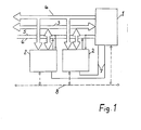
- Fig. 1 shows a schematic representation of the hardware arrangement in a telecontrol station.
- the station contains a central unit 1 and several peripheral devices 2 as participants in a bus system which contains a data bus 3 and a call-command bus 4.
- control lines 5, 6 and stub lines 7 are provided which connect the central unit 1 to the peripheral devices 2.
- a bit-serial bus 8 which is entered with a broken line and which connects all the devices 1, 2 to one another.
- the call command bus 4 which is provided instead of an address bus and whose function is explained in more detail below, all are other components of the telecontrol station known.
- Data is exchanged in the usual way between the subscribers 1, 2 via the 8-bit parallel, byte-serial data bus 3, for example.
- the data bus 3 can supplement the function of the 6-bit parallel call command bus 4, for example.
- control signals for carrying out a known handshake method for a synchronized data exchange are transmitted.
- the stub lines 7 are used for addressing the peripheral devices 2.
- the bit serial bus 8 is provided as a redundant bus.
- the central unit 1 contains a so-called bus manager for controlling the flow of information on all lines 3 to 8.
- the call-command bus 4 and the method according to the invention for data transmission between the subscribers 1, 2 on the transmission system 3 to 7, 8 are explained in more detail below and on the basis of the representation of functions in FIG. 2.
- the invention proposes to define a higher system command language, the elements of which are instructions called call command codes 9, which are transmitted on the call command bus 4 from the central unit 1 to the peripheral devices 2.
- call command codes 9 certain determinations are made, for example with regard to the transmission protocol, bus procedure 10 and security methods, which are to apply to a specific data transmission process.
- a call processing code 9 can be assigned a specific processing function in peripheral devices 2, which are triggered by the reception of the call command code 9.
- the central unit 1 selects a call command code 9 for initiating and carrying out data transmission or for triggering a specific reception-side activity, to which a specific procedure 10 for data exchange on the data bus 3 is assigned.
- the central unit 1 outputs the selected call command code 9 to the call command bus 4 and leaves the information coded with it pending on the call command bus 4 until the transmission process - which is being processed on the data bus 3 - is completed.
- at least one peripheral unit 2 is addressed via at least one of the spur lines 7.
- Several or all peripheral units 2 can also be addressed simultaneously. This results in a so-called device addressing, with which the selected periphery 2 is addressed as a whole, not a specific memory location within the peripheral unit 2.
- call command bus 4 If, for example, six lines are available for the call command bus 4, a maximum of 64 different call command codes 9 can be transmitted. Since a multitude of stipulations are made with a call command code 9, 64 call command codes 9, however, mean a significantly higher system capability and system flexibility than 64 simple memory location addresses.
- a suitable call command code 9 is selected according to the type and meaning of the data to be transmitted or the order to be transmitted.
- 9 different transmission protocols can be defined with call command codes. That is, e.g. be defined that data with variable or fixed block length are transmitted or as individual characters or variable data formats or data structures can be provided.
- the orders mentioned can e.g. Tax orders, such as Resetting or re-storing count values, test routines or switching off the peripheral unit 2.
- Other types of jobs are read jobs, e.g. "Send data input x", “send spontaneous data” or “send standard status” as well as write jobs such as "Write parameter type y" or "Write data output x".
- job command codes e.g. can be carried out with or without a check byte, with or without repetition and certain diagnostic routines can be selected.
- Peripheral units 2 connected to the bus system as participants can be of different types. For example, the further use of peripheral devices 2 from an older system is possible in the new system, such devices interpreting the call-command bus 4 as an address bus. Some call command codes 9 are reserved for these devices in order to display addresses. In addition, a specific handshake procedure can also be specified with a call command code 9 be placed, which can be taken into account, for example, particularly slow peripheral units 2 These measures make the bus system backwards compatible.
- peripheral units 2 which are specially designed for participation in the bus system according to the invention, by no means all devices need to understand all the call command codes 9.
- the peripheral units 2 are only equipped with the necessary skills in accordance with their task.
- the procedure 10 for the transmission of orders or data can also be selected depending on the meaning of the respective orders or data, specifically for a specific transmission process. Memory locations are addressed internally in the peripheral device and are - as a rule - not transmitted (logical addressing).
- the applicability of the invention is not limited to a bus arrangement according to FIG. 1, in which a bit-parallel call command bus 4 for transmitting the call command codes 9 and a bit-parallel data bus 3 are provided.
- the call command codes 9 and the procedures 10 defined therewith can also be used in a bit-serial bus system.
- the peripheral unit 2 is addressed with specially marked address characters in the transmitted bit sequence (telegram). However, the transmission process then takes place much slower, provided the clock rate is the same, and it is necessary to store the received call command code 9 in the peripheral unit 2. From this possibility e.g. Be used if a redundant bus system is to be provided, which is shown in Fig. 1 and 2 as a bit-serial bus system 8.
Abstract
Description
Die Erfindung bezieht sich auf ein Verfahren und eine Anordnung zur Übertragung von Informationen zwischen Teilnehmern an einem Bussystem. Solche Verfahren und Anordnungen werden z.B. angewendet für die Datenübertragung zwischen Geräteeinheiten (Teilnehmern), die an ein Bussystem innerhalb einer Fernwirkstation oder einer sonstigen leittechnischen Station, also einen Stationsbus angeschlossen sind.The invention relates to a method and an arrangement for the transmission of information between participants in a bus system. Such methods and arrangements are e.g. used for data transmission between device units (participants) that are connected to a bus system within a telecontrol station or another control station, that is, a station bus.
Ein solcher Stationsbus ist z.B. in dem Aufsatz "Der Aufbau von Mikrocomputern und ihr Einsatz zur Sicherung von Fernwirktelegrammen", H. Herkert, NTG-Fachberichte Band 66, Seite 47 bis 55, Bild 1 dargestellt. Das dargestellte Bussystem ist mit prinzipiell gleichem Aufbau sowohl als internes Bussystem in einem Mikrocomputer als auch als Stationsbus in einer Fernwirkstation bekannt. Fernwirkstationen können mehrere Geräteeinheiten, die einen Mikroprozessor oder einen Computer enthalten, als Busteilnehmer aufweisen. Ein solches Bussystem enthält als Teilsysteme einen Datenbus, einen Steuerbus und einen Adressenbus. Jedes dieser Teilsysteme weist mehrere parallele Leitungen auf. Außerdem können für unterschiedliche Zwecke zusätzliche Leitungen zwischen einer Zentraleinheit und den übrigen Busteilnehmern vorgesehen sein, z.B. als Interrupt-Leitung, zur Geräte-Adressierung oder zur Synchronisierung.Such a station bus is described, for example, in the essay "The Structure of Microcomputers and Their Use for Securing Telecontrol Telegrams", H. Herkert, NTG Technical Reports Volume 66, pages 47 to 55, Figure 1. The bus system shown is known in principle with the same structure both as an internal bus system in a microcomputer and as a station bus in a telecontrol station. Telecontrol stations can have several device units, which contain a microprocessor or a computer, as bus participants. Such a bus system contains as subsystems a data bus, a control bus and an address bus. Each of these subsystems has several parallel lines. In addition, additional lines can be provided between a central unit and the other bus subscribers for different purposes, for example as an interrupt line, for device addressing or for synchronization.
Eine Datenübertragung - z.B. von einem Prozessor zu einem Ausgabebaustein - wird vorbereitet durch Anlegen einer Adresse am Adressenbus und der Daten am Datenbus. Erst wenn auf dem Steuerbus ein Schreibimpuls gesendet wird, übernimmt die adressierte Speicherstelle das auf dem Datenbus anstehende Bitmuster. Die dabei verwendeten Adressen sind Bezeichnungscode für bestimmte Speicherstellen. Je mehr Speicherstellen die an das Bussystem angeschlossenen Teilnehmer aufweisen, destomehr Adressleitungen - typisch 15 bis 20 Leitungen - sind erforderlich; oder es sind Multiplex-Systeme mit aufwendigen Bussteuerungen notwendig. Für leistungsfähige Systeme müssen sehr hohe Taktraten verwendet werden, wodurch der Hardware-Aufwand und die Störempfindlichkeit hoch sind.A data transfer - e.g. from a processor to an output module - prepared by creating an address on the address bus and the data on the data bus. Only when a write pulse is sent on the control bus does the addressed memory location take over the bit pattern present on the data bus. The addresses used are designation codes for certain storage locations. The more memory locations the subscribers connected to the bus system have, the more address lines - typically 15 to 20 lines - are required; or multiplex systems with complex bus controls are necessary. For high-performance systems, very high clock rates have to be used, which means that the hardware complexity and sensitivity to interference are high.
Der Erfindung liegt die Aufgabe zugrunde, ein Verfahren und eine Anordnung zur Übertragung von Daten zwischen Teilnehmern an einem Bussystem anzugeben, das einen geringen Aufwand für die Steuerung und die Adressierung erfordert und trotzdem leistungsfähig ist.The invention has for its object to provide a method and an arrangement for transmitting data between participants in a bus system, which requires little effort for control and addressing and is still powerful.
Diese Aufgabe wird durch ein Verfahren nach dem Anspruch 1 sowie durch eine Anordnung nach dem Anspruch 9 gelöst. Vorteilhafte Ausgestaltungen sind in Unteransprüchen angegeben.This object is achieved by a method according to
Die mit der Erfindung vorgeschlagene Übertragung von Anweisungen, die Elemente einer höheren System-Kommandosprache sind, hat den Vorteil, daß anstelle eines breiten Adressenbusses (d.h. ein Bus mit vielen Leitungen) ein schmaler Aufruf-Kommando-Bus genügt (d.h. ein Bus mit wenig Leitungen) und je nach Bedeutung der zu übertragenden Daten z.B. unterschiedliche Protokolle, Prozeduren und Sicherungsverfahren vereinbart werden können. An das Bussystem können Geräte unterschiedlicher Fähigkeit angeschlossen werden, d.h. auch Geräte, die nur wenige Codes oder nur einen Code interpretieren können. Weitere Vorteile ergeben sich aus den Unteransprüchen und der nachstehenden Beschreibung eines Ausführungsbeispiels anhand der Zeichnung.The transmission of instructions proposed by the invention, which are elements of a higher system command language, has the advantage that, instead of a wide address bus (ie a bus with many lines), a narrow call command bus is sufficient (ie a bus with few lines) ) and depending on the meaning of the data to be transferred e.g. different protocols, procedures and security procedures can be agreed. Devices of different capabilities can be connected to the bus system, i.e. also devices that can only interpret a few codes or only one code. Further advantages result from the subclaims and the following description of an exemplary embodiment with reference to the drawing.
Es zeigen:
- Fig. 1 die Hardware-Anordnung eines Bussystems in einer Fernwirkstation und
- Fig. 2 eine Darstellung der Funktion des Bussystems.
- Fig. 1 shows the hardware arrangement of a bus system in a telecontrol station and
- Fig. 2 shows the function of the bus system.
Fig. 1 zeigt eine schematisierte Darstellung der Hardware-Anordnung in einer Fernwirkstation. Die Station enthält eine Zentraleinheit 1 und mehrere Peripheriegeräte 2 als Teilnehmer an einem Bussystem, das einen Datenbus 3 und einen Aufruf-Kommando-Bus 4 enthält. Außerdem sind Steuerleitungen 5, 6 sowie Stichleitungen 7 vorgesehen, die die Zentraleinheit 1 mit den Peripheriegeräten 2 verbinden. Zusätzlich kann ein gestrichelt eingetragener bitserieller Bus 8 vorgesehen sein, der alle Geräte 1, 2 miteinander verbindet.Fig. 1 shows a schematic representation of the hardware arrangement in a telecontrol station. The station contains a
Außer dem erfindungsgemäßen Aufruf-Kommando-Bus 4, der anstelle eines Adressenbusses vorgesehen ist, und dessen Funktion weiter unten näher erläutert wird, sind alle übrigen Komponenten der Fernwirkstation bekannt. Über den z.B. 8-Bit-parallelen, byte-seriellen Datenbus 3 werden in üblicher Weise Daten zwischen den Teilnehmern 1, 2 ausgetauscht. Außerdem kann der Datenbus 3 die Funktion des z.B. 6-Bit-parallelen Aufruf-Kommando-Busses 4 ergänzen. Mit Hilfe der Steuerleitungen Master Synch. 5 und Slave Sync. 6 werden Steuersignale zur Durchführung eines bekannten Handshake-Verfahrens für einen synchronisierten Datenaustausch übertragen. Die Stichleitungen 7 werden zur Adressierung der Peripheriegeräte 2 benutzt. Der bitserielle Bus 8 ist als redundanter Bus vorgesehen. Die Zentraleinheit 1 enthält einen sogenannten Bus-Verwalter zur Steuerung des Informationsflusses auf allen Leitungen 3 bis 8.Except for the
Nachstehend und anhand der Darstellung von Funktionen in Fig. 2 wird der Aufruf-Kommando-Bus 4 sowie das erfindungsgemäße Verfahren zur Datenübertragung zwischen den Teilnehmern 1, 2 am Übertragungssystem 3 bis 7, 8 näher erklärt.The call-
Mit der Erfindung wird vorgeschlagen, eine höhere System-Kommandosprache zu definieren, deren Elemente mit Aufruf-Kommando-Codes 9 bezeichnete Anweisungen sind, die auf dem Aufruf-Kommando-Bus 4 von der Zentraleinheit 1 zu den Peripheriegeräten 2 übertragen werden. Mit einem Aufruf-Kommando-Code 9 werden bestimmte Festlegungen, z.B. bezüglich Übertragungsprotokoll, Bus-Prozedur 10 und Sicherungsverfahren getroffen, die für einen bestimmten Datenübertragungsvorgang gelten sollen. Außerdem kann einem Aufruf-Kommando-Code 9 eine bestimmte Verarbeitungsfunktion in Peripheriegeräten 2 zugeordnet sein, die durch den Empfang des Aufruf-Kommando-Codes 9 ausgelöst werden.The invention proposes to define a higher system command language, the elements of which are instructions called
In Fig. 2 ist dargestellt, daß die Zentraleinheit 1 zur Einleitung und Durchführung einer Datenübertragung bzw. zur Auslösung einer bestimmten empfangsseitigen Aktivität einen Aufruf-Kommando-Code 9 auswählt, dem eine bestimmte Prozedur 10 für den Datenaustausch auf dem Datenbus 3 zugeordnet ist. Die Zentraleinheit 1 gibt den gewählten Aufruf-Kommando-Code 9 auf den Aufruf-Kommando-Bus 4 und läßt die damit codierte Information bis zum Abschluß des Übertragungsvorganges - der auf dem Datenbus 3 abgewickelt wird - am Aufruf-Kommando-Bus 4 anstehen. Außerden erfolgt über mindestens eine der Stichleitungen 7 eine Adressierung von mindestens einer Peripherieeinheit 2. Es können auch mehrere oder alle Peripherieeinheiten 2 gleichzeitig adressiert werden. Damit erfolgt eine sogenannte Geräte-Adressierung, womit die ausgewählte Peripherie 2 insgesamt angesprochen wird, nicht eine bestimmte Speicherstelle innerhalb der Peripherieeinheit 2. Mit der Sendung eines Aufruf-Kommando-Codes 9 auf dem Aufruf-Kommando-Bus 4 ist mit dem Empfänger eine Vereinbarung getroffen, bezüglich der mit dem jeweiligen Aufruf-Kommando-Code 9 definierten Festlegungen.2 shows that the
Stehen beispielsweise für den Aufruf-Kommando-Bus 4 sechs Leitungen zur Verfügung, so können maximal 64 unterschiedliche Aufruf-Kommando-Codes 9 übertragen werden. Da mit einem Aufruf-Kommando-Code 9 eine Vielzahl von Festlegungen getroffen werden, bedeuten 64 Aufruf-Kommando-Codes 9 jedoch eine wesentlich höhere System-Fähigkeit und System-Flexibilität als 64 einfache Speicherstellen-Adressen. Die Wahl eines geeigneten Aufruf-Kommando-Codes 9 erfolgt jeweils nach der Art und Bedeutung der zu übertragenden Daten bzw. des zu übertragenden Auftrags.If, for example, six lines are available for the
Wie bereits erwähnt, können mit Aufruf-Kommando-Codes 9 unterschiedliche Übertragungsprotokolle festgelegt werden. Das heißt, es kann z.B. definiert werden, daß Daten mit variabler oder fester Blocklänge übertragen werden oder als Einzelzeichen oder es können variable Datenformate bzw. Datenstrukturen vorgesehen werden.As already mentioned, 9 different transmission protocols can be defined with call command codes. That is, e.g. be defined that data with variable or fixed block length are transmitted or as individual characters or variable data formats or data structures can be provided.
Weiterhin können mit Aufruf-Kommando-Codes 9 Prozeduren unterschiedlichen Typs festgelegt werden. Solche Prozedur-Typen sind z.B.
- a) Auftrag der Zentraleinheit 1 an eine oder
meherere Peripherieeinheiten 2 ohne Datensendung und ohne Antwort derPeripherieeinheit 2. - b) Auftrag der Zentraleinheit 1 an eine
Peripherieeinheit 2 ohne Datensendung; diePeripherieeinheit 2 antwortet mit einer Statusangabe. - c) Auftrag der Zentraleinheit 1 ohne Datensendung, die
Peripherieeinheit 2 sendet Antwortdaten.
- a) Order of the
central unit 1 to one or moreperipheral units 2 without data transmission and without a response from theperipheral unit 2. - b) order of the
central unit 1 to aperipheral unit 2 without data transmission; theperipheral unit 2 replies with a status indication. - c) Order of the
central unit 1 without sending data, theperipheral unit 2 sends response data.
Weitere Varianten sind z.B. Aufträge der Zentraleinheit 1 mit oder ohne Daten, wobei die Peripherieeinheit 2 den empfangenen Auftrag erst an die Zentraleinheit 1 zurücksendet (Auftragsreflexion) und erst dann eine Freigabe zur Durchführung des Auftrags erhält.Other variants are e.g. Orders from the
Eine solche typische Prozedur 10 kann z.B. in folgenden Schritten ablaufen:
- 1. Die
Zentraleinheit 1 sendet auf dem Aufruf-Kommando-Bus 4 einen Aufruf-Kommando-Code 9, der während der gesamten Prozedur weiterhin gesendet wird. Der Aufruf-Kommando-Code 9 braucht daher nicht in denPeripherieeinheiten 2 gespeichert zu werden und kann jederzeit neu gelesen werden. Auf demDatenbus 3 können im ersten Schritt Zusatz-Informationen zum Aufruf-Kommando-Code 9 gesendet werden. - 2. Die
Peripherieeinheit 2 antwortet mit der Sendung von Statusangaben auf demDatenbus 3. - 3.
Die Zentraleinheit 1 sendet Auftragsdaten eventuell in mehreren aufeinanderfolgenden Datenbytes auf dem Datenbus. - 4.
Die Peripherieinheit 2 reflektiert diesen Auftrag durch Rücksendung der empfangenen Daten aufden Datenbus 3. - 5.
Die Zentraleinheit 1 prüft die Übereinstimmung von gesendeten und empfangenen Daten und sendet aufdem Datenbus 3 eine Freigabe zur Durchführung des Auftrages.
- 1. The
central unit 1 sends acall command code 9 on thecall command bus 4, which code continues to be sent during the entire procedure. Thecall command code 9 therefore does not need to be stored in theperipheral units 2 and can be read again at any time. In the first step, additional information on thecall command code 9 can be sent on thedata bus 3. - 2. The
peripheral unit 2 responds by sending status information on thedata bus 3. - 3. The
central unit 1 may send order data in several successive data bytes on the data bus. - 4. The
peripheral unit 2 reflects this order by sending the received data back onto thedata bus 3. - 5. The
central unit 1 checks the correspondence of the data sent and received and sends a release on thedata bus 3 to carry out the order.
Die genannten Aufträge können z.B. Steueraufträge sein, wie z.B. Rücksetzen oder Umspeichern von Zählwerten, Prüf-Routinen oder Abschaltung der Peripherieeinheit 2. Andere Auftragsarten sind Leseaufträge, z.B. "Sende Daten Eingang x", "Sende Spontandaten" oder "Sende Standardstatus" sowie Schreibaufträge wie z.B. "Schreibe Parameter Typ y" oder "Schreibe Daten Ausgang x".The orders mentioned can e.g. Tax orders, such as Resetting or re-storing count values, test routines or switching off the
Schließlich können mit Auftrag-Kommando-Codes 9 unterschiedliche Sicherungsverfahren festgelegt werden, z.B. kann eine Übertragung mit oder ohne Check-Byte, mit oder ohne Wiederholung durchgeführt werden und es können bestimmte Diagnose-Routinen gewählt werden.Finally, 9 different security procedures can be specified with job command codes, e.g. can be carried out with or without a check byte, with or without repetition and certain diagnostic routines can be selected.
An das Bussystem als Teilnehmer angeschlossene Peripherieeinheiten 2 können unterschiedlicher Art sein. Beispielsweise ist die Weiterverwendung von Peripheriegeräten 2 aus einem älteren System in dem neuen System möglich, wobei solche Geräte den Aufruf-Kommando-Bus 4 als Adressenbus interpretieren. Für diese Geräte werden einige Aufruf-Kommando-Codes 9 reserviert zur Darstellung von Adressen. Außerdem kann mit einem Aufruf-Kommando-Code 9 auch ein bestimmtes Handshake-Verfahren festge legt werden, wodurch z.B. auf besonders langsame Peripherieeinheiten 2 Rücksicht genommen werden kann. Durch diese Maßnahmen wird das Bussystem abwärts kompatibel.
Auch von den neuen, speziell für die Teilnahme an dem erfindungsgemäßen Bussystem konzipierten Peripherieeinheiten 2 brauchen keineswegs alle Geräte sämtliche Aufruf-Kommando-Codes 9 zu verstehen. Die Peripherieeinheiten 2 werden lediglich entsprechend ihrer Aufgabe mit den erforderlichen Fähigkeiten ausgestattet. Die Prozedur 10 zur Übertragung von Aufträgen oder Daten kann außerdem je nach Bedeutung der jeweiligen Aufträge oder Daten gewählt werden und zwar individuell für einen bestimmten Übertragungsvorgang. Die Adressierung von Speicherplätzen erfolgt peripheriegeräteintern und wird - in der Regel - nicht übertragen (logische Adressierung).Even the new
Die Anwendbarkeit der Erfindung ist nicht auf eine Busanordnung gemäß der Fig. 1 beschränkt, bei der ein bitparalleler Aufruf-Kommandobus 4 zur Übertragung der Aufruf-Kommando-Codes 9 und ein bitparalleler Datenbus 3 vorgesehen sind. Die Aufruf-Kommando-Codes 9 und die damit festgelegten Prozeduren 10 können auch in einem bitseriellen Bussystem Anwendung finden. Die Adressierung der Peripherieeinheit 2 erfolgt dabei mit speziell gekennzeichneten Adresszeichen in der gesendeten Bitfolge (Telegramm). Allerdings läuft dann der Übertragungsvorgang - gleiche Taktrate vorausgesetzt - wesentlich langsamer ab und es ist eine Speicherung des empfangenen Aufruf-Kommando-Codes 9 in der Peripherieeinheit 2 erforderlich. Von dieser Möglichkeit kann z.B. Gebrauch gemacht werden, wenn ein redundantes Bussystem vorzusehen ist, das in Fig. 1 und 2 als bitserielles Bussystem 8 dargestellt ist.The applicability of the invention is not limited to a bus arrangement according to FIG. 1, in which a bit-parallel
Claims (13)
Priority Applications (1)
| Application Number | Priority Date | Filing Date | Title |
|---|---|---|---|
| AT86117272T ATE104455T1 (en) | 1985-12-14 | 1986-12-11 | METHOD AND ARRANGEMENT FOR THE TRANSMISSION OF INFORMATION BETWEEN PARTICIPANTS IN A BUS SYSTEM. |
Applications Claiming Priority (2)
| Application Number | Priority Date | Filing Date | Title |
|---|---|---|---|
| DE3544378 | 1985-12-14 | ||
| DE19853544378 DE3544378A1 (en) | 1985-12-14 | 1985-12-14 | METHOD AND ARRANGEMENT FOR TRANSMITTING INFORMATION BETWEEN PARTICIPANTS ON A BUS SYSTEM |
Publications (3)
| Publication Number | Publication Date |
|---|---|
| EP0226966A2 true EP0226966A2 (en) | 1987-07-01 |
| EP0226966A3 EP0226966A3 (en) | 1989-11-02 |
| EP0226966B1 EP0226966B1 (en) | 1994-04-13 |
Family
ID=6288520
Family Applications (1)
| Application Number | Title | Priority Date | Filing Date |
|---|---|---|---|
| EP86117272A Expired - Lifetime EP0226966B1 (en) | 1985-12-14 | 1986-12-11 | Method and arrangement for information transmission between users of a bus system |
Country Status (3)
| Country | Link |
|---|---|
| EP (1) | EP0226966B1 (en) |
| AT (1) | ATE104455T1 (en) |
| DE (2) | DE3544378A1 (en) |
Cited By (2)
| Publication number | Priority date | Publication date | Assignee | Title |
|---|---|---|---|---|
| US9689514B2 (en) | 2004-09-28 | 2017-06-27 | Advanced Composite Products & Technology, Inc. | Composite pipe to metal joint |
| US10342958B2 (en) | 2017-06-30 | 2019-07-09 | Abbott Cardiovascular Systems Inc. | System and method for correcting valve regurgitation |
Citations (2)
| Publication number | Priority date | Publication date | Assignee | Title |
|---|---|---|---|---|
| EP0109973A1 (en) * | 1982-12-01 | 1984-06-13 | Johannes Reilhofer | Method and arrangement for the transmission of data among several computers |
| WO1985003147A1 (en) * | 1984-01-13 | 1985-07-18 | Term-Tronics Incorporated | Generic communications terminal |
Family Cites Families (2)
| Publication number | Priority date | Publication date | Assignee | Title |
|---|---|---|---|---|
| US3699525A (en) * | 1970-11-27 | 1972-10-17 | Honeywell Inf Systems | Use of control words to change configuration and operating mode of a data communication system |
| DE2800483B2 (en) * | 1978-01-05 | 1980-02-14 | Siemens Ag, 1000 Berlin Und 8000 Muenchen | Circuit arrangement for controlling microprocessor peripherals |
-
1985
- 1985-12-14 DE DE19853544378 patent/DE3544378A1/en not_active Withdrawn
-
1986
- 1986-12-11 DE DE3689787T patent/DE3689787D1/en not_active Expired - Lifetime
- 1986-12-11 AT AT86117272T patent/ATE104455T1/en not_active IP Right Cessation
- 1986-12-11 EP EP86117272A patent/EP0226966B1/en not_active Expired - Lifetime
Patent Citations (2)
| Publication number | Priority date | Publication date | Assignee | Title |
|---|---|---|---|---|
| EP0109973A1 (en) * | 1982-12-01 | 1984-06-13 | Johannes Reilhofer | Method and arrangement for the transmission of data among several computers |
| WO1985003147A1 (en) * | 1984-01-13 | 1985-07-18 | Term-Tronics Incorporated | Generic communications terminal |
Cited By (6)
| Publication number | Priority date | Publication date | Assignee | Title |
|---|---|---|---|---|
| US9689514B2 (en) | 2004-09-28 | 2017-06-27 | Advanced Composite Products & Technology, Inc. | Composite pipe to metal joint |
| US9810353B2 (en) | 2004-09-28 | 2017-11-07 | Advanced Composite Products & Technology, Inc. | Method of making a composite tube to metal joint |
| US10378684B2 (en) | 2004-09-28 | 2019-08-13 | Advanced Composite Products & Technology, Inc. | Composite tube to metal joint apparatus |
| US11009156B2 (en) | 2004-09-28 | 2021-05-18 | Advanced Composite Products & Technology, Inc. | Composite drill pipe |
| US11143338B2 (en) | 2004-09-28 | 2021-10-12 | Advanced Composite Products & Technology, Inc. | Composite to metal end fitting joint |
| US10342958B2 (en) | 2017-06-30 | 2019-07-09 | Abbott Cardiovascular Systems Inc. | System and method for correcting valve regurgitation |
Also Published As
| Publication number | Publication date |
|---|---|
| EP0226966B1 (en) | 1994-04-13 |
| ATE104455T1 (en) | 1994-04-15 |
| DE3689787D1 (en) | 1994-05-19 |
| DE3544378A1 (en) | 1987-06-19 |
| EP0226966A3 (en) | 1989-11-02 |
Similar Documents
| Publication | Publication Date | Title |
|---|---|---|
| EP0019757B1 (en) | Data processing system in which several preprocessors and a main processor superior to the preprocessors are arranged in a tree-structure | |
| DE2913288C2 (en) | Multiprocessor system with a large number of processor modules | |
| DE2953444C2 (en) | Arrangement and method for a digital data transmission network | |
| DE2350371C3 (en) | Method and device for testing and maintenance of data processing systems by means of spatially distant maintenance stations | |
| CH662025A5 (en) | DIGITAL SWITCHING SYSTEM. | |
| DE3146356A1 (en) | DATA PROCESSING SYSTEM | |
| DE4214303C2 (en) | Communication system | |
| DE3826895C2 (en) | ||
| EP0226966B1 (en) | Method and arrangement for information transmission between users of a bus system | |
| DE2850252C2 (en) | On-screen text system | |
| DE2812009C2 (en) | Messaging system | |
| CH656276A5 (en) | METHOD AND CIRCUIT ARRANGEMENT FOR TRANSMITTING DATA SIGNALS BETWEEN DATA SWITCHING DEVICES OF A DATA SWITCHING SYSTEM. | |
| DE2914665C2 (en) | Telecommunication system, in particular video text system, as well as partially centralized and decentralized circuit module for this system | |
| EP0060932B1 (en) | System with two microcomputers interconnected by a bus coupler | |
| EP0033469A1 (en) | Method and circuit arrangement for transmitting binary signals between peripheral units | |
| DE4321716A1 (en) | Integrated data control and transmission system for controlling multiple peripheral subsystems | |
| EP0231809B1 (en) | Method for integration of one or more supplementary-function modules in telephone exchanges and also access circuit for realisation of the method | |
| EP0306736A2 (en) | Method for the transmission of connection information stored in a telecommunication exchange to an information-processing installation | |
| EP0348810B1 (en) | Method for addressing processor units and circuit arrangement for carrying out the method | |
| EP0477627B1 (en) | Method for connecting communication terminals in services integrating communication networks | |
| DE3136495C2 (en) | ||
| EP0348809B1 (en) | Method for addressing processor units and circuit arrangement for carrying out the method | |
| EP0460403B1 (en) | Method for data transmission in communication exchange | |
| DE3015512C2 (en) | Circuit arrangement for operating a printer in telecommunications, in particular telephone switching systems | |
| DE19542948A1 (en) | Procedure for the cooperation of a telecommunication terminal with an external computer and telecommunication terminal |
Legal Events
| Date | Code | Title | Description |
|---|---|---|---|
| PUAI | Public reference made under article 153(3) epc to a published international application that has entered the european phase |
Free format text: ORIGINAL CODE: 0009012 |
|
| AK | Designated contracting states |
Kind code of ref document: A2 Designated state(s): AT CH DE LI NL SE |
|
| RAP1 | Party data changed (applicant data changed or rights of an application transferred) |
Owner name: ASEA BROWN BOVERI AKTIENGESELLSCHAFT |
|
| PUAL | Search report despatched |
Free format text: ORIGINAL CODE: 0009013 |
|
| AK | Designated contracting states |
Kind code of ref document: A3 Designated state(s): AT CH DE LI NL SE |
|
| 17P | Request for examination filed |
Effective date: 19900330 |
|
| 17Q | First examination report despatched |
Effective date: 19920827 |
|
| GRAA | (expected) grant |
Free format text: ORIGINAL CODE: 0009210 |
|
| AK | Designated contracting states |
Kind code of ref document: B1 Designated state(s): AT CH DE LI NL SE |
|
| REF | Corresponds to: |
Ref document number: 104455 Country of ref document: AT Date of ref document: 19940415 Kind code of ref document: T |
|
| REF | Corresponds to: |
Ref document number: 3689787 Country of ref document: DE Date of ref document: 19940519 |
|
| EAL | Se: european patent in force in sweden |
Ref document number: 86117272.4 |
|
| PLBE | No opposition filed within time limit |
Free format text: ORIGINAL CODE: 0009261 |
|
| STAA | Information on the status of an ep patent application or granted ep patent |
Free format text: STATUS: NO OPPOSITION FILED WITHIN TIME LIMIT |
|
| 26N | No opposition filed | ||
| PGFP | Annual fee paid to national office [announced via postgrant information from national office to epo] |
Ref country code: DE Payment date: 20051212 Year of fee payment: 20 |
|
| PGFP | Annual fee paid to national office [announced via postgrant information from national office to epo] |
Ref country code: SE Payment date: 20051214 Year of fee payment: 20 Ref country code: NL Payment date: 20051214 Year of fee payment: 20 |
|
| PGFP | Annual fee paid to national office [announced via postgrant information from national office to epo] |
Ref country code: CH Payment date: 20051215 Year of fee payment: 20 |
|
| PGFP | Annual fee paid to national office [announced via postgrant information from national office to epo] |
Ref country code: AT Payment date: 20051220 Year of fee payment: 20 |
|
| PG25 | Lapsed in a contracting state [announced via postgrant information from national office to epo] |
Ref country code: NL Free format text: LAPSE BECAUSE OF EXPIRATION OF PROTECTION Effective date: 20061211 |
|
| REG | Reference to a national code |
Ref country code: CH Ref legal event code: PL |
|
| NLV7 | Nl: ceased due to reaching the maximum lifetime of a patent |
Effective date: 20061211 |
|
| EUG | Se: european patent has lapsed |