EP0226845A2 - Single component seal - Google Patents
Single component seal Download PDFInfo
- Publication number
- EP0226845A2 EP0226845A2 EP86116294A EP86116294A EP0226845A2 EP 0226845 A2 EP0226845 A2 EP 0226845A2 EP 86116294 A EP86116294 A EP 86116294A EP 86116294 A EP86116294 A EP 86116294A EP 0226845 A2 EP0226845 A2 EP 0226845A2
- Authority
- EP
- European Patent Office
- Prior art keywords
- end portion
- seal component
- bellows
- axial
- face
- Prior art date
- Legal status (The legal status is an assumption and is not a legal conclusion. Google has not performed a legal analysis and makes no representation as to the accuracy of the status listed.)
- Granted
Links
- 238000007789 sealing Methods 0.000 claims description 81
- 230000000295 complement effect Effects 0.000 claims description 23
- 230000006835 compression Effects 0.000 claims description 21
- 238000007906 compression Methods 0.000 claims description 21
- 230000002787 reinforcement Effects 0.000 claims description 8
- 239000013536 elastomeric material Substances 0.000 claims description 7
- 239000013521 mastic Substances 0.000 claims description 5
- 239000003566 sealing material Substances 0.000 claims description 5
- 230000004323 axial length Effects 0.000 claims 2
- 230000003014 reinforcing effect Effects 0.000 abstract description 11
- 239000012530 fluid Substances 0.000 description 8
- OKTJSMMVPCPJKN-UHFFFAOYSA-N Carbon Chemical compound [C] OKTJSMMVPCPJKN-UHFFFAOYSA-N 0.000 description 4
- 229910052799 carbon Inorganic materials 0.000 description 4
- 238000009434 installation Methods 0.000 description 3
- 238000004519 manufacturing process Methods 0.000 description 3
- -1 steam Substances 0.000 description 3
- 239000002253 acid Substances 0.000 description 2
- 150000007513 acids Chemical class 0.000 description 2
- 239000000463 material Substances 0.000 description 2
- 230000013011 mating Effects 0.000 description 2
- 239000002184 metal Substances 0.000 description 2
- 238000012986 modification Methods 0.000 description 2
- 230000004048 modification Effects 0.000 description 2
- 229920003023 plastic Polymers 0.000 description 2
- 229920001084 poly(chloroprene) Polymers 0.000 description 2
- 230000003068 static effect Effects 0.000 description 2
- 229910000831 Steel Inorganic materials 0.000 description 1
- 238000010276 construction Methods 0.000 description 1
- 239000007789 gas Substances 0.000 description 1
- 239000003507 refrigerant Substances 0.000 description 1
- 239000010959 steel Substances 0.000 description 1
- 230000003746 surface roughness Effects 0.000 description 1
- XLYOFNOQVPJJNP-UHFFFAOYSA-N water Substances O XLYOFNOQVPJJNP-UHFFFAOYSA-N 0.000 description 1
Images


Classifications
-
- F—MECHANICAL ENGINEERING; LIGHTING; HEATING; WEAPONS; BLASTING
- F16—ENGINEERING ELEMENTS AND UNITS; GENERAL MEASURES FOR PRODUCING AND MAINTAINING EFFECTIVE FUNCTIONING OF MACHINES OR INSTALLATIONS; THERMAL INSULATION IN GENERAL
- F16J—PISTONS; CYLINDERS; SEALINGS
- F16J15/00—Sealings
- F16J15/16—Sealings between relatively-moving surfaces
- F16J15/34—Sealings between relatively-moving surfaces with slip-ring pressed against a more or less radial face on one member
- F16J15/36—Sealings between relatively-moving surfaces with slip-ring pressed against a more or less radial face on one member connected by a diaphragm or bellow to the other member
Definitions
- the present invention relates to mechanical rotary seals.
- Compact self-contained cartridge type mechanical seals such as the ones shown in Figs. 1 and 2, are specifically designed for high quantity production of industrial and domestic pumps han- dling water, steam, oil, hydraulic fluids, refrigerants, and gases at pressures as high as 100 psi.
- the seal shown in Fig. 1 is known in the industry as a shaft mounted seal and presses onto the shaft of a pump, while the seal in Fig. 2 is known as a bore mounted seal and presses into the pump housing.
- Such seals use coil springs 10a and 10b, respectively, to maintain an axial force between seal face 12a and complementary surface 14a in Fig. 1, and seal face in complementary surface 14b in Fig. 2.
- Sealing members 16a and 18a are used to seal the face members to the shaft and housing in Fig. 1. Sealing members 16b and 18b are used to seal the facing members to the housing and shaft in Fig. 2. In such arrangements, reinforcing members 20a, 22a and 24a are used to hold sealing member 16a in place in the arrangement shown in Fig. 1. Reinforcing members 20b, 22b and 24b are used to hold the sealing member 16b in place in Fig. 2.
- U.S. Patent No. 3,185,488 discloses a mechanical rotary seal having a sealing member with reinforcing members which does not require the use of a coil spring to maintain the face members in positions against each other.
- the built-in reinforcing members constitute an expensive construction.
- the presence of such reinforcing members makes the seal difficult to install because it binds when it is assembled to the shaft or housing due to its requirement of being slid into position as a single unit so that a tight seal can be maintained.
- such seals have a very short operating range of axial compression which is unforgiving in low tolerance design and operating situations. In addition, the axial force over the operating range varies considerably.
- a seal component for establishing a seal between a rotating shaft and a housing comprising an annular face having front axial portion means for abutting, sealing against, and rotating relative to a complementary surface on one of the housing or the shaft; and an axially extending tubular elastomeric bellows having first end portion means for sealing against the annular face, second end portion means for sealing against the other of the housing or the shaft, and an axially intermediate portion axially extending between the first end portion means and the second end portion means, the axially intermediate portion including means for buckling the bellows around a circumferential area of the bellows, for maintaining the front axial portion of the face in sealing relationship with the complementary surface, and for maintaining the second end portion in the sealing relationship with the shaft upon axial compression of the elastomeric bellows.
- the elastomeric bellows consists of one piece of unreinforced elastomeric material. It also is preferable that the intermediate portion has a slender radial cross section which is less than about one-half of its axial cross section, the intermediate portion diverging from the second end portion to the first end portion at an angle in the range about 10° to about 45°.
- a seal component for establishing a seal between a rotating shaft and a housing comprising an annular face having front axial portion means for abutting, sealing against, and rotating relative to a complementary surface on the housing; and an axially extending tubular elastomeric bellows having first end portion means for sealing against the annular face, second end portion means for sealing against the shaft, and an axially intermediate portion axially extending between the first end portion means and the second end portion means, the axially intermediate portion including means for buckling the bellows around a circumferential area of the bellows, for maintaining the front axial portion of the face in sealing relationship with a complementary surface, and for maintaining the second end portion in sealing relationship with the shaft upon axial compression of the bellows.
- seal component 30 establishes a seal between a rotating shaft 32 and a housing 34.
- Seal component 30 includes an annular face such as carbon face 36 having a front axial portion means such as surface 38 for abutting, sealing against, and rotating relative to a complementary surface on the housing such as housing face 40.
- An axially extending tubular elastomeric bellows 42 in- cludes a first end portion 44 which includes a block of elastomeric material that seals against the rear portion 46 of face 36. Bellows 42 also includes a second end portion 48 for sealing against the shaft 32. Bellows 42 further includes an axially intermediate portion 50 having means for buckling bellows ; 42 around a circumferential area, such as structurally weakened neck area 52, while maintaining the front surface 38 of face 36 in sealing relationship with complementary surface 40 and maintaining second end portion 48 in sealing relationship with shaft 32 upon axial compression of bellows 42. Bellows 42 preferably consists of one piece of elastomeric material composed of ethylene propylene, fluorocarbon, buna, neoprene or similar materials.
- first end portion 44 seals to face 36 without reinforcement and without mastic sealing material.
- second end portion 48 seals to shaft 32 without reinforcement.
- the means for buckling and maintaining includes means for buckling the intermediate portion 50 towards shaft 32 so that second end portion 48 grips shaft 32 with an increasing force as bellows 42 is axially compressed.
- the geometric arrangement of bellows 42 is the means which allows this to occur.
- the means for buckling and maintaining sealing relationship includes neck area 52, having a narrow cross-section, positioned at the junction between the intermediate portion 50 and the first end portion 44.
- Intermediate portion 50 has a slender radial cross section and first and second end portions 44 and 48 have comparatively wide radial cross sections relative to intermediate portion 50.
- the radial cross section of intermediate portion 50 is preferably less than about one-half its axial cross section.
- the intermediate portion 50 generally extends longitudinally in the axial direction neck area 52 is positioned radially outward of the junction between intermediate portion 50 and second end portion 48.
- intermediate portion 50 diverges from second end portion 48 to first end portion 44 at an angle in the range ' of about 10° to 45°.
- Intermediate portion 50 has a radial cross section which increases in width in the direction from the first end portion 44 to the second end portion 48.
- the structurally weakened neck area 52 preferably includes a first V portion 54 on the radially outward side of seal component 30, and a second V portion 56 on the radially inner side of seal component 30.
- the convergence point 58 of the first V portion is radially inward of the convergence point 60 of the second V portion.
- bellows 42 The geometry which provides the buckling allows bellows 42 to provide a substantially constant axial force over the operating range of the axial compression of bellows 42.
- the operating range of bellows 42 is greatly increased from conventional seals which would have an operating range of approximately 0'.040 inches to a substantially greater operating range of about 0.140 inches. This greater operating range and the constant axial force over the operating range allows the inventive seal to be used in low tolerance situations where axial play is involved.
- the seal is shown in a compressed state within the operating range.
- the seal can be further or lesser compressed than in this position and still be within the operating range where sealing occurs and a constant axial force is present.
- the outer surface 62 of intermediate portion 50 and the convergence point 60 of the second V portion are generally aligned on the same conical surface so that a projection of surface 62 would intersect convergence point 60.
- the convergence point 60 of the second V portion 56 and the center 46 of the radial cross section of face 36 are positioned at the same radial distance from the longitudinal axis 68 of seal component 30.
- Receptacle means such as cavity 70 is positioned in the front axial face of the first end portion 44.
- the rear axial portion 46 of the face 36 includes a convexly curved central cross section 72 and a forwardly and outwardly angled radially outer portion 74. This geometric arrangement allows the force of bellows 42 to flow around the portions of face 36 including convexly curved central cross section 72 and forwardly and outwardly, angled radially outer portion 74 to provide a retaining force on the radially outward part of face 36.
- the radially outer portion of cavity 70 includes a detent 76 for providing positive restraint against relative axial movement between face 36 and bellows 42.
- Detent 76 includes lips in bellows 42 which engage a notch in face 36. In such a fashion, the two pieces can be molded separately and assembled together by snapping them in place to unitize the assembly. Radially inner and outer portions 76 and 78 are used for more firmly securing 36 face and elastomeric bellows 42.
- This inventive seal component unlike conventional seal components, consists of only one element other than face 36, namely, bellows 42 which, as an unreinforced single component, performs the duties of many elements on conventional seals which are not required in this arrangement.
- four duties need to be performed by seals. They include providing axial force, rotational drive, a primary seal between relatively rotating mating faces and a secondary seal between static surfaces.
- the bellows of the inventive arrangement provides all of these duties except providing a primary seal.
- Second end portion 48 includes an axial sealing surface 80 for sealing against an axial portion of shaft 32 and an inner radial sealing portion 64 for sealing against the outer radial portion of the shaft. As shown in Fig. 3, this is accomplished by using a shaft 32 with a step formed to result in lesser and greater outer radii and an intermediate axial portion.
- Second end portion 48 includes a second axial surface 82 having an inner radius 84 less than the outer radius 86 of the axial portion of the shaft. Since P 1 is greater than P 0 , this relationship causes the axial portion 80 of second end portion 48 to be sealed against the axial portion of the shaft. That sealing force increases as the fluid pressure P 1 increases thereby forming an even tighter seal under higher pressures.
- the first end portion 44 includes a rear axial surface 88 having a minimum outer radius less than the outer radius of face means 36 so that the pressure P 1 will bias first end portion 44 toward housing face 40 and tend to increase this biasing force as the pressure of the sealed fluid P 1 increases.
- a seal component for establishing a seal between a rotating shaft and a housing comprising an annular face having front axial portion means for abutting, sealing against, and rotating relative to a comple- mentary surface on the shaft; and an axially extending tubular elastomeric bellows having first end portion means for sealing against the annular face, second end portion means for sealing against the housing, and an axially intermediate portion axially extending between the first end portion means and the second end portion means, the axially intermediate portion including means for buckling the bellows around a circumferential area of the bellows, for maintaining the front axial portion of the face in sealing realtionship with a complementary surface, and for main- the second end portion sealing relationship the taining the second end portion in sealing relationship with the housing upon axial compression of the bellows.
- seal component 130 establishes a seal between a rotating shaft 132 and a housing 134.
- Seal component 130 includes an annular face such as carbon face 136 having a front axial portion 138 for abutting, sealing against, and rotating relative to a complementary surface on the shaft such as shaft face 140.
- An axially extending tubular elastomeric bellows 142 includes a first end portion 144 which includes a block of elastomeric material that seals against the rear portion 146 of face 136. Bellows 142 also includes a second end portion 148 for sealing against the housing 134. Bellows 142 further includes an axially intermediate portion 150 having means for buckling bellows 42 around a circumferential area, such as structurally weakened neck area 152, while maintaining the front surface 138 of face 136 in sealing relationship with complementary surface 140 and maintaining second end portion 148 in sealing relationship with shaft 132 upon axial compression of bellows 142. Bellows 142 preferably consists of one piece of elastomeric material composed of ethylene propylene, fluorocarbon, buna, neoprene or similar materials.
- Face 136 and bellows 142 are each molded separately and assembled together with a snapping action to unitize the assembly.
- bellows 142 is unreinforced and does not need to contain any metallic or plastic reinforcing rings in order to assist in locking bellows 142 on rotating shaft 132 or face 136. Therefore, the first end portion seals to face 136 without reinforcement and without mastic sealing material.
- second end portion 148 seals to shaft 132 without reinforcement.
- the means for buckling and maintaining includes means for buckling the intermediate portion 150 toward shaft 132 so that second end portion 148 grips housing 134 with an increasing force as bellows 142 is axially compressed.
- the geometric arrangement of bellows 142 is the means which allows this to occur.
- the means for buckling and maintaining sealing relationship includes neck area 152, having a narrow cross-section, positioned at the junction between intermediate portion 150 and second end portion 148.
- Intermediate portion 150 has a slender radial cross-section and first and second portions 144 and 148 have comparatively wide radial cross-sections relative to intermediate portion 150.
- the radial dross-section of intermediate portion 150 is preferably less than about one half its axial cross-section.
- the intermediate portion 150 also generally extends longitudinally in the axial direction and neck area 152 is positioned radially outward of the junction between intermediate portion 150 and first end portion 144.
- intermediate portion 150 diverges from first end portion 144 to second end portion 148 at an angle in the range of about 10° to 45 0 .
- Intermediate portion 150 has a radial cross-section which increases in width in the direction from second end portion 148 to first end portion 144.
- the structurally weakened neck area 152 preferably includes a first V portion 15 4 on the radially outward side of seal component 130, and a second V portion 156 on the radially inner side of seal component 130.
- the convergence point 158 of the first V portion is radially inward of the second convergence point 160 of the second V portion.
- bellows 142 The geometry which provides the buckling allows bellows 142 to provide a substantially constant axial force over the operating range of the axial compression of bellows 142.
- the operating range of bellows 142 is greatly increased from conventional seals which would have an operating range of approximately 0.040 inches to substantially greater operating range of about 0.140 inches. This greater operating range and the constant axial force over the operating range allows the inventive seal to be used in low tolerance situations where axial play is involved.
- the seal is shown in a compressed state within the operating range.
- the seal can be further or lesser compressed than in this position and still be within the operating range where sealing occurs and a constant axial force is present.
- a force is maintained between faces 138 and 140 which is sufficiently high in order to provide a good seal and sufficiently low so as not to generate excessive heat due to friction.
- the absence of reinforcement rings and the buckling arrangement allow the outside diameter 164 of second end portion 146 to be sufficiently small relative to the inside diameter 166 of housing 134 so as not to bind when seal component 130 is assembled to housing 134. This is so even though the outside diameter of the second end portion preferably is larger than the inside diameter of the housing.
- Such ease in assembly is important and would not be possible with conventional seals using reinforcing rings because they would need to have as tight a fit during installation as during operation, a condition which is unnecessary due to the geometric arrangement of bellows 142 of the present invention.
- the outer surface 162 of intermediate portion 150 and the convergence point 160 of second V portion are generally aligned on the same conical surface so that a projection of surface 162 would intersect convergence point 160.
- the convergence point 160 of the second V portion 156 and the center 146 of the radial cross-section of face 136 are positioned at the same radial distance from the longitudinal axis 168 of seal component 130.
- R ecepticle means such as cavity 170 is positioned in the front axial face of first end portion 144.
- the rear axial portion 146 of face 136 includes a convexly curved central cross-section 172 and a forwardly and outwardly angled radially outer portion 174.
- This geometric arrangement allows the force of bellows 142 to flow around the portions of face 136 including convexly curved central cross-section 172 and forwardly and outwardly angled radially outer portion 174 to provide a retaining force on the radially outward part of face 136.
- the radially outward portion of cavity 170 includes a detent 176 for providing positive restraint against relative axial movement between face 136 and bellows 142.
- Detent 176 includes lips in bellows 142 which engage a notch in ' face 136. In such a fashion, the two pieces can be molded separately and assembled together by snapping them in place to unitize the assembly.
- This inventive seal component unlike conventional seal components, consists of only one element other than face 136, namely, bellows 42 which, as an unreinforced single component, performs the duties of many elements on conventional seals which are not required in this arrangement.
- four duties need to be performed by seals. They include providing axial force, rotational drive, a primary seal between relatively rotating mating faces and a secondary seal between static surfaces.
- the bellows of the inventive arrangement provides all of these duties except providing a primary seal.
- Second end portion 148 includes an axial sealing surface 180 for sealing against an axial portion of the housing 134 and an outer radial sealing portion 164 for sealing against the inner radial portion of housing 134. As shown in Fig. 4, this is accomplished by using a housing 134 with a step to form axial and radial surfaces.
- the outer radial surface of facing 136 has an outer radius greater than the minimum radius of bellows 142 so that P l will bias first end portion 144 toward seal face 140 and tend to increase this biasing force as the pressure of the sealed fluid P l increases.
- each size mold for a bellows can serve both as a shaft mounted or bore mounted seal with minor modifications in the mold.
- the following table illustrates that a bellows produced by a particular mold would serve as a seal for a different size shaft if used in a shaft mounted seal arrangement than the size shaft used in a bore mounted arrangement.
- the inventive arrangement has a wider range of tolerance than conventional arrangements because it is easy to install, it accommodates different surface roughnesses of a shaft or housing, and it is able to accommodate shafts and housings which are made in both English and metric units from one set of molds.
- the following table illustrates how each mold in a series of molds can produce a seal which is usable both on a shaft calibrated in the English system and a slightly different size shaft calibrated in the metric system.
Landscapes
- Engineering & Computer Science (AREA)
- General Engineering & Computer Science (AREA)
- Mechanical Engineering (AREA)
- Mechanical Sealing (AREA)
- Sealing Devices (AREA)
Abstract
Description
- The present invention relates to mechanical rotary seals.
- Compact self-contained cartridge type mechanical seals, such as the ones shown in Figs. 1 and 2, are specifically designed for high quantity production of industrial and domestic pumps han- dling water, steam, oil, hydraulic fluids, refrigerants, and gases at pressures as high as 100 psi. The seal shown in Fig. 1 is known in the industry as a shaft mounted seal and presses onto the shaft of a pump, while the seal in Fig. 2 is known as a bore mounted seal and presses into the pump housing. Such seals use
coil springs seal face 12a andcomplementary surface 14a in Fig. 1, and seal face incomplementary surface 14b in Fig. 2. Sealingmembers Sealing members members member 16a in place in the arrangement shown in Fig. 1. Reinforcingmembers member 16b in place in Fig. 2. - There are many drawbacks to these coil spring seal designs. The large number of component parts makes manufacture complicated. The use of a steel spring coil produces an uneven load distribution on the periphery of the carbon face member. The seal is unsuitable for acids and highly corrosive fluids because it contains metallic parts. The seal in Fig. 2 has metal-to-metal interference with the pump housing which, when installed, requires the use of an "0" ring or a very tight fit using a mastic sealing material applied during the installation.
- U.S. Patent No. 3,185,488 discloses a mechanical rotary seal having a sealing member with reinforcing members which does not require the use of a coil spring to maintain the face members in positions against each other. Although several of the drawbacks of the coil spring biassed seal are overcome by this arrangement, other drawbacks remain and new problems are created. In particular, the built-in reinforcing members constitute an expensive construction. Also, the presence of such reinforcing members makes the seal difficult to install because it binds when it is assembled to the shaft or housing due to its requirement of being slid into position as a single unit so that a tight seal can be maintained. Furthermore, such seals have a very short operating range of axial compression which is unforgiving in low tolerance design and operating situations. In addition, the axial force over the operating range varies considerably.
- Accordingly, it is an object of the present invention to provide a seal which does not have a large number of component parts which makes manufacture complicated.
- It is another object of the present invention to provide a biassed member which provides an even load distribution on the periphery of the carbon face.
- It is a further object of the present invention to provide a seal having no metallic parts, thereby making the seal suitable for use with acids and highly corrosive fluids.
- It is also an object of the present invention to provide a seal having no metal-to-metal interference with the pump housing and no need for the use of an "0" ring or mastic sealing material.
- It is an additional object of the present invention to provide a seal which requires no reinforcing members to hold the sealing members in place.
- It is another object of the present invention to provide a seal which can be easily assembled and installed on the shaft and housing without binding the shaft and housing during assembly.
- It is a further object of the present invention to provide a seal having a long operating range of axial compression.
- It is also an object of the present invention to provide a seal having a substantially constant axial force over the operating range of axial compression.
- Additional objects and advantages of the invention will be set forth in the description which follows, and in part will be obvious from the description, or may be learned by practice of the invention. The objects and advantages of the invention may be realized and obtained by means of the instrumentalities and combinations particularly pointed out in the appended claims.
- To achieve the foregoing objects, and in accordance with the purposes of the invention as embodied and broadly described herein, there is provided a seal component for establishing a seal between a rotating shaft and a housing comprising an annular face having front axial portion means for abutting, sealing against, and rotating relative to a complementary surface on one of the housing or the shaft; and an axially extending tubular elastomeric bellows having first end portion means for sealing against the annular face, second end portion means for sealing against the other of the housing or the shaft, and an axially intermediate portion axially extending between the first end portion means and the second end portion means, the axially intermediate portion including means for buckling the bellows around a circumferential area of the bellows, for maintaining the front axial portion of the face in sealing relationship with the complementary surface, and for maintaining the second end portion in the sealing relationship with the shaft upon axial compression of the elastomeric bellows.
- It is preferable that the elastomeric bellows consists of one piece of unreinforced elastomeric material. It also is preferable that the intermediate portion has a slender radial cross section which is less than about one-half of its axial cross section, the intermediate portion diverging from the second end portion to the first end portion at an angle in the range about 10° to about 45°.
- The accompanying drawings, which are incorporated in and constitute a part of the specification, illustrate a preferred embodiment of the invention and, together with the general description given above, and the detailed description of the preferred embodiment given below, serve to explain the principles of the invention.
-
- Fig. 1 is a cross section view of a conventional shaft mounted seal;
- Fig. 2 is a cross section view of a conventional bore mounted seal;
- Fig. 3 is a cross section view of a shaft mounted seal in an uncompressed state incorporating the teachings of the present invention; and
- Fig. 4 is a cross section view of a bore mounted seal in an uncompressed state incorporating the teachings of the present invention.
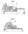
- Fig. 5 is a cross section view of the shaft mounted seal shown in Fig. 3 in a compressed state within the operating range.
- Fig. 6 is a cross section view of the bore mounted seal shown in Fig. 4 in a compressed state within the operating range.
- Reference will now be made in detail to the present preferred embodiment of the invention as illustrated in the accompanying drawings.
- In accordance with the present invention as used in a shaft mounted seal embodiment, there is provided a seal component for establishing a seal between a rotating shaft and a housing comprising an annular face having front axial portion means for abutting, sealing against, and rotating relative to a complementary surface on the housing; and an axially extending tubular elastomeric bellows having first end portion means for sealing against the annular face, second end portion means for sealing against the shaft, and an axially intermediate portion axially extending between the first end portion means and the second end portion means, the axially intermediate portion including means for buckling the bellows around a circumferential area of the bellows, for maintaining the front axial portion of the face in sealing relationship with a complementary surface, and for maintaining the second end portion in sealing relationship with the shaft upon axial compression of the bellows.
- As shown in the shaft mounted seal embodiment of Fig. 3,
seal component 30 establishes a seal between a rotatingshaft 32 and ahousing 34.Seal component 30 includes an annular face such ascarbon face 36 having a front axial portion means such as surface 38 for abutting, sealing against, and rotating relative to a complementary surface on the housing such ashousing face 40. - An axially extending tubular
elastomeric bellows 42, in- cludes a first end portion 44 which includes a block of elastomeric material that seals against therear portion 46 offace 36. Bellows 42 also includes a second end portion 48 for sealing against theshaft 32.Bellows 42 further includes an axiallyintermediate portion 50 having means for buckling bellows ; 42 around a circumferential area, such as structurally weakenedneck area 52, while maintaining the front surface 38 offace 36 in sealing relationship withcomplementary surface 40 and maintainingsecond end portion 48 in sealing relationship withshaft 32 upon axial compression ofbellows 42.Bellows 42 preferably consists of one piece of elastomeric material composed of ethylene propylene, fluorocarbon, buna, neoprene or similar materials. -
Face 36 andbellows 42 are each molded separately and assem- bled together with a snapping action to unitize the assembly. According to the present invention,bellows 42 is unreinforced and does not need to contain any metallic or plastic reinforcing rings in order to assist in lockingbellows 42 on rotatingshaft 32 orface 36. Therefore,first end portion 44 seals to face 36 without reinforcement and without mastic sealing material. In addition,second end portion 48 seals toshaft 32 without reinforcement. - According to the present invention, the means for buckling and maintaining includes means for buckling the
intermediate portion 50 towardsshaft 32 so thatsecond end portion 48grips shaft 32 with an increasing force asbellows 42 is axially compressed. The geometric arrangement ofbellows 42 is the means which allows this to occur. - In particular, according to the present invention, the means for buckling and maintaining sealing relationship includes
neck area 52, having a narrow cross-section, positioned at the junction between theintermediate portion 50 and thefirst end portion 44.'Intermediate portion 50 has a slender radial cross section and first andsecond end portions intermediate portion 50. The radial cross section ofintermediate portion 50 is preferably less than about one-half its axial cross section. Theintermediate portion 50 generally extends longitudinally in the axialdirection neck area 52 is positioned radially outward of the junction betweenintermediate portion 50 andsecond end portion 48. Also,intermediate portion 50 diverges fromsecond end portion 48 tofirst end portion 44 at an angle in the range ' of about 10° to 45°.Intermediate portion 50 has a radial cross section which increases in width in the direction from thefirst end portion 44 to thesecond end portion 48. - According to the present invention, the structurally weakened
neck area 52 preferably includes afirst V portion 54 on the radially outward side ofseal component 30, and asecond V portion 56 on the radially inner side ofseal component 30. Theconvergence point 58 of the first V portion is radially inward of theconvergence point 60 of the second V portion. - The geometry which provides the buckling allows
bellows 42 to provide a substantially constant axial force over the operating range of the axial compression ofbellows 42. In addition, the operating range ofbellows 42 is greatly increased from conventional seals which would have an operating range of approximately 0'.040 inches to a substantially greater operating range of about 0.140 inches. This greater operating range and the constant axial force over the operating range allows the inventive seal to be used in low tolerance situations where axial play is involved. - As shown in Fig. 5, the seal is shown in a compressed state within the operating range. The seal can be further or lesser compressed than in this position and still be within the operating range where sealing occurs and a constant axial force is present.
- A force is maintained between
faces 38 and 40 which is sufficiently high in order to provide a good seal and sufficiently low so as not to generate excessive heat due to friction. In addition, the absence of reinforcement rings and the buckling arrangement allow theinside diameter 64 ofsecond end portion 48 to be sufficiently large relative to theoutside diameter 66 ofshaft 32 so as not to bind whenseal component 30 is assembled toshaft 32. This is so even though the inside diameter of the second end portion preferably is smaller than the outside diameter of the shaft. Such ease in assembly is important and would not be possible with conventional seals using reinforcing rings because they would need to have as tight a fit during installation as during operation, a condition which is unnecessary due to the geometric arrangement ofbellows 42 of the present invention. : - Other geometric characteristics of the present invention aid in establishing these properties and also establish properties which allow bellows 42 to be secured to face 36 while preventing undesirable torque on
face 36 due to axial compression ofbellows 42 during use. Theouter surface 62 ofintermediate portion 50 and theconvergence point 60 of the second V portion are generally aligned on the same conical surface so that a projection ofsurface 62 would intersectconvergence point 60. In addition, theconvergence point 60 of thesecond V portion 56 and thecenter 46 of the radial cross section offace 36 are positioned at the same radial distance from thelongitudinal axis 68 ofseal component 30. - Receptacle means such as
cavity 70 is positioned in the front axial face of thefirst end portion 44. The rearaxial portion 46 of theface 36 includes a convexly curvedcentral cross section 72 and a forwardly and outwardly angled radiallyouter portion 74. This geometric arrangement allows the force ofbellows 42 to flow around the portions offace 36 including convexly curvedcentral cross section 72 and forwardly and outwardly, angled radiallyouter portion 74 to provide a retaining force on the radially outward part offace 36. - It is preferable that the radially outer portion of
cavity 70 includes adetent 76 for providing positive restraint against relative axial movement betweenface 36 and bellows 42.Detent 76 includes lips inbellows 42 which engage a notch inface 36. In such a fashion, the two pieces can be molded separately and assembled together by snapping them in place to unitize the assembly. Radially inner andouter portions - This inventive seal component, unlike conventional seal components, consists of only one element other than
face 36, namely, bellows 42 which, as an unreinforced single component, performs the duties of many elements on conventional seals which are not required in this arrangement. In particular, four duties need to be performed by seals. They include providing axial force, rotational drive, a primary seal between relatively rotating mating faces and a secondary seal between static surfaces. The bellows of the inventive arrangement provides all of these duties except providing a primary seal. - When this seal is used, atmospheric pressure Po exists on ; the radially inner portion of the seal and a higher pressure P1 exists on the radially outer portion of the seal due to the pressure of the sealed fluid.
Second end portion 48 includes anaxial sealing surface 80 for sealing against an axial portion ofshaft 32 and an innerradial sealing portion 64 for sealing against the outer radial portion of the shaft. As shown in Fig. 3, this is accomplished by using ashaft 32 with a step formed to result in lesser and greater outer radii and an intermediate axial portion. -
Second end portion 48 includes a secondaxial surface 82 having aninner radius 84 less than theouter radius 86 of the axial portion of the shaft. Since P1 is greater than P0, this relationship causes theaxial portion 80 ofsecond end portion 48 to be sealed against the axial portion of the shaft. That sealing force increases as the fluid pressure P1 increases thereby forming an even tighter seal under higher pressures. Similarly, thefirst end portion 44 includes a rearaxial surface 88 having a minimum outer radius less than the outer radius of face means 36 so that the pressure P1 will biasfirst end portion 44 towardhousing face 40 and tend to increase this biasing force as the pressure of the sealed fluid P1 increases. - In accordance with the present invention as used in a bore mounted seal embodiment, there is provided a seal component for establishing a seal between a rotating shaft and a housing comprising an annular face having front axial portion means for abutting, sealing against, and rotating relative to a comple- mentary surface on the shaft; and an axially extending tubular elastomeric bellows having first end portion means for sealing against the annular face, second end portion means for sealing against the housing, and an axially intermediate portion axially extending between the first end portion means and the second end portion means, the axially intermediate portion including means for buckling the bellows around a circumferential area of the bellows, for maintaining the front axial portion of the face in sealing realtionship with a complementary surface, and for main- the second end portion sealing relationship the taining the second end portion in sealing relationship with the housing upon axial compression of the bellows.
- As shown in the bore mounted seal embodiment of Fig. 4,
seal component 130 establishes a seal between arotating shaft 132 and ahousing 134.Seal component 130 includes an annular face such ascarbon face 136 having a frontaxial portion 138 for abutting, sealing against, and rotating relative to a complementary surface on the shaft such asshaft face 140. - An axially extending tubular elastomeric bellows 142, includes a
first end portion 144 which includes a block of elastomeric material that seals against therear portion 146 offace 136.Bellows 142 also includes asecond end portion 148 for sealing against thehousing 134.Bellows 142 further includes an axiallyintermediate portion 150 having means for bucklingbellows 42 around a circumferential area, such as structurally weakenedneck area 152, while maintaining thefront surface 138 offace 136 in sealing relationship withcomplementary surface 140 and maintainingsecond end portion 148 in sealing relationship withshaft 132 upon axial compression ofbellows 142.Bellows 142 preferably consists of one piece of elastomeric material composed of ethylene propylene, fluorocarbon, buna, neoprene or similar materials. - Face 136 and bellows 142 are each molded separately and assembled together with a snapping action to unitize the assembly. According to the present invention, bellows 142 is unreinforced and does not need to contain any metallic or plastic reinforcing rings in order to assist in locking bellows 142 on
rotating shaft 132 orface 136. Therefore, the first end portion seals to face 136 without reinforcement and without mastic sealing material. In addition,second end portion 148 seals toshaft 132 without reinforcement. - According to the present invention, the means for buckling and maintaining includes means for buckling the
intermediate portion 150 towardshaft 132 so thatsecond end portion 148 grips housing 134 with an increasing force asbellows 142 is axially compressed. The geometric arrangement ofbellows 142 is the means which allows this to occur. - In particular, according to the present invention, the means for buckling and maintaining sealing relationship includes
neck area 152, having a narrow cross-section, positioned at the junction betweenintermediate portion 150 andsecond end portion 148.Intermediate portion 150 has a slender radial cross-section and first andsecond portions intermediate portion 150. The radial dross-section ofintermediate portion 150 is preferably less than about one half its axial cross-section. Theintermediate portion 150 also generally extends longitudinally in the axial direction andneck area 152 is positioned radially outward of the junction betweenintermediate portion 150 andfirst end portion 144. Also,intermediate portion 150 diverges fromfirst end portion 144 tosecond end portion 148 at an angle in the range of about 10° to 450.Intermediate portion 150 has a radial cross-section which increases in width in the direction fromsecond end portion 148 tofirst end portion 144. - According to the present invention, the structurally weakened
neck area 152 preferably includes a first V portion 154 on the radially outward side ofseal component 130, and asecond V portion 156 on the radially inner side ofseal component 130. Theconvergence point 158 of the first V portion is radially inward of thesecond convergence point 160 of the second V portion. - The geometry which provides the buckling allows
bellows 142 to provide a substantially constant axial force over the operating range of the axial compression ofbellows 142. In addition, the operating range ofbellows 142 is greatly increased from conventional seals which would have an operating range of approximately 0.040 inches to substantially greater operating range of about 0.140 inches. This greater operating range and the constant axial force over the operating range allows the inventive seal to be used in low tolerance situations where axial play is involved. - As shown in Fig. 6, the seal is shown in a compressed state within the operating range. The seal can be further or lesser compressed than in this position and still be within the operating range where sealing occurs and a constant axial force is present.
- A force is maintained between
faces outside diameter 164 ofsecond end portion 146 to be sufficiently small relative to theinside diameter 166 ofhousing 134 so as not to bind whenseal component 130 is assembled tohousing 134. This is so even though the outside diameter of the second end portion preferably is larger than the inside diameter of the housing. Such ease in assembly is important and would not be possible with conventional seals using reinforcing rings because they would need to have as tight a fit during installation as during operation, a condition which is unnecessary due to the geometric arrangement ofbellows 142 of the present invention. - Other geometric characteristics of the present invention aid in establishing these properties and also establish properties which allow bellows 142 to be secured to face 136 while preventing undesirable torque on
face 136 due to axial compression ofbellows 142 during use. Theouter surface 162 ofintermediate portion 150 and theconvergence point 160 of second V portion are generally aligned on the same conical surface so that a projection ofsurface 162 would intersectconvergence point 160. In addition, theconvergence point 160 of thesecond V portion 156 and thecenter 146 of the radial cross-section offace 136 are positioned at the same radial distance from thelongitudinal axis 168 ofseal component 130. - Recepticle means such as
cavity 170 is positioned in the front axial face offirst end portion 144. The rearaxial portion 146 offace 136 includes a convexly curvedcentral cross-section 172 and a forwardly and outwardly angled radiallyouter portion 174. This geometric arrangement allows the force ofbellows 142 to flow around the portions offace 136 including convexly curvedcentral cross-section 172 and forwardly and outwardly angled radiallyouter portion 174 to provide a retaining force on the radially outward part offace 136. - It is preferable that the radially outward portion of
cavity 170 includes adetent 176 for providing positive restraint against relative axial movement betweenface 136 and bellows 142.Detent 176 includes lips inbellows 142 which engage a notch in 'face 136. In such a fashion, the two pieces can be molded separately and assembled together by snapping them in place to unitize the assembly. - This inventive seal component, unlike conventional seal components, consists of only one element other than
face 136, namely, bellows 42 which, as an unreinforced single component, performs the duties of many elements on conventional seals which are not required in this arrangement. In particular, four duties need to be performed by seals. They include providing axial force, rotational drive, a primary seal between relatively rotating mating faces and a secondary seal between static surfaces. The bellows of the inventive arrangement provides all of these duties except providing a primary seal. - When this seal is used, atmospheric pressure Po exists on the radially inner portion on the seal and a higher pressure P1 exists on the radially outer portion of the seal due to the pressure of the sealed fluid.
Second end portion 148 includes anaxial sealing surface 180 for sealing against an axial portion of thehousing 134 and an outerradial sealing portion 164 for sealing against the inner radial portion ofhousing 134. As shown in Fig. 4, this is accomplished by using ahousing 134 with a step to form axial and radial surfaces. - The outer radial surface of facing 136 has an outer radius greater than the minimum radius of
bellows 142 so that Pl will biasfirst end portion 144 towardseal face 140 and tend to increase this biasing force as the pressure of the sealed fluid Pl increases. - An additional feature of the inventive arrangement is that each size mold for a bellows can serve both as a shaft mounted or bore mounted seal with minor modifications in the mold. The following table illustrates that a bellows produced by a particular mold would serve as a seal for a different size shaft if used in a shaft mounted seal arrangement than the size shaft used in a bore mounted arrangement.

- Also, it can be seen that the inventive arrangement has a wider range of tolerance than conventional arrangements because it is easy to install, it accommodates different surface roughnesses of a shaft or housing, and it is able to accommodate shafts and housings which are made in both English and metric units from one set of molds. For instance, the following table illustrates how each mold in a series of molds can produce a seal which is usable both on a shaft calibrated in the English system and a slightly different size shaft calibrated in the metric system.

- Additional advantages and modifications will readily occur to those skilled in the art. The invention in its broader aspects is, therefore, not limited to the specific details, representative apparatus and illustrative examples shown and de- scribed. Accordingly, departures may be made from such details without departing from the spirit or scope of applicants' general inventive concept.
Claims (55)
Applications Claiming Priority (2)
| Application Number | Priority Date | Filing Date | Title |
|---|---|---|---|
| US81123185A | 1985-12-20 | 1985-12-20 | |
| US811231 | 1985-12-20 |
Publications (3)
| Publication Number | Publication Date |
|---|---|
| EP0226845A2 true EP0226845A2 (en) | 1987-07-01 |
| EP0226845A3 EP0226845A3 (en) | 1988-07-20 |
| EP0226845B1 EP0226845B1 (en) | 1992-09-02 |
Family
ID=25205956
Family Applications (1)
| Application Number | Title | Priority Date | Filing Date |
|---|---|---|---|
| EP86116294A Expired EP0226845B1 (en) | 1985-12-20 | 1986-11-24 | Single component seal |
Country Status (6)
| Country | Link |
|---|---|
| US (1) | US5013051A (en) |
| EP (1) | EP0226845B1 (en) |
| JP (1) | JPH0726690B2 (en) |
| CA (1) | CA1331389C (en) |
| DE (1) | DE3686639T2 (en) |
| NO (1) | NO865126L (en) |
Cited By (1)
| Publication number | Priority date | Publication date | Assignee | Title |
|---|---|---|---|---|
| EP0525410A1 (en) * | 1991-07-24 | 1993-02-03 | John Crane Uk Limited | Mechanical face seals |
Families Citing this family (12)
| Publication number | Priority date | Publication date | Assignee | Title |
|---|---|---|---|---|
| JPH0615174Y2 (en) * | 1988-11-07 | 1994-04-20 | 日本ピラー工業株式会社 | mechanical seal |
| US5454631A (en) * | 1993-10-12 | 1995-10-03 | General Motors Corporation | Poppet assembly for a traction control modulator |
| DE29806768U1 (en) * | 1998-04-15 | 1998-06-25 | Feodor Burgmann Dichtungswerke GmbH & Co., 82515 Wolfratshausen | Dynamic sealing element for a mechanical seal arrangement |
| US6474115B1 (en) | 2000-11-17 | 2002-11-05 | Chart Inc. | Shaft seal system with leak management |
| US7059322B2 (en) * | 2002-10-11 | 2006-06-13 | Ric Investments, Llc. | Low deadspace airway adapter |
| JP2012017761A (en) * | 2010-07-06 | 2012-01-26 | Furukawa Industrial Machinery Systems Co Ltd | Mechanical seal used for uniaxial eccentric screw pump and uniaxial eccentric screw pump |
| WO2014173425A1 (en) * | 2013-04-22 | 2014-10-30 | Carl Freudenberg Kg | Slide ring seal |
| EP2942551A1 (en) * | 2014-05-06 | 2015-11-11 | Aktiebolaget SKF | Sealing assembly for a component with a bearing that can be rotated relative to another component and method |
| WO2018013827A1 (en) * | 2016-07-14 | 2018-01-18 | Magnetic Seal Corp. | Rotary face seal with magnetic repelling loading |
| US11708909B2 (en) * | 2018-04-27 | 2023-07-25 | Hamilton Sundstrand Corporation | Carbon seal |
| US11549587B2 (en) * | 2020-10-23 | 2023-01-10 | Chengli Li | Sealing device, sealing assembly and apparatus having a rotating shaft with the sealing assembly |
| WO2023100156A1 (en) * | 2021-12-03 | 2023-06-08 | MAE Technical Advisory LLC | Self-curing thermohydrodynamic seal |
Citations (5)
| Publication number | Priority date | Publication date | Assignee | Title |
|---|---|---|---|---|
| GB1051131A (en) * | 1900-01-01 | |||
| FR1260306A (en) * | 1960-05-19 | 1961-05-05 | Goetzewerke | Sliding sealing washer |
| GB998478A (en) * | 1963-06-28 | 1965-07-14 | Steels & Busks Ltd | Sealing member for liquid |
| FR2370207A1 (en) * | 1976-11-09 | 1978-06-02 | Delarue Raymond | Ring sealing system for rotating shaft - has two floating rings fitted between shaft and housing |
| FR2503822A1 (en) * | 1981-04-10 | 1982-10-15 | Cefilac | Rotary shaft seal using undulating rubber sleeve in axial compression - pref. using silicone or nitrile rubber sleeve and graphite-filled pad |
Family Cites Families (21)
| Publication number | Priority date | Publication date | Assignee | Title |
|---|---|---|---|---|
| US1993268A (en) * | 1929-08-16 | 1935-03-05 | Ferguson Charles Hiram | Centrifugal pump |
| US2251219A (en) * | 1941-03-08 | 1941-07-29 | Crane Packing Co | Fluid seal |
| US2447663A (en) * | 1945-06-16 | 1948-08-24 | Crane Packing Co | Fluid seal |
| US2464988A (en) * | 1947-04-25 | 1949-03-22 | Frank E Payne | Single convolution rubber sealing element |
| US2556133A (en) * | 1948-04-17 | 1951-06-05 | Chrysler Corp | Seal |
| US2692787A (en) * | 1951-01-08 | 1954-10-26 | Brummer Olin | Fluid sealing means |
| US2740648A (en) * | 1952-09-12 | 1956-04-03 | Du Pont | Mechanical bellows seal |
| US2769390A (en) * | 1954-06-02 | 1956-11-06 | Brummer Seal Co | Water cooled annular seal |
| FR1199623A (en) * | 1958-03-31 | 1959-12-15 | Advanced seal for rotating parts | |
| NL101719C (en) * | 1958-12-10 | |||
| US2983125A (en) * | 1959-11-16 | 1961-05-09 | Federal Mogul Bower Bearings | Fluid seals |
| US3137237A (en) * | 1961-08-22 | 1964-06-16 | Wilfley & Sons Inc A | Pump sealing apparatus |
| US3185488A (en) * | 1961-11-06 | 1965-05-25 | Federal Mogul Bower Bearings | Face seal |
| US3563556A (en) * | 1969-07-30 | 1971-02-16 | Federal Mogul Corp | Boot-type shaft seal unit |
| BE794974A (en) * | 1972-05-08 | 1973-05-29 | Int De Soc | SEAL BETWEEN A ROTARY SHAFT AND A WALL THROUGH THIS SHAFT |
| US3848880A (en) * | 1972-06-09 | 1974-11-19 | Tanner Eng Co | Fluid seal |
| JPS4928735A (en) * | 1972-07-08 | 1974-03-14 | ||
| SU832190A1 (en) * | 1979-07-04 | 1981-05-23 | Предприятие П/Я А-1097 | Packing seal |
| GB2065243A (en) * | 1979-11-16 | 1981-06-24 | Woodville Polymer Eng | Improvements to seals between relatively rotatable parts |
| IT1143312B (en) * | 1981-01-26 | 1986-10-22 | Iao Industrie Riunite Spa | FRONT SLIDING SEAL GASKET PARTICULARLY FOR COOLING WATER PUMPS OF MOTOR VEHICLE ENGINES |
| DE3206677C1 (en) * | 1982-02-25 | 1983-06-01 | Rubber- en Kunststoffabriek Enbi B.V., 6361 Nuth | Process for the production of ring-shaped seals |
-
1986
- 1986-11-10 CA CA000522596A patent/CA1331389C/en not_active Expired - Fee Related
- 1986-11-24 DE DE8686116294T patent/DE3686639T2/en not_active Expired - Fee Related
- 1986-11-24 EP EP86116294A patent/EP0226845B1/en not_active Expired
- 1986-12-17 NO NO865126A patent/NO865126L/en unknown
- 1986-12-17 JP JP61299016A patent/JPH0726690B2/en not_active Expired - Lifetime
-
1988
- 1988-08-02 US US07/227,459 patent/US5013051A/en not_active Expired - Fee Related
Patent Citations (5)
| Publication number | Priority date | Publication date | Assignee | Title |
|---|---|---|---|---|
| GB1051131A (en) * | 1900-01-01 | |||
| FR1260306A (en) * | 1960-05-19 | 1961-05-05 | Goetzewerke | Sliding sealing washer |
| GB998478A (en) * | 1963-06-28 | 1965-07-14 | Steels & Busks Ltd | Sealing member for liquid |
| FR2370207A1 (en) * | 1976-11-09 | 1978-06-02 | Delarue Raymond | Ring sealing system for rotating shaft - has two floating rings fitted between shaft and housing |
| FR2503822A1 (en) * | 1981-04-10 | 1982-10-15 | Cefilac | Rotary shaft seal using undulating rubber sleeve in axial compression - pref. using silicone or nitrile rubber sleeve and graphite-filled pad |
Cited By (2)
| Publication number | Priority date | Publication date | Assignee | Title |
|---|---|---|---|---|
| EP0525410A1 (en) * | 1991-07-24 | 1993-02-03 | John Crane Uk Limited | Mechanical face seals |
| US5332235A (en) * | 1991-07-24 | 1994-07-26 | John Crane Uk Limited | Mechanical face seals |
Also Published As
| Publication number | Publication date |
|---|---|
| NO865126L (en) | 1987-06-22 |
| JPS62204070A (en) | 1987-09-08 |
| EP0226845A3 (en) | 1988-07-20 |
| CA1331389C (en) | 1994-08-09 |
| JPH0726690B2 (en) | 1995-03-29 |
| DE3686639T2 (en) | 1993-02-18 |
| US5013051A (en) | 1991-05-07 |
| DE3686639D1 (en) | 1992-10-08 |
| NO865126D0 (en) | 1986-12-17 |
| EP0226845B1 (en) | 1992-09-02 |
Similar Documents
| Publication | Publication Date | Title |
|---|---|---|
| EP0226845A2 (en) | Single component seal | |
| US5979904A (en) | Rotary reciprocating seals with exterior metal band | |
| US4304415A (en) | Packing ring for ribbed conduits | |
| AU768977B2 (en) | Dual seal assembly | |
| US4813692A (en) | Pressure balanced S-seal | |
| US6161838A (en) | Cartridge seal stack | |
| EP0769116B1 (en) | Step bearing race swivel joint assembly | |
| US5131666A (en) | Zero clearance anti-extrusion rings for containment of ptfe packing | |
| GB2258276A (en) | Seal ring | |
| EP1548339A1 (en) | Dust cover for steering shaft | |
| EP0441405A2 (en) | High-speed easy-maintenance split seal | |
| CA1265547A (en) | Ring seals | |
| US4378119A (en) | Mechanical face seals with special bellows | |
| JPH03181677A (en) | Cassette packing | |
| US4415167A (en) | Assembled multi-component seal | |
| EP0525410A1 (en) | Mechanical face seals | |
| US4371179A (en) | T-Shaped sealing ring with elongated lip | |
| EP0152212B1 (en) | Self-reinforced face seal | |
| GB2325031A (en) | Mechanical seal with non-metallic end cap | |
| EP0371587A1 (en) | Water pump face seal assembly | |
| US4219205A (en) | Multiple lip seal | |
| JP2005054827A (en) | Sealing device | |
| US3055685A (en) | Hydraulic coupling having an internal coupling sleeve | |
| EP0266092A1 (en) | Swivel pipe joint | |
| CN216478928U (en) | Mechanical sealing device for oil pump |
Legal Events
| Date | Code | Title | Description |
|---|---|---|---|
| PUAI | Public reference made under article 153(3) epc to a published international application that has entered the european phase |
Free format text: ORIGINAL CODE: 0009012 |
|
| AK | Designated contracting states |
Kind code of ref document: A2 Designated state(s): DE FR GB IT SE |
|
| 17P | Request for examination filed |
Effective date: 19880224 |
|
| PUAL | Search report despatched |
Free format text: ORIGINAL CODE: 0009013 |
|
| AK | Designated contracting states |
Kind code of ref document: A3 Designated state(s): DE FR GB IT SE |
|
| RIN1 | Information on inventor provided before grant (corrected) |
Inventor name: WARING, GEORGE D. Inventor name: HILARIS, JOHN A. |
|
| 17Q | First examination report despatched |
Effective date: 19891107 |
|
| GRAA | (expected) grant |
Free format text: ORIGINAL CODE: 0009210 |
|
| AK | Designated contracting states |
Kind code of ref document: B1 Designated state(s): DE FR GB IT SE |
|
| ITF | It: translation for a ep patent filed | ||
| REF | Corresponds to: |
Ref document number: 3686639 Country of ref document: DE Date of ref document: 19921008 |
|
| ET | Fr: translation filed | ||
| PLBE | No opposition filed within time limit |
Free format text: ORIGINAL CODE: 0009261 |
|
| STAA | Information on the status of an ep patent application or granted ep patent |
Free format text: STATUS: NO OPPOSITION FILED WITHIN TIME LIMIT |
|
| 26N | No opposition filed | ||
| EAL | Se: european patent in force in sweden |
Ref document number: 86116294.9 |
|
| PGFP | Annual fee paid to national office [announced via postgrant information from national office to epo] |
Ref country code: FR Payment date: 19961010 Year of fee payment: 11 |
|
| PGFP | Annual fee paid to national office [announced via postgrant information from national office to epo] |
Ref country code: SE Payment date: 19961018 Year of fee payment: 11 |
|
| PGFP | Annual fee paid to national office [announced via postgrant information from national office to epo] |
Ref country code: GB Payment date: 19961022 Year of fee payment: 11 |
|
| PGFP | Annual fee paid to national office [announced via postgrant information from national office to epo] |
Ref country code: DE Payment date: 19961024 Year of fee payment: 11 |
|
| PG25 | Lapsed in a contracting state [announced via postgrant information from national office to epo] |
Ref country code: GB Free format text: LAPSE BECAUSE OF NON-PAYMENT OF DUE FEES Effective date: 19971124 |
|
| PG25 | Lapsed in a contracting state [announced via postgrant information from national office to epo] |
Ref country code: SE Free format text: LAPSE BECAUSE OF NON-PAYMENT OF DUE FEES Effective date: 19971125 |
|
| PG25 | Lapsed in a contracting state [announced via postgrant information from national office to epo] |
Ref country code: FR Free format text: THE PATENT HAS BEEN ANNULLED BY A DECISION OF A NATIONAL AUTHORITY Effective date: 19971130 |
|
| GBPC | Gb: european patent ceased through non-payment of renewal fee |
Effective date: 19971124 |
|
| PG25 | Lapsed in a contracting state [announced via postgrant information from national office to epo] |
Ref country code: DE Free format text: LAPSE BECAUSE OF NON-PAYMENT OF DUE FEES Effective date: 19980801 |
|
| EUG | Se: european patent has lapsed |
Ref document number: 86116294.9 |
|
| REG | Reference to a national code |
Ref country code: FR Ref legal event code: ST |
|
| PG25 | Lapsed in a contracting state [announced via postgrant information from national office to epo] |
Ref country code: IT Free format text: LAPSE BECAUSE OF NON-PAYMENT OF DUE FEES;WARNING: LAPSES OF ITALIAN PATENTS WITH EFFECTIVE DATE BEFORE 2007 MAY HAVE OCCURRED AT ANY TIME BEFORE 2007. THE CORRECT EFFECTIVE DATE MAY BE DIFFERENT FROM THE ONE RECORDED. Effective date: 20051124 |