EP0226709A2 - Circuit for the multiple use of a cable with a plurality of conductors - Google Patents
Circuit for the multiple use of a cable with a plurality of conductors Download PDFInfo
- Publication number
- EP0226709A2 EP0226709A2 EP86112065A EP86112065A EP0226709A2 EP 0226709 A2 EP0226709 A2 EP 0226709A2 EP 86112065 A EP86112065 A EP 86112065A EP 86112065 A EP86112065 A EP 86112065A EP 0226709 A2 EP0226709 A2 EP 0226709A2
- Authority
- EP
- European Patent Office
- Prior art keywords
- voltage source
- circuit according
- pole
- wires
- wire
- Prior art date
- Legal status (The legal status is an assumption and is not a legal conclusion. Google has not performed a legal analysis and makes no representation as to the accuracy of the status listed.)
- Withdrawn
Links
Images
Classifications
-
- G—PHYSICS
- G08—SIGNALLING
- G08C—TRANSMISSION SYSTEMS FOR MEASURED VALUES, CONTROL OR SIMILAR SIGNALS
- G08C19/00—Electric signal transmission systems
- G08C19/30—Electric signal transmission systems in which transmission is by selection of one or more conductors or channels from a plurality of conductors or channels
- G08C19/32—Electric signal transmission systems in which transmission is by selection of one or more conductors or channels from a plurality of conductors or channels of one conductor or channel
Definitions
- the invention relates to a circuit for multiple use of a multi-core cable, which connects two or more identical stations in series and over which, at larger time intervals with direct voltage, switching commands from a station with two-pole switches to a group of electrically operated switches for triggering of switching operations are given in each station, whereby one and the same wire of the cable is always connected to one pole of the first DC voltage source and, depending on the switching operation to be carried out, a different, function-specific wire is connected to the other pole of the first DC voltage source and all wires are carried out after the switching operation are potential free.
- Cables that are used in the manner described at the beginning are used, for example, in railroad trains. This is also a particularly advantageous field of application for the present invention.
- the railway wagons run continuous, 12-core cables and are connected to each other by 12-core cables to a number of stations, so that there is a continuous connection through the whole train. According to international agreements within the UIC, these cables are used as follows:
- the first to eighth wires are used to transmit announcements, music or telephone traffic between the locomotive and the train driver, the ninth to twelfth wires are used to switch the lighting on and off and to close the doors.
- the twelfth wire is always connected to the minus pole of the DC voltage source.
- the ninth wire transmits the "light on” command, the tenth wire the "light off” command and the eleventh wire the command to close the doors.
- these function-specific wires are connected to the positive pole of the DC voltage source.
- the commands are given to two-pole switches on relays, which initiate the desired switching process as electrically operated switches.
- the wires are only live during the command phase. The use of the cores is therefore very low in terms of the number and frequency as well as the duration.
- the object of the invention is to make such connections usable for other tasks and functions with a utilization rate which is very low for the existing switching processes, for example for further switching processes or digital data transmissions.
- the object is achieved according to the invention in that electrical components are connected to two of the function-specific wires, via which other switching commands, messages or information can also be transmitted with direct current.
- this can be done in such a way that the first DC voltage source is connected to a further switch via a further two-pole switch and via two function-specific wires and to avoid shunts or overlapping via the first group of electrically operated switches in the supply lines to the function-specific ones Cores are diodes.
- This embodiment according to the invention can advantageously be supplemented to the effect that the first DC voltage source is applied to a function-specific wire via a current limitation and that a diode also lies in the line of the further switch to a function-specific wire.
- the triggering of the emergency brake can be delayed, for example, via such a further switch.
- an additional pair of contacts actuated by the further two-pole switch which opens when the further two-pole switch is actuated, lies in the supply line from the first DC voltage source to the functionally determined wire, which could short-circuit the first DC voltage source when the further two-pole switch is actuated.
- a transmitter fed from a second DC voltage source and a receiver are located on a pair of functionally determined wires in each station.
- a diode is provided in one of the function-related wires.
- the transmitter can be used, for example, to transmit information from a magnetic memory that can be queried, while the use of the receiver can be significantly expanded by galvanic decoupling using an optocoupler at its output.
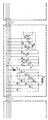
- the figure shows in a partially schematic representation an embodiment of a circuit according to the teaching of the invention using a circuit in an iron rail car.
- the circuit according to the invention is shown in the middle carriage, but is also found in the neighboring carriages, which are connected to one another via cables 23 and 24.
- the voltage of the first DC voltage source 1 is via the two-pole switches 2,2a; 3.3a and 4.4a with the specified polarity placed on the wires 9 - 12 via which the relays 6, 7 and 8, which act as electrically operated switches, respond in all cars and carry out the desired switching operations in accordance with the further switching arrangement.
- a further two-pole switch 13, 13b in the form of a pushbutton switch is provided, which applies the voltage of the DC voltage source 1 to the function-specific wires 9 and 10 in a polarity that deviates from the international agreement, via a current-limiting inductor 25, and in this way in all carriages via the cables 23 and 24 respond to the relays 5 serving as further switches which trigger further switching operations.
- a further pair of contacts 13a is provided, which opens when the switch 13, 13b is actuated.
- a transmitter fed from a further DC voltage source 18 is applied to the wires 10 and 11, said transmitter having an output stage 19 and a current limiting device 20.
- digital, also process-controlled data can be sent and transmitted via cable 23 and 24 to all carriages of the train association.
- a receiver is connected to the same function-specific wires 10 and 11 in all cars, which contains an optocoupler 22 and a polarity-determined diode 21, so that the data can be received and evaluated in all cars.
- the diodes 14, 15 and 16 are used to decouple the switching commands for door control and train lighting.
- S o can be Weglaufan Attacher externally and internally set on the carriage by liquid crystal display 35 or dot-matrix via a magnetic card reader.
- the compartments can be visibly displayed, in part by querying the individual passenger, train route, car number, reserved seats, stopping and transfer options, train speed, delays and time.
Landscapes
- Physics & Mathematics (AREA)
- General Physics & Mathematics (AREA)
- Train Traffic Observation, Control, And Security (AREA)
- Cable Transmission Systems, Equalization Of Radio And Reduction Of Echo (AREA)
- Communication Cables (AREA)
Abstract
Description
Gegenstand der Erfindung ist eine Schaltung zur Mehrfachausnutzung eines mehradrigen Kabels, das in Reihe zwei oder mehrere gleiche Stationen verbindet und über das in größeren zeitlichen Abständen mit Gleichspannung für kurze Zeit von einer Station aus mit zweipoligen Schaltern Schaltbefehle an eine Gruppe von elektrisch betätigten Schaltern zur Auslösung von Schaltvorgängen in jeder Station gegeben werden, wobei stets ein und dieselbe Ader des Kabels an dem einen Pol der ersten Gleichspannungsquelle und je nach dem auszuführenden Schaltvorgang eine andere, funktionsbestimmte Ader an den anderen Pol der ersten Gleichspannungsquelle gelegt wird und nach Durchführung des Schaltvorganges alle Adern potentialfrei sind.The invention relates to a circuit for multiple use of a multi-core cable, which connects two or more identical stations in series and over which, at larger time intervals with direct voltage, switching commands from a station with two-pole switches to a group of electrically operated switches for triggering of switching operations are given in each station, whereby one and the same wire of the cable is always connected to one pole of the first DC voltage source and, depending on the switching operation to be carried out, a different, function-specific wire is connected to the other pole of the first DC voltage source and all wires are carried out after the switching operation are potential free.
Kabel, die auf die eingangs beschriebene Art benutzt werden, sind zum Beispiel in Eisenbahnzügen gebräuchlich. Hier liegt auch ein besonders günstiges Anwendungsgebiet für die vorliegende Erfindung. Die Eisenbahnwagen führen durchlaufende, 12-adrige Kabel und werden untereinander durch 12-adrige Kabel zu einer Reihe von Stationen verbunden, so daß sich durch den ganzen Zug eine durchgehende Verbindung ergibt. Gemäß internationaler Vereinbarungen im Rahmen der UIC werden diese Kabel wie folgt genutzt:Cables that are used in the manner described at the beginning are used, for example, in railroad trains. This is also a particularly advantageous field of application for the present invention. The railway wagons run continuous, 12-core cables and are connected to each other by 12-core cables to a number of stations, so that there is a continuous connection through the whole train. According to international agreements within the UIC, these cables are used as follows:
Die erste bis achte Ader dienen der Übermittlung von Durchsagen, Musik oder dem Fernsprechverkehr zwischen Lokomotive und Zugführer, die neunte bis zwölfte Ader dienen dem Ein- und Ausschalten der Beleuchtung sowie dem Schließen der Türen. Dabei ist die zwölfte Ader stets mit dem Minus-Pol der Gleichspannungsquelle verbunden. Die neunte Ader überträgt den Befehl "Licht ein", die zehnte Ader den Befehl "Licht aus" und die elfte Ader den Befehl zum Schließen der Türen. Dazu werden diese funktionsbestimmten Adern mit dem Plus-Pol der Gleichspannungsquelle verbunden. Die Befehle werden mit zweipoligen Schaltern an Relais gegeben, die als elektrisch betätigte Schalter den gewünschten Schaltvorgang einleiten. Die Adern führen also nur während der Befehlsphase Spannung. Die Ausnutzung der Adern ist also sowohl hinsichtlich der Anzahl und der Häufigkeit als auch hinsichtlich der Zeitdauer sehr gering.The first to eighth wires are used to transmit announcements, music or telephone traffic between the locomotive and the train driver, the ninth to twelfth wires are used to switch the lighting on and off and to close the doors. The twelfth wire is always connected to the minus pole of the DC voltage source. The ninth wire transmits the "light on" command, the tenth wire the "light off" command and the eleventh wire the command to close the doors. For this purpose, these function-specific wires are connected to the positive pole of the DC voltage source. The commands are given to two-pole switches on relays, which initiate the desired switching process as electrically operated switches. The wires are only live during the command phase. The use of the cores is therefore very low in terms of the number and frequency as well as the duration.
Der Erfindung liegt die Aufgabe zugrunde, derartige Verbindungen mit einer für die vorhandenen Schaltvorgänge sehr niedrig liegenden Ausnutzungsquote auch für andere Aufgaben und Funktionen nutzbar zu machen, zum Beispiel für weitere Schaltvorgänge oder digitale Datenübertragungen.The object of the invention is to make such connections usable for other tasks and functions with a utilization rate which is very low for the existing switching processes, for example for further switching processes or digital data transmissions.
Die Lösung der Aufgabe erfolgt erfindungsgemäß dadurch, daß an je zwei der funktionsbestimmten Adern elektrische Bauelemente angeschlossen sind,über die ebenfalls mit Gleichstrom andere Schaltbefehle, Meldungen oder Informationen übertragen werden können.The object is achieved according to the invention in that electrical components are connected to two of the function-specific wires, via which other switching commands, messages or information can also be transmitted with direct current.
Dies kann in einer erfindungsgemäßen Ausführungsform derart geschehen, daß die erste Gleichspannungsquelle über einen weiteren zweipoligen Schalter und über zwei funktionsbestimmte Adern an einem weiteren Schalter liegt und zur Vermeidung von Nebenschlüssen oder Überlagerungen über die erste Gruppe elektrisch betätigter Schalter in den Zuleitungen zu den funktionsbestimmten Adern Dioden liegen. Diese erfindungsgemäße Ausführungsform kann noch vorteilhaft dahingehend ergänzt werden, daß die erste Gleichspannungsquelle über eine Strombegrenzung an eine funktionsbestimmte Ader angelegt ist und auch in der Leitung des weiteren Schalters zu einer funktionsbestimmten Ader eine Diode liegt. Über einen derartigen weiteren Schalter kann zum Beispiel die Auslösung der Notbremse verzögert werden.In an embodiment according to the invention, this can be done in such a way that the first DC voltage source is connected to a further switch via a further two-pole switch and via two function-specific wires and to avoid shunts or overlapping via the first group of electrically operated switches in the supply lines to the function-specific ones Cores are diodes. This embodiment according to the invention can advantageously be supplemented to the effect that the first DC voltage source is applied to a function-specific wire via a current limitation and that a diode also lies in the line of the further switch to a function-specific wire. The triggering of the emergency brake can be delayed, for example, via such a further switch.
Zur weiteren Sicherung liegt in der Zuleitung von der ersten Gleichspannungsquelle zu der funktionsbestimmten Ader, die bei Betätigung des weiteren zweipoligen Schalters die ersteGleichspannungsquelle kurzschließen könnte, ein zusätzliches, durch den weiteren zweipoligen Schalter betätigtes Kontaktpaar, das bei Betätigung des weiteren zweipoligen Schalters öffnet.For further protection, an additional pair of contacts actuated by the further two-pole switch, which opens when the further two-pole switch is actuated, lies in the supply line from the first DC voltage source to the functionally determined wire, which could short-circuit the first DC voltage source when the further two-pole switch is actuated.
In einer weiteren erfindungsgemäßen Ausfüh rungsform liegt an einem Paar funktionsbestimmter Adern in jeder Station ein aus einer zweiten Gleichspannungsquelle gespeister Sender und ein Empfänger.In a further embodiment according to the invention, a transmitter fed from a second DC voltage source and a receiver are located on a pair of functionally determined wires in each station.
Um zu verhindern, daß bei einer zufälligen gleichzeitigen Beschaltung der beiden Adern an denen der Sender liegt, dessen Ausgang kurzgeschlossen wird, ist in einer der funktionsbedingten Adern eine Diode vorgesehen.To prevent accidental simultaneous connection of the two wires to which the transmitter whose output is short-circuited, a diode is provided in one of the function-related wires.
Der Sender kann zum Beispiel zur Übertragung von Informationen aus einem abfragbaren Magnetspeicher dienen, während die Nutzung des Empfängers durch galvanische Entkopplung mit Hilfe eines Optokopplers an seinem Ausgang wesentlich erweitert werden kann.The transmitter can be used, for example, to transmit information from a magnetic memory that can be queried, while the use of the receiver can be significantly expanded by galvanic decoupling using an optocoupler at its output.
Die Figur zeigt in zum Teil schematischer Darstellung ein Ausführungsbeispiel einer Schaltung nach der Lehre der Erfindung anhand einer Schaltung in einem Eisenbahnwagen. Die erfindungsgemäße Schaltung ist im mittleren Wagen dargestellt, findet sich aber ebenso in den benachbarten Wagen, die untereinander über Kabel 23 und 24 verbunden sind. Die Spannung der ersten Gleichspannungsquelle 1 wird über die als Tastschalter ausgebildeten zweipoligen Schalter 2,2a; 3,3a und 4,4a mit der festgelegten Polarität an die Adern 9 - 12 gelegt über welche in allen Wagen die als elektrisch betätigte Schalter wirkenden Relais 6, 7 und 8 ansprechen und gemäß der weiteren Schaltanordnung die gewünschten Schaltvorgänge durchführen.The figure shows in a partially schematic representation an embodiment of a circuit according to the teaching of the invention using a circuit in an iron rail car. The circuit according to the invention is shown in the middle carriage, but is also found in the neighboring carriages, which are connected to one another via
Erfindungsgemäß ist ein weiterer als Tastschalter ausgebildeter zweipoliger Schalter 13,13b vorgesehen, der die Spannung der Gleichspannungsquelle 1 in einer von der internationalen Vereinbarung abweichenden Polarität über eine strombegrenzende Induktivität 25 an die funktionsbestimmten Adern 9 und 10 anlegt und dabei in allen Wagen über die Kabel 23 und 24 die als weitere Schalter dienenden Relai.s 5 ansprechen die weitere Schaltvorgänge auslösen. Zur Vermeidung von Kurzschlüssen ist ein weiteres Kontaktpaar 13a vorgesehen, das bei Betätigung des Schalters 13,13b öffnet.According to the invention, a further two-
In einer weiteren erfindungsgemäßen Ausführungsform ist an die Adern 10 und 11 ein aus einer weiteren Gleichspannungsquelle 18 gespeister Sender angelegt, der eine Endstufe 19 und eine Strombegrenzungseinrichtung 20 aufweist. Mit ihm können digitale, auch prozessgesteuerte Daten gesendet und über die Kabel 23 und 24 in alle Wagen des Zugverbandes übertragen werden. An die gleichen funktionsbestimmten Adern 10 und 11 ist in allen Wagen ein Empfänger angeschlossen, der einen Optokoppler 22 und eine polaritätsbestimmte Diode 21 enthält, so daß die Daten in allen Wagen empfangen und ausgewertet werden können. Die Dioden 14, 15 und 16 dienen den Entkopplungen gegenüber den Schaltbefehlen zur Türsteuerung und Zugbeleuchtung.In a further embodiment according to the invention, a transmitter fed from a further
Die durch die letztgenannte Ausbildung gebotenen Möglichkeiten der Nutzung sind sehr vielseitig. So können durch Flüssigkristallanzeige oder 35 Punkt-Matrix über einen Magnetkartenleser die Zuglaufanzeiger außen und innen am Wagen eingestellt werden. Auf die gleiche Weise können in den Abteilen sichtbar, zum Teil durch Abfrage vom einzelnen Fahrgast, Zuglauf, Wagennummer, reservierte Sitzplätze, Halte- und Umsteigemöglichkeiten, Geschwindigkeit des Zuges, Verspätungen und Uhrzeit angezeigt werden.The possibilities of use offered by the latter training are very diverse. S o can be Zuglaufanzeiger externally and internally set on the carriage by liquid crystal display 35 or dot-matrix via a magnetic card reader. In the same way, the compartments can be visibly displayed, in part by querying the individual passenger, train route, car number, reserved seats, stopping and transfer options, train speed, delays and time.
Ein weiterer Vorteil der erfindungsgemäßen Schaltung ist darin zu sehen, daß alle Wagen, die bereits entsprechend dem ersten Absatz der Beschreibung ausgestattet sind, gemäß der Erfindung nachgerüstet werden können.Another advantage of the circuit according to the invention can be seen in the fact that all cars that are already equipped according to the first paragraph of the description can be retrofitted according to the invention.
Claims (9)
dadurch gekennzeichnet,
daß an je zwei der funktionsbestimmten Adern (9,10,11) elektrische Bauelemente (13,13b,25;14,15;18,19,20;21,22) angeschlossen sind,übpr die ebenfalls mit Gleichstrom andere Schaltbefehle, Meldungen oder Informationen übertragen werden können.1.Circuit for multiple use of a multi-core cable, which connects two or more identical stations in series and over which, at longer intervals with DC voltage, switching commands from a station with two-pole switches for a short time to a first group of electrically operated switches for triggering switching operations be given in each station, whereby one and the same wire of the cable is always connected to one pole of the first DC voltage source and, depending on the switching process to be carried out, a different, function-specific wire of the cable is connected to the other pole of the DC voltage source and all wires are potential-free after the switching process has been carried out are,
characterized,
that on each two of the function specific cores (9,10,11) electrical components (13,13b, 25; 21,22 14,15;; 18,19,20) are connected, üb p r which also other with direct current switching commands, Messages or information can be transmitted.
dadurch gekennzeichnet,
daß die erste Gleichspannungsquelle (1) über einen weiteren zweipoligen Schalter (13,13b) und über zwei funktionsbestimmte Adern (9,10) an einem weiteren Schalter (5) liegt und zur Vermeidung von Nebenschlüssen oder Überlagerungen über die erste Gruppe elektrisch betätigter Schalter (6,7,8) in den Zuleitungen zu den funktionsbestimmten Adern (9,10,11) Dioden (15,16,17) liegen.2. Circuit according to claim 1,
characterized,
that the first DC voltage source (1) is connected to a further switch (5) via a further two-pole switch (13, 13b) and via two function-specific wires (9, 10) and to avoid shunts or overlapping via the first group of electrically operated switches ( 6,7,8) in the leads to the functionally determined wires (9,10,11) diodes (15,16,17).
dadurch gekennzeichnet,
daß die erste Gleichspannungsquelle (l) über eine Strombegrenzung (25) an eine funktionsbestimmte Ader (10) angelegt ist.3. Circuit according to claim 2,
characterized,
that the first DC voltage source (1) is applied to a functionally determined wire (10) via a current limitation (25).
dadurch gekennzeichnet,
daß auch in der Leitung des weiteren Schalters (5) zu einer funktionsbestimmten Ader (9) eine Diode (14) liegt.4. Circuit according to claim 2 or 3,
characterized,
that a diode (14) is also in the line of the further switch (5) to a function-specific wire (9).
dadurch gekennzeichnet,
daß in die Zuleitung von der ersten Gleichspannungsquelle (1) zu der funktionsbestimmten Ader (10), die bei Betätigung des weiteren zweipoligen Schalters (13,13b) die erste Gleichspannungsquelle kurzschließen könnte, ein zusätzliches, durch den weiteren zweipoligen Schalter (13,13b) betätigtes Kontaktpaar (13a) liegt, das bei Betätigung des weiteren zweipoligen Schalters (13,13b) öffnet.5. Circuit according to claim 2, 3 or 4,
characterized,
that in the supply line from the first DC voltage source (1) to the functionally-defined wire (10), which could short-circuit the first DC voltage source when the further two-pole switch (13, 13b) is actuated, an additional, through the further two-pole switch (13, 13b) actuated contact pair (13a), which opens when the further two-pole switch (13, 13b) is actuated.
daß an einem Paar funktionsbestimmter Adern(10,11) in jeder Station ein aus einer zweiten Gleichspannungsquelle (18) gespeister Sender (19,20) und ein Empfänger (21,22) liegt.6. Circuit according to claim 1 or one of the following, characterized in that
that a pair of functionally determined wires (10, 11) in each station has a transmitter (19, 20) and a receiver (21, 22) fed from a second DC voltage source (18).
dadurch gekennzeichnet,
daß in einer Zuleitung von der ersten Gleichspannungsquelle (1) zu einer der funktionsbestimmten Adern (11) eine Diode (26) liegt, die den Kurzschluß des Senderausganges bei gleichzeitiger Betätigung beider zweipoliger Schalter (2,2a;3,3a) verhindert.7. Circuit according to claim 6,
characterized,
that in a supply line from the first DC voltage source (1) to one of the functionally defined wires (11) there is a diode (26) which prevents the short circuit of the transmitter output while simultaneously actuating both two-pole switches (2,2a; 3,3a).
dadurch gekennzeichnet,
daß der Sender (19,20) mit abfragbaren Informationen aus einem Magnetspeicher gespeist werden kann.8. Circuit according to claim 7 or 8,
characterized,
that the transmitter (19, 20) can be fed with queryable information from a magnetic memory.
dadurch gekennzeichnet,
daß zur galvanischen Entkopplung am Ausgang des Empfängers ein Photokoppler (22) liegt.9. Circuit according to claim 6, 7. or 8,
characterized,
that a photocoupler (22) is located at the output of the receiver for galvanic decoupling.
Applications Claiming Priority (2)
| Application Number | Priority Date | Filing Date | Title |
|---|---|---|---|
| DE19853544976 DE3544976A1 (en) | 1985-12-19 | 1985-12-19 | CIRCUIT FOR MULTIPLE USE OF A MULTI-WIRE CABLE |
| DE3544976 | 1985-12-19 |
Publications (2)
| Publication Number | Publication Date |
|---|---|
| EP0226709A2 true EP0226709A2 (en) | 1987-07-01 |
| EP0226709A3 EP0226709A3 (en) | 1989-04-19 |
Family
ID=6288882
Family Applications (1)
| Application Number | Title | Priority Date | Filing Date |
|---|---|---|---|
| EP86112065A Withdrawn EP0226709A3 (en) | 1985-12-19 | 1986-09-01 | Circuit for the multiple use of a cable with a plurality of conductors |
Country Status (4)
| Country | Link |
|---|---|
| EP (1) | EP0226709A3 (en) |
| DD (1) | DD250804A5 (en) |
| DE (1) | DE3544976A1 (en) |
| YU (1) | YU199186A (en) |
Cited By (1)
| Publication number | Priority date | Publication date | Assignee | Title |
|---|---|---|---|---|
| EP0282067A3 (en) * | 1987-03-13 | 1989-04-26 | Gez Gesellschaft Fur Elektrische Zugausrustung Mbh | Circuit for the application of direct current voltage signals to a cable with a plurality of conductors |
Families Citing this family (1)
| Publication number | Priority date | Publication date | Assignee | Title |
|---|---|---|---|---|
| DE3803713C2 (en) * | 1988-02-08 | 1996-05-23 | Claas Ohg | Computer I / O circuitry |
Family Cites Families (4)
| Publication number | Priority date | Publication date | Assignee | Title |
|---|---|---|---|---|
| US2719927A (en) * | 1952-04-18 | 1955-10-04 | Courtney James | Electrical control systems and control devices therefor |
| DE1132957B (en) * | 1959-07-20 | 1962-07-12 | Hagenuk Neufeldt Kuhnke Gmbh | Circuit arrangement for optional remote-controlled switching on or off |
| GB1282657A (en) * | 1970-04-10 | 1972-07-19 | Jaguar Cars | Electrical supply system |
| DE2409930B2 (en) * | 1974-03-01 | 1977-10-13 | Sem Schwyz Gmbh, Schwyz (Schweiz) | SIGNAL TRANSMISSION CIRCUIT FOR ELECTRIC LOW CURRENT SIGNALS |
-
1985
- 1985-12-19 DE DE19853544976 patent/DE3544976A1/en not_active Withdrawn
-
1986
- 1986-09-01 EP EP86112065A patent/EP0226709A3/en not_active Withdrawn
- 1986-11-19 DD DD29642986A patent/DD250804A5/en not_active IP Right Cessation
- 1986-11-21 YU YU199186A patent/YU199186A/en unknown
Cited By (1)
| Publication number | Priority date | Publication date | Assignee | Title |
|---|---|---|---|---|
| EP0282067A3 (en) * | 1987-03-13 | 1989-04-26 | Gez Gesellschaft Fur Elektrische Zugausrustung Mbh | Circuit for the application of direct current voltage signals to a cable with a plurality of conductors |
Also Published As
| Publication number | Publication date |
|---|---|
| DE3544976A1 (en) | 1987-06-25 |
| YU199186A (en) | 1988-04-30 |
| DD250804A5 (en) | 1987-10-21 |
| EP0226709A3 (en) | 1989-04-19 |
Similar Documents
| Publication | Publication Date | Title |
|---|---|---|
| EP0226709A2 (en) | Circuit for the multiple use of a cable with a plurality of conductors | |
| DE2846801C2 (en) | Control system for track-guided model vehicles | |
| DE3139068C2 (en) | ||
| DE10008403C1 (en) | Power supply for driving a switch in DC rail networks, in particular for section isolating switches | |
| DE4131166A1 (en) | DEVICE FOR EXCHANGING DATA BETWEEN SEVERAL RAIL-MOUNTED MOVABLE MACHINES FOR THE OPERATION OF SEVERAL DIVERSE TEXTILE MACHINES AND A CONTROL CENTER | |
| DE2442659A1 (en) | Control system for conveyor installation - has individual control stations connected to vehicle and to common central station | |
| DE1009224C2 (en) | Device for central line block monitoring by means of axis counting | |
| DE2117819A1 (en) | Process for the transmission of information in telecontrol systems | |
| DE2720774C2 (en) | Circuit arrangement for the exchange of information between decentralized devices and a central control of a telephone exchange system | |
| DE3519222A1 (en) | Remote-control device for railway safety systems | |
| DE472301C (en) | Electrical signaling device for tram trains | |
| DE2440400C3 (en) | Arrangement for switching circuits on and off | |
| DE889901C (en) | Circuit arrangement for conference teleprinting systems operated with double current | |
| DE922955C (en) | Automatic signaling system for vacant and occupied display of single-track sections of electric railways | |
| DD139772B1 (en) | CIRCUIT ARRANGEMENT FOR TRANSFERRING INFORMATION ON A CONTROL SYSTEM | |
| DE874017C (en) | Arrangement for message transmission and control of vehicles by means of high frequency | |
| DE905148C (en) | Arrangement for carrier current transmission over the contact wire line in electrical rail operations | |
| DE814482C (en) | Device for the use of an electrical bifilar circuit for the purpose of separate or simultaneous switching of two independent electrical circuits and their use in particular for the production of electrically operated toys | |
| DE1001312C2 (en) | Control for electrical rail or contact line switches in a given adjustment sequence | |
| DE1462863C3 (en) | Receiving and forwarding arrangement for telecommunication signals according to the start-stop principle | |
| DE210861C (en) | ||
| EP0282067B1 (en) | Circuit for the application of direct current voltage signals to a cable with a plurality of conductors | |
| AT299302B (en) | Signaling device for monitoring the operational readiness of cable cars | |
| DE2443818A1 (en) | MESSAGE TRANSMISSION SYSTEM FOR NON-CENTRALLY STEERED RAILWAY RADIO SYSTEMS | |
| DE3329566A1 (en) | Telecontrol system |
Legal Events
| Date | Code | Title | Description |
|---|---|---|---|
| PUAI | Public reference made under article 153(3) epc to a published international application that has entered the european phase |
Free format text: ORIGINAL CODE: 0009012 |
|
| AK | Designated contracting states |
Kind code of ref document: A2 Designated state(s): AT BE CH DE FR IT LI NL |
|
| ITCL | It: translation for ep claims filed |
Representative=s name: BARZANO' E ZANARDO ROMA S.P.A. |
|
| EL | Fr: translation of claims filed | ||
| PUAL | Search report despatched |
Free format text: ORIGINAL CODE: 0009013 |
|
| AK | Designated contracting states |
Kind code of ref document: A3 Designated state(s): AT BE CH DE FR IT LI NL |
|
| STAA | Information on the status of an ep patent application or granted ep patent |
Free format text: STATUS: THE APPLICATION IS DEEMED TO BE WITHDRAWN |
|
| 18D | Application deemed to be withdrawn |
Effective date: 19891020 |
|
| RIN1 | Information on inventor provided before grant (corrected) |
Inventor name: KNAU, UDO, DIPL.-ING. Inventor name: KLUSACEK, MICHAEL, DIPL.-ING. Inventor name: BUERGIN, PETER, DIPL.-ING. |