EP0225632A2 - Method and apparatus for integrated sampling and in-line sample splitting of disperse products from transport pipes or to product stream transfer stations - Google Patents
Method and apparatus for integrated sampling and in-line sample splitting of disperse products from transport pipes or to product stream transfer stations Download PDFInfo
- Publication number
- EP0225632A2 EP0225632A2 EP86117097A EP86117097A EP0225632A2 EP 0225632 A2 EP0225632 A2 EP 0225632A2 EP 86117097 A EP86117097 A EP 86117097A EP 86117097 A EP86117097 A EP 86117097A EP 0225632 A2 EP0225632 A2 EP 0225632A2
- Authority
- EP
- European Patent Office
- Prior art keywords
- sample
- stream
- sampling
- partial
- analysis
- Prior art date
- Legal status (The legal status is an assumption and is not a legal conclusion. Google has not performed a legal analysis and makes no representation as to the accuracy of the status listed.)
- Granted
Links
Images


Classifications
-
- G—PHYSICS
- G01—MEASURING; TESTING
- G01N—INVESTIGATING OR ANALYSING MATERIALS BY DETERMINING THEIR CHEMICAL OR PHYSICAL PROPERTIES
- G01N1/00—Sampling; Preparing specimens for investigation
- G01N1/02—Devices for withdrawing samples
- G01N1/10—Devices for withdrawing samples in the liquid or fluent state
- G01N1/20—Devices for withdrawing samples in the liquid or fluent state for flowing or falling materials
- G01N2001/2092—Cross-cut sampling
-
- G—PHYSICS
- G01—MEASURING; TESTING
- G01N—INVESTIGATING OR ANALYSING MATERIALS BY DETERMINING THEIR CHEMICAL OR PHYSICAL PROPERTIES
- G01N1/00—Sampling; Preparing specimens for investigation
- G01N1/02—Devices for withdrawing samples
- G01N1/22—Devices for withdrawing samples in the gaseous state
- G01N1/2247—Sampling from a flowing stream of gas
- G01N2001/225—Sampling from a flowing stream of gas isokinetic, same flow rate for sample and bulk gas
Definitions
- the development step for on-line production control with the aim of process control ultimately requires a removal interface with which it is possible to quickly process e.g. a few minutes to have a small amount of analysis sample that is not only representative but also quantitative for analysis.
- a systematic classification of the conceivable types of withdrawal for disperse products must distinguish between production processes in which the product is transported in a fluid carrier stream, which can be wet (water) or dry - (air), or as separated, carrier-free bulk material, e.g. behind the cyclone, mill, sifter, bunker or the like and is delivered from a transport line or a chute or from a conveyor belt or handed over for further processing.
- a fluid carrier stream which can be wet (water) or dry - (air), or as separated, carrier-free bulk material, e.g. behind the cyclone, mill, sifter, bunker or the like and is delivered from a transport line or a chute or from a conveyor belt or handed over for further processing.
- sampling devices e.g. Pipette, piercer or sample lifter, immersion collector, sampling valve, stationary suction probe, sample probe, sample scraper, pendulum or impact sampler, half-open slotted sampling tube or screw conveyor, each of which only records a small part of the cross-sections of the production flow to be recorded, are for the complex tasks in on -line operation not suitable or only suitable to a limited extent.
- sampling devices which are available at product handover points, e.g. the transfer from one conveyor belt to another conveyor belt, as so-called slot samplers are intermittently moved back and forth under the product transfer point and represent a problem solution for this level, linear removal problem that can be used for less demanding applications if the division ratio does not exceed 1: 100.
- the invention has for its object to provide a method and an apparatus for sampling from streams of dispersed products from transport lines or at product transfer points and sample division on a representative small sample stream suitable for a subsequent on-line sample analysis.
- a continuous and representative sampling of up to 1/100 of the main product flow takes place in a rotationally symmetrical transport cross-section of the Production process.
- the use of a circular sector-shaped removal opening that radially sweeps over the entire transport cross-section ensures that all areas of the transport cross-section are taken into account representatively during sampling and that a sufficiently large partial sample (up to 1/100 of the main product stream) is taken integrally so that it is connected downstream in the line
- Sample dividers can also be temporally representative divided down to the small sample mass flow required for a representative sample analysis in a ratio of up to 1: 1000. In this way, only the smallest sample stream required for the downstream sample analysis, which can be a grain size analysis, is led out of the process, while the remaining partial stream is immediately in. the process product stream or main product stream remains or is returned in this.
- the new method and the corresponding device solve the problem in such a way that, on average, at least one partial stream is continuously taken from the entire transport cross-section of the product and fed to the in-line sample division.
- the shape and time are adjusted for the removal of the partial flow from the main flow via a removal cross-section or a removal opening, the outer boundaries of which form a circular sector with the opening angle a, which slowly rotates with its sector tip around the pivot point located in the tube axis of the main product transport stream.
- the speed of rotation w is chosen only so high that there are no disruptive effects on the product flow. This means that sampling is representative of the cross-section.
- the extraction ratio of partial flow to main flow achieved is ⁇ I360 °.
- the radius of the circular sector must be at least equal to or greater than the radius of the cylindrical transport line for the main stream, so that all the area components are completely covered within one revolution.
- One full revolution corresponds to an integration across the entire main stream transport cross section.
- the speed of rotation must not coincide with any fluctuation frequencies of the main stream.
- two opposite circular sectors can also be designed as a removal opening.
- the extraction ratio is 2 «/ 360 ° if the angles are the same or (a, + (2) / 360 ° if different sector angles are used.
- the integration effect may be discontinuous. This is avoided by attaching a cone-shaped tip or a deflection cone, which is so large in the circular base that the smallest sector-shaped removal opening close to the fulcrum is considerably larger in the tangential direction, preferably at least ten times larger than the dimensions corresponds to the coarsest particles contained in the main product stream.
- the deflection cone is to be made as steep as the deflection cone over which it is arranged so that the particles hitting the immediate center are easily removed and, on average, are representatively directed into the removal opening. This also prevents jamming of coarse particles in the inlet opening.
- a sieve with large meshes can also be provided between the main line and the intermediate piece to make it even.
- the invention allows a direct adaptation of the extraction of the analysis sample to the measuring ability of the on-line analysis system for the representative assessment of the product or process.
- the on-line analysis system used thus allows the process apparatus to be controlled and the analysis device to be connected to a continuously operating system in such a way that the validity and meaningfulness of the analysis results is not questionable about the function of the system.
- a process signal is obtained as a continuous time average. Ergodicity is not a prerequisite, as is the case with a shear mean value determination, i.e. the taking of individual samples does not mean that the sampling frequency is also stochastic as a random process.
- Ergodicity is difficult to check in the production process and is usually not given anyway in the case of fluctuating influencing variables and measured variables which make online process control or regulation necessary.
- a sample measuring device that is ready to measure every 10 minutes cannot achieve representative analysis results if an analysis sample is supplied to it every 10 minutes, the quantity of which only corresponds to the amount required by the analysis device and completely ignores what has happened between the sampling times in the production process.
- the new device can basically have two different configurations.
- the first embodiment realizes the sampling method if the disperse products are contained in fluid transport means, that is to say conveyed in a carrier means.
- the second embodiment realizes the sampling of bulk goods in vertical transport lines or
- FIG. 1 shows a device for integrating sampling and in-line sample division with isokinetic fluid or. Carrier means suction
- a product main stream 1 flowing in a transport pipe meets a removal or in this case formed by a double sector.
- Mouth opening 10 of a rotatably mounted sampling head 12 of a sampler 9 which rotates slowly at the angular velocity ⁇ about the transport pipe axis and through which a partial stream 2 is removed from the main stream 1.
- a sensor 11 is provided in or immediately in front of the removal opening 10, which contains the measurement information for setting a suction unit 70, e.g. a suction fan, for the isokinetic suction of the means of transport.
- a suction unit 70 e.g. a suction fan
- the senor 11 can be a pressure bore with a subsequent capillary line, which measures the static pressure of the main flow and together with a second pressure bore tion in the suction pipe for measuring the static pressure in the partial flow provides the basic information on the isokinetic operation of sampling according to the known principle of differential pressure probes.
- the sensor 11 can be designed as a correlation element with which the correct removal speed for the partial flow to be extracted can be set by measuring the particle speeds in the main flow.
- correlation measuring points see two optical sensors connected in series in the flow direction, e.g. Glass fiber sensors, from whose signal structure the speeds can be deduced by means of a correlation method via the transit time shift.
- the cross section of the rotatably mounted, rotationally driven removal head 12 is deformed such that a transition cross section 13 from the rotating removal head 12 into a fixed circular-cylindrical removal line 30 is circular. From a manufacturing point of view, this is easily achieved with two triangular sheets, which are beaded in the respective axis of symmetry and folded at an angle (180-a), connected at the removal opening at the break point and covered with two conical half-shells, the half-shells connecting to a circular opening at the transition cross section 13 .
- the fixed, elongated, curved sampling line 30 of the sampler 9 directs the partial stream 2 from the main stream 1 to an in-line sample divider 60 comprising a cylindrical head piece 31 rotating during operation and a downstream cylindrical stator 32. Both the head piece 31 and the stator 32 are divided with fixed internals in the form of axially parallel partition walls into sector-shaped guide channels 33, which are then individually transferred to a concentrator 71 in order to obtain the analysis sample stream from the divided sub-stream 2.
- the removal head 12 and the rotating sample divider head piece 31 are driven by the same drive 14 (motor M), the gear ratios being chosen so that w2> ⁇ , without being an integral multiple, and w, again out of sync with a possible oscillation in the main stream 1 may be selected.
- the sample divider 60 comprising a rotating head piece 31 and a fixed stator 32 can, together with the concentrator 71, also be installed directly in a main line 72 behind the removal head 12. The drive would then be implemented at the transfer cross section at different speeds by a common gear 15.
- the concentrator 71 is designed in such a way that an analysis sample mass flow 3 required for the subsequent use can be preselected and set correctly by means of gradual combination. A remaining partial stream 4 is returned to the main stream 1 by the suction unit 70 or discarded.
- the representative sample sample flow stream 3, which has been taken and divided, is used in a measuring section for on-line particle size analysis.
- the sample stream After passing through a baffle disperser 80 supplied with compressed air, the sample stream is blown as free jet 81 through the measuring zone of a diffraction spectrometer 82.
- the widening free jet 81 is detected with a collecting funnel 83 and is returned to the main stream 1 either directly or via a separating cyclone 84.
- This separation in the cyclone 84, coupled with a flow filter 85, enables a conventional check of the measurement results achieved on-line.
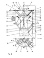
- FIG. 2 shows the device for carrying out the method behind a transport line or a chute with the two cuts E-E and A-D.
- a circular sector NMO can be seen in the left sector AMB as the rotating removal opening 10.
- the circular sector - encloses the angle between its corner points NO.
- the sector radius MN or MO is designed to be noticeably larger than the radius of the vertical main line or of the chute 72, which can be clearly seen in section E-E in section line A-B.
- the difference in diameter between the chute 72 and a sampler housing 16 is bridged with an intermediate piece 73. With the arrangement shown, all chute diameters that are smaller or equal to twice the sector radius MN can be equipped for sampling.
- the removal opening 10 is located on the inlet side of a mouth funnel 18 which tapers in the flow direction and serves as a removal head, on a hollow deflection cone 17 which is mounted so as to be drivable in a rotationally drivable manner counter to the direction of flow. This results in the outlet opening 19 which is crossed out in the top view AD.
- the partial stream 2 which is removed by it flows into an around the axis of the deflecting cone 17 with the angular velocity ⁇ 2 circulating manifold 20.
- the main mass flow 1 falling past the discharge opening 10 or the outlet funnel 18 is returned to the center of the fall by a fixed first collecting cone 21 and passed on to a rotatable second collecting cone 22 with a subsequent central pipe outlet 23.
- the distributor pipe 20- is firmly connected to the second collecting cone 22. This is set in rotation by a motor 14 via a drive belt 28 at the angular velocity c.l2. As a result, the distributor pipe 20 also rotates at this angular velocity 02.
- the drive is arranged here outside the housing 16, so that both the motor 14 and its drive belt 28 have no product contact.
- the encapsulation of the drive space between the housing 16 and the internals 17, 18, 20, 21, 22 and 23 is achieved by the special design of a sealing brush 27, which at the same time acts as a cleaning element between the first or upper collecting cone 21 and the second or lower collecting cone 22 acts.
- the driven elements 17, 18, 20, 22 and 23 are mounted centrally on a bearing block 29.
- the deflection cone 17 and the mouth funnel 18 are driven via a transmission which also serves as a connecting element, the lower half 15 of which is built into the distributor pipe 20 and the upper half 24 of which is built into the deflection cone 17, due to the rotation of the lower collecting cone 22.
- An integrated drive is shown in Fig. 5 and described by this.
- a cleaning brush 26 is fastened, which also rotates and keeps the first or upper stationary collecting cone 21 free of deposits on the inside and ensures a constant product outflow.
- the cleaning brush 26 is supported by the constant vibration of the device by means of a vibrator 51, as shown in FIG. 5.
- the rotating cleaning brush 26 lies opposite the mouth funnel 18 and is to be tared as a centrifugal mass so that the eccentric imbalance of the mouth funnel 18 is compensated for.
- a corresponding centrifugal mass 25 to compensate for the eccentric imbalance of the distributor pipe 20 is to be provided on the second or lower, rotating collecting cone 22. It itself is kept free of deposits in the upper inlet area by the sealing brush 27, which is supported on the outer surface of the first or upper collecting cone 21. and is fixed or does not turn.
- the free passage cross section between the collecting cones 21 and 22 can be closed with a correspondingly rotationally symmetrical brush arrangement. This is particularly important if, as shown, the second collecting cone 22 from the outside, e.g. by means of the drive belt 28, is rotated and the housing bushings and the drive elements should not have any product contact.
- a housing 34 of the downstream in-line sample divider is flanged to the sampler housing 16 below the cutting plane CD.
- the rotating distributor pipe 20 transfers the withdrawn partial flow 2 to a dividing funnel 35.
- a partial opening 36 in the inner surface of the dividing funnel which is sector-shaped and is delimited by the corner points RSTU.
- ⁇ / 360 ° of the partial flow can fall through, while a remaining partial flow 4 (1- ⁇ / 360 °) from the dividing funnel 35 through its outlet opening 35 'into a lower return pipe 37 to main mass flow 6 not taken is returned.
- the bearing block 29 is fastened to the return pipe 37.
- a slightly inclined safety sieve 38 is arranged below the partial opening 36, with which coarse spray particles 7, impurities or particles that lie outside the measuring range of the downstream sample analyzer can be separated from the analysis sample stream 3 and returned to the main pipe 6 in the return pipe 37.
- the analytical sample stream 3 thus prepared is directed into a sample delivery tube 39 and is led out of the combined sampler-sample divider for subsequent sample analysis or other use at the shaft transfer opening 40.
- Fig. 3 shows in section E-E a central deflection cone 59, which is arranged above the deflection cone 17, that it is completely housed in the intermediate piece 73 from the height and above it, a large-meshed intermediate sieve 61 can be installed for uniform transverse distribution of the falling bulk material stream 1.
- the base circles of the cones 59 and 17 arranged one above the other are shown as full circles in the plan view for clarity.
- FIG. 3 An intake port 51 is arranged around the central transfer pipe 52 in such a way that an adjustable annular gap 53 is created around the transfer cross section 40.
- a downstream suction unit 70 is the The smallest possible air flow required for dedusting is sucked in from the outside against and transversely to the direction of fall of the sample stream 3 through a filter 85.
- the opening angle ⁇ is variable and e.g. adjustable according to a mass flow sensor 8.
- the actual mass flow value leads via a signal line 79 to the setting of the opening angle ⁇ .
- FIG. 4 Two embodiments of variable setting options for the removal opening angle ⁇ are shown in FIG. 4.
- the top view representation of FIG. 2, sector AMB is repeated in the top view in the lower left quadrant. Removal opening 10, outlet opening 19 and deflection cone 17 can be seen.
- the setting of ⁇ , with folding chutes 41 is shown as the first embodiment.
- the three open chutes are crossed out at the passage openings.
- section A-A the triangular contour of the folding chutes 41 which are U-shaped in cross section can be seen in the top right in FIG. 4.
- the open position is shown in dashed lines.
- the closed position the open upper edge lies in the plane of the dividing funnel 35.
- the folding chute 41 pivots through the angle ⁇ from the closed position.
- the analysis sample stream 3 then passes through the safety sieve 38 into the sample delivery tube 39 to the transfer opening 40.
- the folding chutes 41 are closed, the residual partial stream 4 returns to the main mass flow 6 into the return pipe 37.
- the advantage of the chute arrangement is that it can be easily combined with digital control devices in which the opening or closing of individual folding chutes 41 can be switched discretely by simple yes / no decisions.
- the two upper quadrants of the lower part of FIG. 4 show a solution for a stepless adjustment of the analysis sample flow.
- the sample divider opening angle ⁇ 2 is set here by the rotation of a funnel segment 43. This is arranged in parallel above or below the dividing funnel 35 and can partially or completely cover the partial opening 36 of the dividing funnel 35 which is interrupted by 90 °.
- the discharged through the remaining portion of the opening 36 (ß 2) partial flow falls, as can be seen, before entering the left in section AA back to the safety screen 38 as an analysis sample flow 3 in the sample delivery tube 39 to the transfer opening 40th
- FIG. 5 shows a modified embodiment of a combined in-line sampler with a downstream sample divider.
- the sample divider here is a rotationally symmetrical corrugated divider arranged over the entire circumference.
- the partial mass flow 2 flowing out of the manifold 20 eccentrically is broken down along the entire orbit by a fixed fan collar of the corrugated divider into successive individual samples 5 of the same size.
- the horizontally consecutive compartments of the corrugated divider are arranged in such a way that all individual samples which are dropped onto an inwardly inclined long fan base 44 are returned to the main stream and all individual samples which fall on an outwardly inclined short fan base 45 as a divided analysis sample stream 3 subtracted from. In this way, every second individual sample 5 arrives at the analysis sample stream 3.
- the fixed division ratio of 1: 2 thus achieved is insensitive to mass flow fluctuations from the removal opening 10, since integration over the entire cross-section immediately compensates for sectoral overloads and underloads. For this reason, it is not necessary in this arrangement to operate the removal opening 10 at a different angular speed than the downstream distributor pipe 20 for the transfer to the sample divider.
- the design solution and the drive in the sampler are correspondingly simpler.
- Deflection cone 17, mouth funnel 18 with outlet opening 19 and distributor pipe 20 are connected to form a structural unit which is driven by the motor 14 via a gear 15 'at a constant angular velocity w.
- the drive via the motor 14 alternatively takes place from below, where. it is arranged protected together with the gear 15 'under a rotating conical hood 46.
- the driven elements 17, 18, 20, 22, 23, 25, 26 and 46 are rotatably mounted centrally on the bearing block 29.
- FIG. 6 Another embodiment of the security screening located outside of the sampler and divider housing 16, 60 is shown in FIG. 6.
- the cascade connection of the simple classifying elements 99 shown in FIG. 6 permits flexible adaptation, both to changing quantities and to different separation limits.
- Each element consists of two half-shells.
- An upper half-shell 86 has an inlet connection 88 at its upper end, which is flanged directly to the outlet connection 39 of the sample divider 60 in the top classifying element 99 in the side view in FIG. 6.
- This sieve is clamped between two half-shells 86 and 87 and is dimensioned such that the spray particles are retained as coarse material by the sieve, while the analyzable sample stream 3 passes through as fine material.
- the coarse material runs off via the safety sieve 38 and reaches the coarse material outlet connection 90 of a lower half-shell 87 in the lower part of a classifying element 99.
- the safety sieve 38 itself is shorter than the classifying element 99 and is so long that a fine material located further up Outlet port 89 of the lower half-shell 87 is completely covered and short-circuit currents are just avoided.
- the length and steepness of the classification elements are determined on the one hand by the permissible length of stay, which should be as short as possible, and on the other hand by the required selectivity. It is easy to adapt to this and to changing process conditions with classifying elements 99 designed in this way, in that classifying elements 99 of identical construction are now connected to the outlet connections 89 and 90 of the first lower half-shell 87. This leads to a re-screening of the fine as well as the coarse material of the first stage. Depending on the task, this sieve or a correspondingly adjusted sieve mesh size can be used in these downstream stages.
- the respective fine material of the downstream classification elements for the total fine material F or the analysis sample stream 3 without spray grain and the respective coarse material for the total coarse material G or for the amount of the spray grain parts are combined by means of suitable Y-pipe pieces.
- any other combinations of structurally identical classification elements 99 are conceivable.
- a very clear elimination of the spray grain would be achievable, for example, with a multiple series connection of classifying elements at the lower coarse material outlet, while the fine material could be composed of the respective passages at the upper fine material outlets without further reclassification.
- a finely divided fine material could be produced in a targeted manner.
- Another circuit variant could be set up with the aim of performing multiple classification.
- the mesh sizes of the safety sieve 38 would have to be graded accordingly in the case of the successive classification elements.
- the mesh sizes behind the fine material outlets would have to become increasingly smaller and the mesh sizes behind the coarse material outlets correspondingly larger.
- a multiple classification behind the sampling would, for example, be used for gravimetric analysis of the course of a particle size distribution outside the measuring range of a downstream sample analyzer.
- Variants for the simultaneous production of sharp classification cuts and for multiple classification can also be combined in series and in parallel.
- a double-acting vibration drive 51 installed between the classifying elements.
- Partial section A-D in FIG. 6 shows the assignment of the sieve cascade to the representations in FIGS. 2, 3 and 4.
- FIGS. 2 and 4 show the fan collar of the corrugated divider with the short fan bases 45 and the long fan bases 44, via which the individual samples 5 are returned to the main product stream 1.
Landscapes
- Life Sciences & Earth Sciences (AREA)
- Hydrology & Water Resources (AREA)
- Physics & Mathematics (AREA)
- Health & Medical Sciences (AREA)
- Chemical & Material Sciences (AREA)
- Analytical Chemistry (AREA)
- Biochemistry (AREA)
- General Health & Medical Sciences (AREA)
- General Physics & Mathematics (AREA)
- Immunology (AREA)
- Pathology (AREA)
- Sampling And Sample Adjustment (AREA)
- Analysing Materials By The Use Of Radiation (AREA)
Abstract
Description
Die Analyse von Produktqualitäten in Produktionsprozessen erfolgt insbesondere bei der Herstellung von Massengütern an Hand ausgewählter Teilproben, die aus dem Prozeß entnommen werden. Für die anschließenden Analysen im Labor werden meist nur geringe Probenmengen von wenigen Gramm oder sogar Milligramm benötigt, so daß sich die Aufgabe, kleinste, repräsentative Analysenprobenmengen aus großen Produktionsströmen von einigen Tonnen je Stunde zu entnehmen, reproduzierbar zuverlässig überhaupt nur lösen läßt, wenn zunächst größere Teilmengen entnommen und anschließend durch kontrollierte repräsentative Probenteilung die kleinen, erforderlichen Analysenprobenmengen gewonnen werden.The analysis of product qualities in production processes takes place in particular in the production of bulk goods on the basis of selected partial samples which are taken from the process. For the subsequent analyzes in the laboratory, usually only small sample quantities of a few grams or even milligrams are required, so that the task of extracting the smallest, representative sample quantities from large production streams of a few tons per hour can only be reproducibly and reliably achieved if initially larger ones Partial quantities are removed and the small, required analytical sample quantities are then obtained by controlled representative sample division.
Die sogenannte off-line Qualitätskontrolle bei dispersen Produkten stellt heute innerhalb von wenigen Stunden bis zu einem Tag ein Analysenergebnis zur Produktbeurteilung zur Verfügung. Allerdings erfolgt die Probenahme und Probenteilung i.allg. nur in zeitlichem Abstand und immer noch eher einfach. Sie muß hinsichtlich der Prozedur, der Reproduzierbarkeit und Systematik gerade auch im Vergleich zu den mittlererweile verfügbaren off-line Meßgeräten als die mit Abstand schwächste Stelle in der Informationskette zum Prozeß betrachtet werden, auch wenn schon erste kontinuierlich arbeitende Probenehmer angekündigt sind, mit denen sich jedoch unmittelbar keine Analysenprobenmengen gewinnen lassen. Diese Probenehmer würden daher höchstens quasi-kontinuierlich arbeiten, da auf sie die Anforderungen des ihnen nachgeordneten Analysegeräts übertragen werden.The so-called off-line quality control for disperse products provides an analysis result for product evaluation within a few hours to a day. However, sampling and sample division generally takes place. only at intervals and still rather simple. With regard to the procedure, the reproducibility and the systematics, it has to be regarded as by far the weakest point in the process information chain, even in comparison to the off-line measuring devices that are now available, even if the first continuously working samplers have already been announced, but with whom do not immediately obtain any analytical sample quantities. These samplers would therefore work at most quasi-continuously, since the requirements of the analysis device downstream of them are transferred to them.
Zunehmende Automation, Rationalisierung und verstetigte Qualitätskontrolle an Produktströmen lassen die in zeitlichen Abständen vorgenommene manuelle Stichprobenentnahme insbesondere wegen ihrer begrenzten Repräsentativität dann äußerst fragwürdig erscheinen, wenn die Laboranalysen mit hochgenauen Meßgeräten vorgenommen werden. Die Charakterisierung disperser Produkt eigenschaften durch zumindest quasi-kontinuierliche Partikelgrößenanalyse, z.B. mit einem Laser-Beugungsspektrometer, macht diese Diskrepanz mittlerweise besonders spürbar.Increasing automation, rationalization and constant quality control of product streams make manual sampling at intervals appear extremely questionable, especially because of their limited representativity, if the laboratory analyzes are carried out with highly precise measuring devices. The characterization of disperse product properties by at least quasi-continuous particle size analysis, e.g. With a laser diffraction spectrometer, this discrepancy is now particularly noticeable.
Der Entwicklungsschritt zur on-line-Produktionskontrolle mit dem Ziel der Prozeßsteuerung setzt schließlich eine Entnahmeschnittstelle voraus, mit der es möglich ist, innerhalb kurzer Zeitvon z.B. wenigen Minuten über eine kleine Analysenprobenmenge zu verfügen, die nicht nur repräsentativ sondern auch quantitativ für die Analyse geeignet ist.The development step for on-line production control with the aim of process control ultimately requires a removal interface with which it is possible to quickly process e.g. a few minutes to have a small amount of analysis sample that is not only representative but also quantitative for analysis.
Eine systematische Einteilung der denkbaren Entnahmearten für disperse Produkte muß zwischen Produktionsprozessen unterscheiden, bei denen das Produkt in einem fluiden Trägermittelstrom, der naß (Wasser) oder trocken - (Luft) sein kann, oder als abgeschiedenes, trägermittelfreies Schüttgut transportiert wird, wie es z.B. hinter Zyklon, Mühle, Sichter, Bunker oder dergl. vorliegt und aus einer Transportleitung oder einem Fallschacht oder von einem Förderband abgegeben oder zur weiteren Bearbeitung übergeben wird.A systematic classification of the conceivable types of withdrawal for disperse products must distinguish between production processes in which the product is transported in a fluid carrier stream, which can be wet (water) or dry - (air), or as separated, carrier-free bulk material, e.g. behind the cyclone, mill, sifter, bunker or the like and is delivered from a transport line or a chute or from a conveyor belt or handed over for further processing.
Die bekannten Probenahmegeräte, wie z.B. Pipette, Stech-oder Probenheber, Eintauchsammler, Probenahmeventile, stationäre Absaugsonden, Probenstecher, Probenabstreifer, Pendel-oder Schlagprobenehmer, halboffene geschlitzte Entnahmerohre oder Förderschnecken, die jeweils nur einen kleinen Teil der zu erfassenden Querschnitte des Produktionsstromes erfassen, sind für die komplexen Aufgaben im on-line Betrieb nicht oder höchstens bedingt geeignet.The known sampling devices, e.g. Pipette, piercer or sample lifter, immersion collector, sampling valve, stationary suction probe, sample probe, sample scraper, pendulum or impact sampler, half-open slotted sampling tube or screw conveyor, each of which only records a small part of the cross-sections of the production flow to be recorded, are for the complex tasks in on -line operation not suitable or only suitable to a limited extent.
Für den Fall der Bandübergabe sind Probenahmegeräte bekannt, die an Produktübergabestellen, z.B. der Übergabe von einem Förderband auf ein anderes Förderband, als sogenannte Schlitzprobenehmer intermittierend unter der Produktübergabestelle hin-und herbewegt werden und für dieses ebene, lineare Entnahmeproblem eine für weniger anspruchsvolle Anwendungsfälle anwendbare Problemlösung darstellen, wenn das Teilungsverhältnis nicht größer als 1:100 wird.In the case of the tape handover, sampling devices are known which are available at product handover points, e.g. the transfer from one conveyor belt to another conveyor belt, as so-called slot samplers are intermittently moved back and forth under the product transfer point and represent a problem solution for this level, linear removal problem that can be used for less demanding applications if the division ratio does not exceed 1: 100.
Bei rotationssymmetrischen Prozeßquerschnitten, die beim Transport von dispersen Produkten in einem nassen oder trockenen Transportmittel üblich sind (Transportleitungen), können bekannte intermittierende oder rotierende Schlitzprobennehmer jedoch nicht bei hohen Anforderungen an die Aussagegenauigkeit eingesetzt werden.In the case of rotationally symmetrical process cross sections, which are customary for the transport of disperse products in a wet or dry means of transport (transport lines), known intermittent or rotating slot samplers cannot be used, however, if the accuracy of the statement is high.
Der Erfindung liegt die Aufgabe zugrunde, ein Verfahren und eine Vorrichtung zur Probenahme aus Strömen disperser Produkte aus Transportleitungen oder an Produktübergabestellen und Probenteilung auf einen für eine anschließende on-line Probenanalyse geeigneten repräsentativen kleinen Analysenprobenstrom zu schaffen.The invention has for its object to provide a method and an apparatus for sampling from streams of dispersed products from transport lines or at product transfer points and sample division on a representative small sample stream suitable for a subsequent on-line sample analysis.
Verfahren und Vorrichtung, die diese Aufgabe lösen, sind mit ihren Ausgestältungen in den Ansprüchen gekennzeichnet.Methods and apparatus that solve this problem are characterized with their configurations in the claims.
Um den Anforderungen in einem on-line-Betrieb zu entsprechen, erfolgt eine kontinuierliche und repräsentative Probenahme von bis zu 1/100 des Produkthauptstroms in einem rotationssymmetrischen Transportquerschnitt des Produktionsprozesses. Dabei ist durch die Verwendung einer den ganzen Transportquerschnitt radial überstreichenden kreissektorförmigen Entnahmeöffnung sichergestellt, daß sämtliche Flächenanteile des Transportquerschnitts bei der Probenahme repräsentativ berücksichtigt werden und eine ausreichend große Teilprobe (bis 1/100 des Produkthauptstroms) intergrierend entnommen wird, damit in dem in-line nachgeschalteten Probenteiler auch zeitlich repräsentativ auf den für eine repräsentative Probenanalyse erforderlichen kleinen Analysenprobenmassestrom im Verhältnis von bis zu 1:1000 heruntergeteilt werden kann. Es wird auf diese Weise nur der für die nachgeordnete Probenanalyse, die eine Korngrößenanalyse sein kann, erforderliche kleinste Probenstrom aus dem Prozeß herausgeführt, während der übrigbleibende Restteilstrom unmittelbar in . dem Prozeßproduktstrom bzw. Produkthauptstrom verbleibt bzw. in diesen zurückgegeben wird.In order to meet the requirements in on-line operation, a continuous and representative sampling of up to 1/100 of the main product flow takes place in a rotationally symmetrical transport cross-section of the Production process. The use of a circular sector-shaped removal opening that radially sweeps over the entire transport cross-section ensures that all areas of the transport cross-section are taken into account representatively during sampling and that a sufficiently large partial sample (up to 1/100 of the main product stream) is taken integrally so that it is connected downstream in the line Sample dividers can also be temporally representative divided down to the small sample mass flow required for a representative sample analysis in a ratio of up to 1: 1000. In this way, only the smallest sample stream required for the downstream sample analysis, which can be a grain size analysis, is led out of the process, while the remaining partial stream is immediately in. the process product stream or main product stream remains or is returned in this.
Das neue Verfahren und die entsprechende Vorrichtung lösen die gestellte Aufgabe so, daß im zeitlichen Mittel aus dem gesamten Transportquerschnitt des Produktes kontinuierlich mindestens ein Teilstrom repräsentativ entnommen und der in-line nachgeschalteten Probenteilung zugeführt wird. Dies wird dadurch erreicht, daß der Öffnungsquerschnitt zur Entnahme des Teilstroms sowohl von der Form als auch von seiner zeitlichen Lage der örtlichen und zeitlichen Entnahmesituation anpaßbar ist.The new method and the corresponding device solve the problem in such a way that, on average, at least one partial stream is continuously taken from the entire transport cross-section of the product and fed to the in-line sample division. This is achieved in that the opening cross-section for the removal of the partial flow can be adapted to the local and temporal removal situation both in terms of the shape and in terms of its position in time.
Konventionelle Teilstrom-Probenahmeverfahren, wie z.B. die Absaugung mit Sonden gemäß VDI-Richtlinie 2066, tasten den Produktstromquerschnitt punktweise nach einem vorgegebenen Raster in durch das Probenanalysengerät gesteuertem zeitlichen Abstand traversierend ab. Dieses Probennahmeverfahren verfügt weder über ein hohes, lokales Auflösungsvermögen noch über eine aussagekräftige Integrationswirkung in bezug auf den gesamten Transportquerschnitt, da die Gewichtung der einzelnen Entnahmepunkte von hypothetischen Annahmen über die Qualität der quasistationären Anströmung und die Homogenität der Verteilung des dispersen Produkts im Transportquerschnitt und über die Zeit ausgehen muß.Conventional partial flow sampling methods, e.g. suction with probes according to VDI guideline 2066, traverse the product flow cross-section point-by-point according to a predetermined grid at a time interval controlled by the sample analyzer. This sampling method has neither a high, local resolving power nor a meaningful integration effect with regard to the entire transport cross-section, since the weighting of the individual sampling points from hypothetical assumptions about the quality of the quasi-steady flow and the homogeneity of the distribution of the dispersed product in the transport cross-section and about the Time must run out.
Es erfolgt die Anpassung nach Form und Zeit zur Entnahme des Teilstromes aus dem Hauptstrom über einen Entnahmequerschnitt bzw. eine Entnahmeöffnung, deren äußere Begrenzungen einen Kreissektor mit dem Öffnungswinkel a bilden, der mit seiner Sektorspitze um den in der Rohrachse des Produkthaupttransportstroms liegenden Drehpunkt langsam rotiert. Die Drehgeschwindigkeit w wird nur so hoch gewählt, daß keine störenden Rückwirkungen auf den Produktstrom entstehen. Dadurch ist die Probenentnahme repräsentativ in Bezug auf den Entnahmequerschnitt.The shape and time are adjusted for the removal of the partial flow from the main flow via a removal cross-section or a removal opening, the outer boundaries of which form a circular sector with the opening angle a, which slowly rotates with its sector tip around the pivot point located in the tube axis of the main product transport stream. The speed of rotation w is chosen only so high that there are no disruptive effects on the product flow. This means that sampling is representative of the cross-section.
Das erzielte Entnahmeverhältnis von Teilstrom zum Hauptstrom beträgt αI360°. Der Radius des Kreissektors muß mindestens gleich oder größer als der Radius der zylindrischen Transportleitung für den Hauptstrom sein, damit alle Flächenanteile innerhalb einer Umdrehung einmal vollständig erfaßt werden. Eine volle Umdrehung entspricht einer Integration über den gesamten Hauptstrom-Transportquerschnitt. Die Rotationsgeschwindigkeit darf nicht mit eventuellen Schwankungsfrequenzen des Hauptstromes übereinstimmen. Mit der Anzahl der Integrationszyklen, aus denen die gesamte Teilprobe summarisch gebildet wird, steigt deren Zuverlässigkeit zur Beurteilung des .Produktstromes.The extraction ratio of partial flow to main flow achieved is αI360 °. The radius of the circular sector must be at least equal to or greater than the radius of the cylindrical transport line for the main stream, so that all the area components are completely covered within one revolution. One full revolution corresponds to an integration across the entire main stream transport cross section. The speed of rotation must not coincide with any fluctuation frequencies of the main stream. With the number of integration cycles, from which the entire partial sample is formed summarily, its reliability for assessing the product flow increases.
Statt eines einzigen Kreissektors können auch zwei sich gegenüberliegende Kreissektoren als Entnahmeöffnung ausgebildet sein. Das Entnahmeverhältnis beträgt dann 2«/360°, wenn die Winkel gleich sind bzw. (a, + (2)/360°, wenn unterschiedliche Sektorwinkel zur Anwendung kommen.Instead of a single circular sector, two opposite circular sectors can also be designed as a removal opening. The extraction ratio is 2 «/ 360 ° if the angles are the same or (a, + (2) / 360 ° if different sector angles are used.
Insbesondere bei groben Partikeln im Produkthauptstrom kann es zur Unstetigkeit in der Integrationswirkung kommen. Dies vermeidet man durch den Aufsatz einer konusförmigen Spitze bzw. eines Abweisekonus, die bzw. der in der kreisförmigen Basis so groß ausgeführt wird, daß die kleinste, nahe beim Drehpunkt liegende sektorförmige Entnahmeöffnung in tangentialer Richtung erheblich größer, vorzugsweise wenigstens zehnmal größer als die Abmessungen der gröbsten im Produkthauptstrom enthaltenen Partikeln entspricht..In the case of coarse particles in the main product flow, the integration effect may be discontinuous. This is avoided by attaching a cone-shaped tip or a deflection cone, which is so large in the circular base that the smallest sector-shaped removal opening close to the fulcrum is considerably larger in the tangential direction, preferably at least ten times larger than the dimensions corresponds to the coarsest particles contained in the main product stream.
Der Abweisekonus ist dabei so steil auszuführen wie der Ablenkkonus, über dem er angeordnet ist, so daß die im unmittelbaren Zentrum auftreffenden Partikel ohne weiteres abgeführt und im Mittel repräsentativ in die Entnahmeöffnung geleitet werden. Außerdem wird so ein Verklemmen grober Partikel in der Eintrittsöffnung verhindert. Zur Vergleichmäßigung kann zusätzlich zwischen der Hauptleitung und dem Zwischenstück ein Sieb mit großen Maschen vorgesehen werden.The deflection cone is to be made as steep as the deflection cone over which it is arranged so that the particles hitting the immediate center are easily removed and, on average, are representatively directed into the removal opening. This also prevents jamming of coarse particles in the inlet opening. A sieve with large meshes can also be provided between the main line and the intermediate piece to make it even.
Mit on-line-Meßzyklen von ca. 5 Minuten Dauer werden bei einer Meßzeit von einer Minute und stetiger Probenahme im Mittel Teilmengen aus 100 bis 200 Integrations-Umdrehungen erhalten, wenn die Drehgeschwindigkeit bis zu 1/2 Umdrehung pro Sekunde beträgt. Da die Ausbildung der Entnahmeöffnung mit Sektoröffnungswinkeln a unter 5° wegen der Zunahme der Umrandungseinflüsse bei kleinen Winkeln technisch nicht zu empfehlen ist, sollte der Entnahme-Teilstrom wenigstens etwa 1,5 % des Produkthauptstromes betragen. Die erforderliche kontinuierliche Reduzierung auf einen Analysenprobenstrom wird mit dem unmittelbar nachgeschalteten Probenteiler verwirklicht. Als Orientierung kann gelten, daß zur on-line-Analyse zwischen 1 % und 0,001 % des Produkthauptstromes benötigt werden, wobei, wie oben ausgeführt, die Probenahme den Teilungsschritt in den Prozentbereich leisten kann und die anschließende in-line-Probenteilung des Teilstroms durch entsprechende Ausgestaltung die weitere Reduzierung um zusätzlich zwei bis drei Zehnerpotenzen repräsentativ leisten muß.With on-line measuring cycles of approx. 5 minutes in duration with a measuring time of one minute and constant sampling, on average partial quantities from 100 to 200 integration revolutions are obtained if the rotational speed is up to 1/2 revolutions per second. Since the formation of the removal opening with sector opening angles a below 5 ° is not technically recommended due to the increase in the border influences at small angles, the removal partial flow should be at least about 1.5% of the main product flow. The required continuous reduction to one Analysis sample stream is realized with the immediately downstream sample divider. As a guide, it can be considered that between 1% and 0.001% of the main product flow is required for the on-line analysis, whereby, as explained above, the sampling can perform the dividing step in the percentage range and the subsequent in-line sample division of the partial flow by appropriate The further reduction by an additional two to three powers of ten must be representative.
Dies kann so verwirklicht werden, daß der mit der Kreissektor-Entnahmeöffnung entnommene kontinuierliche Teilstrom in eine diskrete Folge von Teilströmen aufgespalten wird, die als Einzelströme durch ausgewählte Zusammenfassung, z.B. jedes 8., 16. oder 32. usw. Einzelstroms zuletzt zum Analysenprobenstrom zusammengefaßt werden. Durch die starke Unterteilung in zunächst hunderte von Einzelströmen und die systematische Durchführung der Stichprobensammlung ist nur noch mit sehr kleinen systematischen Fehlern zu rechnen.This can be realized in such a way that the continuous partial stream withdrawn with the circular sector removal opening is split into a discrete sequence of partial streams, which as individual streams by selected combination, e.g. every 8th, 16th or 32nd etc. individual stream are finally combined to form the analysis sample stream. Due to the strong subdivision into hundreds of individual streams and the systematic implementation of the sample collection, only very small systematic errors can be expected.
Die Erfindung läßt eine direkte Anpassung der Gewinnung der Analyseprobe an die Meßfähigkeit des on-line Analysensystems zur repräsentativen Beurteilung des Produktes bzw. Prozesses zu. Das eingesetzte on-line Analysensystem erlaubt somit den zu regelnden Prozeßapparat und das Analysengerät so zu einem kontinuierlich arbeitenden System zu verbinden, daß über die Funktion des Systems die Gültigkeit und Aussagefähigkeit der Analysenergebnisse nicht fragwürdig wird. Dazu wird ein Prozeßsignal als kontinuierlicher Zeitmittelwert gewonnen. Es ist nicht wie bei einer Scharmittelwertbestimmung Ergodizität Voraussetzung, d.h. die Entnahme von einzelnen Stichproben bedingt nicht, daß der Probeentnahmerythmus auch als Zufallsprozeß ebenfalls stochastisch ist. Ergodizität ist am Produktionsprozeß nur schwer überprüfbar und bei schwankenden Einfluß-und Meßgrößen, die eine on-line Prozeßführung bzw. -regelung erforderlich machen, ohnehin meist nicht gegeben. Einem Probenmeßgerät, das alle 10 min meßbereit ist, kann nicht repräsentative Analysenergebnisse erzielen, wenn ihm alle 10 min eine Analysenprobe zugeführt wird, die in ihrer Menge nur dem Mengenbedarf des Analysengeräts entspricht und völlig ignoriert, was zwischen den Probeentnahmezeitpunkten im Produktionsprozeß abgelaufen ist.The invention allows a direct adaptation of the extraction of the analysis sample to the measuring ability of the on-line analysis system for the representative assessment of the product or process. The on-line analysis system used thus allows the process apparatus to be controlled and the analysis device to be connected to a continuously operating system in such a way that the validity and meaningfulness of the analysis results is not questionable about the function of the system. For this purpose, a process signal is obtained as a continuous time average. Ergodicity is not a prerequisite, as is the case with a shear mean value determination, i.e. the taking of individual samples does not mean that the sampling frequency is also stochastic as a random process. Ergodicity is difficult to check in the production process and is usually not given anyway in the case of fluctuating influencing variables and measured variables which make online process control or regulation necessary. A sample measuring device that is ready to measure every 10 minutes cannot achieve representative analysis results if an analysis sample is supplied to it every 10 minutes, the quantity of which only corresponds to the amount required by the analysis device and completely ignores what has happened between the sampling times in the production process.
Die neue Vorrichtung kann grundsätzliche zwei unterschiedliche Ausgestaltungen haben. Die erste Ausgestaltung verwirklicht das Probenahmeverfahren, wenn die dispersen Produkte in fluiden Transportmitteln enthalten sind, also in einem Trägermittel gefördert werden. Die zweite Ausgestaltung realisiert die Probenahme von Schüttgütern in vertikalen Transportleitungen bzw.The new device can basically have two different configurations. The first embodiment realizes the sampling method if the disperse products are contained in fluid transport means, that is to say conveyed in a carrier means. The second embodiment realizes the sampling of bulk goods in vertical transport lines or
Fallschächten, in denen der Produkthauptstrom ohne Transportmittel frei fällt. Bei der ersten Ausgestaltung muß gegenüber der zweiten Ausgestaltung bei sonst prinzipiell gleicher Abfolge der Teilschritte während der Probenahme bzw. der Erzeugung des Teilstromes zusätzlich die gleichzeitige geschwindigkeitgleiche (isokinetische) Absaugung des Fluid-bzw. Trägermittelstromes gewährleistet sein.Drop chutes in which the main product flow falls freely without means of transport. In the case of the first embodiment, in comparison to the second embodiment, the sequence of the sub-steps during sampling or generation of the partial flow, which is otherwise basically the same, additionally requires the simultaneous, isokinetic suction of the fluid or. Carrier medium flow can be guaranteed.
Ausführungsbeispiele der neuen Vorrichtung sind an Hand einer Zeichnung näher erläutert, in der zeigt:
- Fig. 1 eine Schnittansicht einer ersten Ausführungsform für die Probenahme und -teilung eines trägermittelgeförderten Produkthauptstromes,
- Fig. 2 eine Schnittansicht einer zweiten Ausführungsform für die Probenahme und -teilung eines in einer vertikalen Transportleitung frei fallenden Produkthauptstromes,
- Fig. 3 eine Schnittansicht einer gegenüber Fig. 2 etwas abgewandelten Ausführungsform,
- Fig. 4 eine Schnittansicht von zwei Ausführungsformen des Probenteilers nach Fig. 2 zur Einstellung des Probenteilungsverhältnisses,
- Fig. 5 eine abgewandelte Ausführungsform mit einem als Riffelteiler ausgebildeten Probenteiler, und
- Fig. 6 eine gegenüber Fig. 5 abgewandelte Ausführungsform mit einer anderen Ausgestaltung der Sicherheitsabsiebung,
- Fig. 7 eine Schnittansicht einer weiteren Ausführungsform mit in-line hintereinandergeschalteten Riffelteilern als Probenteiler.
- 1 is a sectional view of a first embodiment for the sampling and division of a carrier-conveyed product main stream,
- 2 shows a sectional view of a second embodiment for sampling and dividing a main product stream falling freely in a vertical transport line,
- 3 shows a sectional view of an embodiment somewhat modified compared to FIG. 2,
- 4 shows a sectional view of two embodiments of the sample divider according to FIG. 2 for setting the sample division ratio,
- 5 shows a modified embodiment with a sample divider designed as a corrugated divider, and
- 6 shows an embodiment modified from FIG. 5 with a different embodiment of the security screening,
- Fig. 7 is a sectional view of a further embodiment with in-line series corrugated dividers as sample dividers.
An Hand von Fig. 1, die eine Vorrichtung zur integrierenden Probenahme und in-line-Probenteilung bei gleichzeitig isokinetischer Fluid-bzw. Trägermittelabsaugung darstellt, ist eine erste Ausgestaltung des erfindungsgemäßen Verfahrens erläutert. Ein in einem Transportrohr anströmender Produkt-Hauptstrom 1 trifft auf eine in diesem Fall von einem Doppelsektor gebildete Entnahme-bzw. Mündungsöffnung 10 eines drehbar gelagerten Entnahmekopfes 12 eines Probenehmers 9, der sich mit der Winkelgeschwindigkeit ≈, um die Transportrohrachse langsam dreht und durch die ein Teilstrom 2 dem Hauptstrom 1 entnommen wird. Im Drehzentrum ist in oder unmittelbar vor der Entnahmeöffnung 10 ein Sensor 11 vorgesehen, der die Meßinformation zur Einstellung eines Absaugaggregates 70, z.B. eines Saugventilators, für die isokinetische Absaugung des Transportmittels liefert.With reference to FIG. 1, which shows a device for integrating sampling and in-line sample division with isokinetic fluid or. Carrier means suction, a first embodiment of the method according to the invention is explained. A product
Der Sensor 11 kann im Falle der Entnahme aus einer Gas-Feststoff-Zweiphasenströmung eine Druckbohrung mit anschließender Kapillarleitung sein, die den statischen Druck des Hauptstromes mißt und zusammen mit einer zweiten Druckbohrung im Absaugrohr zur Messung des statischen Druckes im Teilstrom die Grundinformationen zum isokinetischen Betrieb der Probenahme nach dem bekannten Prinzip der Differenzdrucksonden liefert.In the case of removal from a gas-solid two-phase flow, the
Im Falle der Probenahme aus Flüssig-Feststoff-Transportströmungen kann der Sensor 11 als Korrelationselement ausgebildet sein, mit dem über die Messung der Partikelgeschwindigkeiten im Hauptstrom die richtige Entnahmegeschwindigkeit für den abzusaugenden Teilstrom einstellbar ist. Bekannte Ausführungsformen von Korrelationsmeßstellen sehen in Strömungsrichtung zwei hintereinandergeschaltete optische Meßaufnehmer, z.B. Glasfasersensoren, vor, aus deren Signalstruktur mittels eines Korrelationsverfahrens über die Laufzeitverschiebung auf die Geschwindigkeiten geschlossen werden kann.In the case of sampling from liquid-solid transport flows, the
Hinter dem Doppelsektor der Entnahmeöffnung 10 wird der Querschnitt des drehbar gelagerten, drehangetriebenen Entnahmekopfes 12 so verformt, daß ein Übergangsquerschnitt 13 vom drehenden Entnahmekopf 12 in eine feststehende kreiszylindrische Entnahmeleitung 30 kreisförmig ist. Fertigungstechnisch gelingt dies einfach mit zwei Dreieckblechen, die in der jeweiligen Symmetrieachse gesickt und um den Winkel (180-a) abgekantet, an der Entnahmeöffnung im Knickpunkt verbunden und mit zwei konischen Halbschalen abgedeckt sind, wobei sich die Halbschalen am Übergangsquerschnitt 13 zu einer Kreisöffnung verbinden.Behind the double sector of the
Die feststehende, verlängerte, gekrümmte Entnahmeleitung 30 des Probenehmers 9 leitet den Teilstrom 2 aus dem Hauptstrom 1 auf einen in-line Probenteiler 60 aus einem sich im Betrieb drehenden zylindrischen Kopfstück 31 und einem nachgeordneten zylindrischen Stator 32. Sowohl das Kopfstück 31 als auch der Stator 32 sind mit feststehenden Einbauten in Form achsparalleler Zwischenwände in sektorförmige Leitkanäle 33 aufgeteilt, die anschließend einzeln in einen Konzentrator 71 übergeben werden, um aus dem unterteilten Teilstrom 2 den Analysenprobenstrom zu gewinnen.The fixed, elongated,
Der Antrieb des Entnahmekopfes 12 und des drehenden Probenteiler-Kopfstückes 31 erfolgt mit demselben Antrieb 14 (Motor M), wobei die Übersetzungsverhältnisse so gewählt werden, daß w2 > ≈, ist, ohne ein ganzzahliges Vielfaches zu betragen, und w, wiederum nicht synchron zu einer eventuellen Oszillation im Hauptstrom 1 gewählt sein darf.The
Der Probenteiler 60 aus drehendem Kopfstück 31 und feststehendem Stator 32 kann zusammen mit dem Konzentrator 71 auch in eine Hauptleitung 72 hinter dem Entnahmekopf 12 direkt eingebaut sein. Der Antrieb würde dann am Übergabequerschnitt mit unterschiedlichen Drehzahlen durch ein gemeinsames Getriebe 15 verwirklicht.The
Der Konzentrator 71 ist so ausgebildet, daß durch stufenweise Zusammenfassung ein für die anschließende Verwendung benötigte Analysenprobenmassenstrom 3 vorgewählt und richtig eingestellt werden kann. Ein verbleibender Restteilstrom 4 wird mit dem Absaugaggregat 70 in den Hauptstrom 1 zurückgeführt oder verworfen.The
Die Verwendung des repräsentativ entnommenen und probengeteilten Analysenprobenmassenstromes 3 erfolgt in einer Meßstrecke zur on-line-Partikelgrößenanalyse. Nach dem Passieren eines druckluftgespeisten Prallflächen-Dispergierers 80 wird der Probenstrom als Freistrahl 81 durch die Meßzone eines Beugungsspektrometers 82 geblasen. Mit einem Auffangtrichter 83 wird der sich erweiternde Freistrahl 81 erfaßt und entweder direkt oder über einen Abscheidezyklon 84 in den Hauptstrom 1 zurückgeführt. Diese Abscheidung im Zyklon 84, gekoppelt mit einem Strömungsfilter 85 ermöglicht eine konventionelle Überprüfung der on-line erzielten Meßergebnisse.The representative sample
In Fig. 2 ist die Vorrichtung zur Durchführung des Verfahrens hinter einer Transportleitung oder einem Fallschacht mit den beiden Schnitten E-E und A-D dargestellt.2 shows the device for carrying out the method behind a transport line or a chute with the two cuts E-E and A-D.
In der Draufsicht A-D erkennt man im linken Sektor AMB einen Kreissektor NMO als die rotierende Entnahmeöffnung 10. Der Kreissektor - schließt zwischen seinen Eckpunkten NO den Winkel ein. Der Sektorradius MN bzw. MO ist merklich größer ausgelegt als der Radius der vertikalen Hauptleitung bzw. des Fallschachtes 72, was deutlich im Schnitt E-E in der Schnittlinie A-B erkennbar wird. Die Durchmesser-Differenz zwischen Fallschacht 72 und einem Probenehmergehäuse 16 wird mit einem Zwischenstück 73 überbrückt. Mit der dargestellten Anordnung können alle Fallschachtdurchmesser, die kleiner oder gleich dem zweifachen Sektorradius MN sind, zur Probennahme bestückt werden.In the top view A-D, a circular sector NMO can be seen in the left sector AMB as the
Die Entnahmeöffnung 10 befindet sich eingangsseitig eines sich in Strömungsrichtung verjüngenden, als Entnahmekopf dienenden Mündungstrichters 18 an einem entgegen der Strömungsrichtung spitz zulaufenden drehantreibbar gelagerten hohlen Ablenkkonus 17. An diesen Ablenkkonus 17 ist der Mündungstrichter 18 längs einer senkrechten Schnittebene im unteren Bereich angesetzt. Dadurch entsteht die in der Draufsicht A-D ausgekreuzte Auslaßöffnung 19. Der durch sie entnommene Teilstrom 2 wird in ein um die Achse des Umlenkkonus 17 mit der Winkelgeschwindigkeit ω2 umlaufendes Verteilerrohr 20 übergeben. Der an der Entnahmeöffnung 10 bzw. am Mündungstrichter 18 vorbeifallende Hauptmassenstrom 1 wird von einem feststehenden ersten Sammelkonus 21 ins Fallzentrum zurückgeführt und in einen drehbaren zweiten Sammelkonus 22 mit anschließendem zentralen Rohrauslauf 23 weitergeleitet. Das Verteilerrohr 20- ist fest mit dem zweiten Sammelkonus 22 verbunden. Dieser wird von einem Motor 14 über einen Treibriemen 28 mit der Winkelgeschwindigkeit c.l2 in Drehung versetzt. Dadurch dreht sich auch das Verteilerrohr 20 mit dieser Winkelgeschwindigkeit 02. Der Antrieb ist hier außerhalb des Gehäuses 16 angeordnet, so daß sowohl der Motor 14 als auch sein Treibriemen 28 keine Produktberührung haben. Die Kapselung des Antriebsraumes zwischen Gehäuse 16 und den Einbauten 17, 18, 20, 21, 22 und 23 wird durch die besondere Ausbildung einer Dichtungsbürste 27 erreicht, die gleichzeitig als Reinigungselement zwischen dem ersten bzw. oberen Sammelkonus 21 und dem zweiten bzw. unteren Sammelkonus 22 wirkt. Die angetriebenen Elemente 17, 18, 20, 22 und 23 sind auf einen Lagerbock 29 zentral gelagert. Der Antrieb des Ablenkkonus 17 und des Mündungstrichters 18 erfolgt über ein auch als Verbindungselement dienendes Getriebe, dessen untere Hälfte 15 in das Verteilerrohr 20 und dessen obere Hälfte 24 in den Ablenkkonus 17 eingebaut sind, aufgrund der Drehung des unteren Sammelkonus 22. Ein integrierter Antrieb ist in Fig. 5 dargestellt und an Hand von dieser beschrieben.The
An der Außenseite des Ablenkkonus 17 ist eine Reinigungsbürste 26 befestigt, die mitrotiert und den ersten bzw. oberen feststehenden Sammelkonus 21 innen von Ablagerungen freihält und für einen stetigen Produktabfluß sorgt. Unterstützt wird die Reinigungsbürste 26 durch die ständige Vibra tion des Geräts mittels eines Vibrators 51, wie er in Fig. 5 dargestellt ist. Die rotierende Reinigungsbürste 26 liegt dem Mündungstrichter 18 gegenüber und ist als Fliehmasse so zu tarieren, daß die exzentrische Unwucht des Mündungstrichters 18 ausgeglichen wird.On the outside of the
Eine entsprechende Fliehmasse 25 zum Ausgleich der exzentrischen Unwucht des Verteilerrohres 20 ist am zweiten bzw. unteren, drehenden Sammelkonus 22 vorzusehen. Er selbst wird im oberen Zulaufbereich von der Dichtungsbürste 27 von Ablagerungen freigehalten, welche an der Außenfläche des ersten bzw. oberen Sammelkonus 21 abgestützt ist. und feststeht bzw. sich nicht dreht. Bei staubgeschützter Ausführung kann mit einer entsprechend rotationssymmetrischen Bürstenanordnung der freie Durchtrittsquerschnitt zwischen den Sammelkonen 21 und 22 so verschlossen werden. Dies kommt vor allem dann zum Tragen, wenn, wie dargestellt, der zweite Sammelkonus 22 von außen, z.B. mittels des Treibriemens 28, gedreht wird und die Gehäusedurchführungen sowie die Antriebselemente keine Produktberührung haben sollen.A corresponding
An das Probenehmer-Gehäuse 16 ist unterhalb der Schnittebene CD ein Gehäuse 34 des nachgeschalteten in-line Probenteilers angeflanscht. Das rotierende Verteilerrohr 20 übergibt den entnommenen Teilstrom 2 auf einen Teilertrichter 35. In der Draufsicht A-D erkennt man im Sektor CMD eine Teileröffnung 36 in der Teilertrichterinnenfläche, die sektorförmig ausgebildet und von den Eckpunkten RSTU begrenzt ist. Durch diese Teileröffnung 36 mit dem Sektorwinkel ß zwischen den Schenkeln MTS und MRU können ß/360° des Teilstromes durchfallen, während ein verbliebener Restteilstrom 4 (1 -ß/360°) vom Teilertrichter 35 durch dessen Auslaßöffnung 35' in ein unteres Rückleitrohr 37 zum nicht entnommenen Hauptmassestrom 6 zurückgeleitet wird. Am Rückleitrohr 37 ist der Lagerbock 29 befestigt.A
Unterhalb der Teileröffnung 36 ist ein leicht - schräg gestelltes Sicherheitssieb 38 angeordnet, mit dem grobes Spritzkorn 7, Verunreinigungen oder Partikel, die außerhalb des Meßbereichs des nachgeschalteten Probenanalysators liegen, aus dem Analysenprobenstrom 3 abgetrennt und in das Rückleitrohr 37 zum Hauptstrom 6 zurückgeführt werden können. Der so vorbereitete Analysenprobenstrom 3 wird in ein Probenabgaberohr 39 gelenkt und für die nachfolgende Probenanalyse oder sonstige Verwendung an der Schacht- Übergabeöffnung 40 aus dem kombinierten Probennehmer-Probenteiler herausgeführt.A slightly
Fig. 3 zeigt im Schnitt E-E einen mittigen Abweisekonus 59, der so oberhalb des Ablenkkonus 17 angeordnet ist, daß er von der Bauhöhe vollständig in dem Zwischenstück 73 untergebracht und darüber noch ein großmaschiges Zwischensieb 61 zur gleichmäßigen Querverteilung des fallenden Schüttgutstromes 1 eingebaut werden kann. Im Viertelkreis-Teilschnitt A-B sind in der Draufsicht die Grundkreise der übereinander angeordneten Konen 59 und 17 zur Verdeutlichung als Vollkreise dargestellt.Fig. 3 shows in section E-E a
Bei der Übergabe des aus dem Prozeß mittels Probennehmer und Probenteiler herausgeführten Analysenprobenstromes 3, kann es nötig sein, an der Übergabeöffnung 40 eine Absaugvorrichtung zur Entstaubung vorzusehen. Eine solche Anordnung ist in Fig. 3 dargestellt. Um das zentrale Übergaberohr 52 ist ein Ansaugstutzen 51 so angeordnet, daß um den Übergabequerschnitt 40 ein einstellbarer Ringspalt 53 entsteht. Mit einem nachgeschalteten Absaugeaggregat 70 wird der zur Entstaubung erforderliche, kleinstmögliche Luftstrom von außen gegen die und quer zur Fallrichtung des Analysenprobenstromes 3 durch ein Filter 85 angesaugt.When transferring the
Für Einsatzfälle, bei denen z.B. aufgrund wechselnder Hauptmasseströme 1 eine Anpassung des Analyseprobenstromes 3 vorgesehen werden muß, ist der Öffnungswinkel ß veränderlich und z.B. nach Maßgabe eines Massenstromgebers 8 einstellbar. Der Massenstrom-Istwert führt über eine Signalleitung 79 zur Einstellung des Öffnungswinkels ß.For applications in which e.g. Due to changing main mass flows 1, an adaptation of the
Zwei Ausführungsformen veränderlicher Einstellmöglichkeiten für den Entnahmeöffnungwinkel β sind in Fig. 4 dargestellt. In der unteren Bildhälfte ist in der Draufsicht im linken unteren Quadranten die Draufsicht-Darstellung der Fig. 2, Sektor AMB, wiederholt. Man erkennt Entnahmeöffnung 10, Auslaßöffnung 19 und Ablenkkonus 17.Two embodiments of variable setting options for the removal opening angle β are shown in FIG. 4. In the lower half of the image, the top view representation of FIG. 2, sector AMB, is repeated in the top view in the lower left quadrant.
Im unteren rechten Quadranten ist als erste Ausführungsform die Einstellung von ß, mit Klappschurren 41 gezeigt. In der Darstellung sind die drei offenen Schurren an den Durchtrittsöffnungen ausgekreuzt. Im Schnitt A-A erkennt man in Fig. 4 oben rechts die Dreieckskontur der im Querschnitt U-förmigen Klappschurren 41. Die geöffnete Position ist gestrichelt dargestellt. In geschlossener Stellung liegt die offene Oberkante in der Ebene des Teilertrichters 35. Beim Öffnen um einen obenliegenden Drehpunkt 42 schwenkt die Klappschurre 41 um den Winkel φ aus der Schließposition. Der Analysenprobenstrom 3 gelangt dann über das Sicherheitssieb 38 in das Probenabgaberohr 39 zur Übergabeöffnung 40. Bei geschlossenen Klappschurren 41 gelangt der Restteilstrom 4 zurück zum Hauptmassestrom 6 in das Rückleitrohr 37.In the lower right quadrant, the setting of β, with
Insgesamt sind 15 Klappschurren 41 in einem 90°-Segment vorgesehen, so daß bei β1max = 90° bis zu 25 % des entnommenen Teilstromes 2 die Probenteilung passieren können. Wenn nur eine Klappschurre 41 geöffnet ist, beträgt β1min = 6°, d.h. nur 1,67 % des entnommenen Teilstromes 2 werden für die weitere Bearbeitung als Analysenprobenstrom 3 weitergeleitet.A total of 15
Der Vorteil der Schurrenanordnung liegt in der einfachen Kombinierbarkeit mit digitalen Steuervorrichtungen, bei denen durch einfache Ja/Nein-Entscheidungen das Öffnen bzw. Schließen einzelner Klappschurren 41 diskret geschaltet werden kann.The advantage of the chute arrangement is that it can be easily combined with digital control devices in which the opening or closing of
Eine Lösung für eine stufenlose Einstellung des Analysenprobenstroms zeigen die beiden oberen Quadranten des unteren Teils der Fig. 4. Der Probenteiler-Öffnungswinkel β2 wird hier durch die Verdrehung eines Trichtersegmentes 43 eingestellt. Dieses ist parallel über oder unter dem Teilertrichter 35 angeordnet und kann die über 90° unterbrochene Teileröffnung 36 des Teilertrichters 35 partiell oder ganz abdecken. Der durch die verbleibende Teileröffnung 36 (ß2) entnommene Teilstrom fällt, wie links in Schnitt A-A erkennbar, wieder auf das Sicherheitssieb 38, bevor es als Analysenprobenstrom 3 in das Probenabgaberohr 39 zur Übergabeöffnung 40 gelangt.The two upper quadrants of the lower part of FIG. 4 show a solution for a stepless adjustment of the analysis sample flow. The sample divider opening angle β 2 is set here by the rotation of a
Das so eingestellte Massenstromverhältnis von Analysenprobenstrom M A zu Hauptstrom M H bestimmt sich zu
MA/ M = (α · ß) / (360°)2
wobei a konstruktiv fest so vorzuwählen ist, daß mit der Variation 0 < ß < 90° die zu erwartenden Massenstromänderungen A M H des Hauptstromes M H beherrscht werden können.The mass flow ratio of analysis sample flow M A to main flow M H thus set is determined
M A / M = (α · ß) / (360 °) 2
where a is to be structurally preselected so that the expected changes in mass flow AM H of the main flow MH can be controlled with the variation 0 <β <90 °.
Eine modifizierte Ausführungsform eines kombinierten in-line Probenehmers mit einem nachgeschalteten Probenteiler zeigt Fig. 5.5 shows a modified embodiment of a combined in-line sampler with a downstream sample divider.
Modifiziert sind dabei sowohl der Probennehmer 9 als auch der Probenteiler 60. Der Probenteiler ist hier ein über den ganzen Umfang angeordneter, rotationssymmetrischer Riffelteiler. Der aus dem Verteilerrohr 20 außermittig ausfließende Teilmassenstrom 2 wird längs der gesamten Umlaufbahn durch einen feststehenden Fächerkragen des Riffelteilers in gleichgroße aufeinanderfolgende Einzelproben 5 zerlegt.Both the
Die horizontal aufeinanderfolgenden Fächer des Riffelteilers sind so angeordnet, daß alle Einzelproben, die auf einen nach innen geneigten langen Fächerboden 44 abgeworfen werden, in den Hauptstrom zurückgeführt und alle Einzelproben, die auf einen nach außen geneigten, kurzen Fächerboden 45 fallen, als geteilter Analysenprobenstrom 3 abgezogen werden. So gelangt jede zweite Einzelprobe 5 zum Analysenprobenstrom 3. Das damit realisierte feste Teilungsverhältnis von 1:2 ist unempfindlich gegen Massenstromschwankungen aus der Entnahmeöffnung 10, da innerhalb einer Umdrehung durch die Integration über den gesamten Querschnitt sektorale Über- bzw. Unterbelastungen sofort ausgeglichen werden. Aus diesem Grund ist es bei dieser Anordnung nicht erforderlich, die Entnahmeöffnung 10 mit einer anderen Winkelgeschwindigkeit zu betreiben als das nachgeordnete Verteilerrohr 20 für die Übergabe zum Probenteiler. Entsprechend einfacher fällt die konstruktive Lösung und der Antrieb im Probenehmer aus. Ablenkkonus 17, Mündungstrichter 18 mit Auslaßöffnung 19 und Verteilerrohr 20 sind zu einer Baueinheit verbunden, die mit dem Motor 14 über ein Getriebe 15' mit konstanter Winkelgeschwindigkeit w angetrieben wird. Der Antrieb über den Motor 14 erfolgt hier alternativ von unten, wo. er gemeinsam mit dem Getriebe 15' unter einer mitrotierenden Kegelhaube 46 geschützt angeordnet ist. Die angetriebenen Elemente 17, 18, 20, 22, 23, 25, 26 und 46 sind auf dem Lagerblock 29 zentral drehbar gelagert.The horizontally consecutive compartments of the corrugated divider are arranged in such a way that all individual samples which are dropped onto an inwardly inclined
Alle Einzelproben 5, die über die kurzen Fächerböden 45 abgezogen werden, fallen aus dem Gehäuse 34 des Probenteilers in einen angeflanschten Sammelbehälter 47 und treffen auf der den Probenabgaberohren 39 und der einem Spritzkornauslaufschacht 48 gegenüberliegenden Seite auf das geneigte Sicherheitssieb 38. Zur Vermeidung von Kurzschlußströmungen werden die Teilströme der Einzelproben aus dem gegenüberliegenden Halbraum über eine Ablenkschurre 49 in die Mitte des Sammelbehälters 47 zurückgeleitet und dort ebenfalls auf das Sicherheitssieb 38 gelenkt. Dadurch wird sichergestellt, daß für alle Teilmassenströme eine genügend lange Siebstrecke wirksam werden kann bevor das abgetrennte Überkorn oder Spritzkorn durch den Spritzkornauslaufschacht 48 und der Siebdurchgang zur weiteren Verwendung über das Probenabgaberohr 39 als Analysenprobenstrom 3 abgezogen wird. Mit einem zusätzlichen Verbindungselement 74 kann über einen Rücklaufschacht 75 das Überkorn unmittelbar in den Produkthauptstrom zurückgeführt bzw. mit einer Weiche 76 über einen Auslaufstutzen 77 zur Kontrolle aus dem Prozess genommen werden.All
Eine andere, außerhalb des Probennehmer-und -teilergehäuses 16, 60 liegende Ausgestaltung der Sicherheitsabsiebung ist in Fig. 6 dargestellt. Bei wechselnden Spritzkornanteilen kann es vorkommen, daß es mit der in Fig. 5 gezeigten Anordnung des Sicherheitssiebes 38 nicht ausreichend gelingt, Verunreinigungen oder Partikel außerhalb des Meßbereiches abzutrennen. Eine flexible Anpassung, sowohl an wechselnde Mengen, als auch an unterschiedliche Trenngrenzen erlaubt die in Fig. 6 dargestellte Kaskadenschaltung der einfachen Klassierelemente 99. Jedes Element besteht aus zwei Halbschalen. Eine obere Halbschale 86 hat an ihrem oberen Ende einen Zulaufstutzen 88, der beim obersten Klassierelement 99 in der Seitenansicht in Fig. 6 direkt an den Auslaufstutzen 39 des Probenteilers 60 angeflanscht wird.Another embodiment of the security screening located outside of the sampler and
Der so aus dem Probenteiler übernommende Analysenprobenstrom 3, der z.B. noch Spritzkornanteile 7 enthält, fällt durch den Zulaufstutzen 88 direkt auf das Sicherheitssieb 38. Dieses Sieb ist zwischen zwei Halbschalen 86 und 87 eingespannt und so dimensioniert, daß die Spritzkornanteile als Grobgut vom Sieb zurückgehalten werden, während der analysierbare Probenstrom 3 als Feingut durchgeht. Das Grobgut läuft über das Sicherheitssieb 38 ab und gelangt im unteren Teil eines Klassierelementes 99 in den Grobgut-Auslaufstutzen 90 einer unteren Halbschale 87. Das Sicherheitssieb 38 selbst ist kürzer als das Klassierelement 99 und wird so lang ausgebildet, daß ein weiter oben liegender Feingut-Auslaufstutzen 89 der unteren Halbschale 87 vollständig abgedeckt ist und Kurzschlußströmungen gerade vermieden werden. Die Länge und Steilheit der Klassierelemente bestimmt sich einerseits aus der zulässigen Verweildauer, die möglichst kurz sein soll, und andererseits aus der erforderlichen Trennschärfe. Daran und an wechselnde Prozeßverhältnisse kann man sich mit derart ausgebildeten Klassierelementen 99 leicht anpassen, indem jetzt an die Auslaufstutzen 89 und 90 der ersten unteren Halbschale 87 baugleiche Klassierelemente 99 angeschlossen werden. Dies führt sowohl zu einer Nachsiebung des Fein-als auch des Grobgutes der ersten Stufe. Dabei kann, je nach Aufgabenstellung, in diesen nachgeschalteten Stufen diesseibe oder eine entsprechend angepaßte Siebmaschenweite eingesetzt werden. In Fig. 6 werden das jeweilige Feingut der nachgeschalteten Klassierelemente zum Gesamtfeingut F bzw. dem Analysenprobenstrom 3 ohne Spritzkorn und das jeweilige Grobgut zum Gesamt-Grobgut G bzw. zur Menge der Spritzkornanteile mittels geeigneter Y-Rohrstücke zusammengefaßt.The
Neben der dargestellten und beschriebenen Schaltungsvariante sind beliebige andere Kombinationen der baugleichen Klassierelemente 99 denkbar. Eine sehr trennscharfe Eliminierung des Spritzkornes würde beispielsweise mit einer mehrfachen Hintereinanderschaltung von Klassierelementen jeweils am unteren Grobgutauslauf erreichbar sein, während das Feingut ohne weitere Nachklassierung aus der Zusammenfassung der jeweiligen Durchgänge an den oberen Feingutausläufen zusammengesetzt sein könnte. Entsprechend umgekehrt wäre gezielt ein trennscharfes Feingut herstellbar.In addition to the circuit variant shown and described, any other combinations of structurally
Eine andere Schaltungsvariante könnte mit dem Ziel aufgebaut werden, eine Mehrfachklassierung durchzuführen. Dazu wären die Maschenweiten des Sicherheitssiebs 38 bei den aufeinanderfolgenden Klassierelementen entsprechend abgestimmt abzustufen.Another circuit variant could be set up with the aim of performing multiple classification. For this purpose, the mesh sizes of the
Die Maschenweiten hinter den FeingutAusläufen müßten zunehmend kleiner werden und die Maschenweiten hinter den Grobgut-Ausläufen entsprechend größer. Eine Mehrfachklassierung hinter der Probennahme wäre zum Beispiel zur gravimetrischen Analyse des Verlaufes einer Partikelgrößenverteilung außerhalb des Meßbereiches eines nachgeschalteten Probenanalysators einsetzbar.The mesh sizes behind the fine material outlets would have to become increasingly smaller and the mesh sizes behind the coarse material outlets correspondingly larger. A multiple classification behind the sampling would, for example, be used for gravimetric analysis of the course of a particle size distribution outside the measuring range of a downstream sample analyzer.
Varianten zur gleichzeitigen Herstellung trennscharfer Klassierschnitte und zur Mehrfachklassierung sind auch kombiniert hintereinander und parallel schaltbar.Variants for the simultaneous production of sharp classification cuts and for multiple classification can also be combined in series and in parallel.
Zur Unterstützung der Siebung wird z.B. ein zweiseitig wirkender Vibrationsantrieb 51 zwischen den Klassierelementen eingebaut.To support screening, e.g. a double-acting
Teilschnitt A-D in Fig. 6 zeigt die Zuordnung der Siebkaskade zu den Darstellungen in den Figuren 2, 3 und 4.Partial section A-D in FIG. 6 shows the assignment of the sieve cascade to the representations in FIGS. 2, 3 and 4.
In Fig. 7 ist in Teilschnitten die Draufsicht A=D und ein modifizierter Längsschnitt K-K zu Fig. 5 dargestellt.7 shows the top view A = D and a modified longitudinal section K-K of FIG. 5 in partial sections.
Im linken unteren Quadranten ist im Sektor AB die Draufsichtdarstellung von Fig. 2 und Fig. 4 zur Orientierung wiederholt. Die beiden obenliegenden Quadranten CD zeigen den Fächerkragen des Riffelteilers mit den kurzen Fächerböden 45 und den langen Fächerböden 44, über die die Einzelproben 5 in den Produkthauptstrom 1 zurückgeleitet werden.In the lower left quadrant in the AB sector, the top view of FIGS. 2 and 4 is repeated for orientation. The two overhead quadrants CD show the fan collar of the corrugated divider with the
Von den kurzen Fächerböden 45 fallen die Einzelproben 5 durch die ausgekreuzten Öffnungstrapeze in Schwerkraftrichtung nach unten. Im Schnitt K-K ist dazu ergänzend die Variante dargestellt, mit der das Probenteilungsverhältnis angepaßt werden kann. Der ersten Teilungsstufe aus den Elementen 34, 44 und 45 ist eine zweite, baugleiche Riffelteileranordnung nachgeschaltet. Eine homogenisierende Querverteilung über den Querschnitt wird durch einen durchlässigen Zwischenboden 50 bewirkt. Sicherheitshalber sind die Baueinheiten der Riffelteiler gegeneinander um eine halbe Fächerbreite verdreht angeordnet. Es läßt sich diese Hintereinanderschaltung k-fach wiederholen und damit ein Probenteilungsverhältnis von 1 :2k einstellen. Die Anpassung des erforderlichen Analysenprobenstromes 3 erfolgt in dieser Kombination durch die Stufenzahl k und den Entnahmewinkel a entsprechend:
- M A/ MH = (α/360°) • (1/2k) = α/(360°• 2k),
- M A / M H = (α / 360 °) • (1/2 k ) = α / (360 ° • 2 k ),
Im Quadranten EH der Draufsicht AD ist die Anordnung des Spritzkornauslaufschachtes 48 und des Probenabgaberohrs 39 dargestellt.In the quadrant EH of the top view AD, the arrangement of the spray
Claims (26)
dadurch gekennzeichnet, daß Probenahme und Probenteilung in-line unmittelbar aufeinanderfolgend kontinuierlich durchgeführt werden, und mit der Probenahme ein repräsentativer Teilprobenstrom von bis zu 1/100 des Produkthauptstroms erzeugt und mit der anschließenden Probenteilung eine repräsentative Teilung dieses Teilstroms um bis zu drei Zehnerpotenzen zur Erzeugung eines Analysenprobenstroms vorgenommen wird, wozu die bei der Probenteilung erzeugten Einzelprobenströme einzeln oder stichprobenweise zusammengefaßt derart ausgeleitet werden, daß die anschließende Probenanalyse ohne nennenswert zeitverzögernde Zwischenspeicherung unmittelbar on-line durchführbar ist.1.Procedure for sampling from streams of dispersed products from transport lines or at product transfer points and sample splitting onto an analytical sample stream suitable for a subsequent sample analysis, in which a partial sample is taken from a main product stream and an analytical sample stream and a residual partial stream is obtained from this partial sample, from which the the first can be fed to a sample analysis and the second is returned to the main product stream or discarded,
characterized in that sampling and sample division are carried out continuously in-line immediately in succession, and with the sampling a representative partial sample stream of up to 1/100 of the main product stream is generated and with the subsequent sample division a representative division of this partial stream by up to three powers of ten to produce a Analysis sample stream is carried out, for which purpose the individual sample streams generated during sample division are individually or randomly combined in such a way that the subsequent sample analysis can be carried out directly on-line without any noticeable time-delaying intermediate storage.
dadurch gekennzeichnet,
daß bei Produktions-Prozessen mit wechselnden Produkthauptströmen M H eine erste Anpassung an den wechselnden Produkthauptstrom M H an der Stelle der Probeentnahme erfolgt und die Probenteilung derart proportional der ersten Anpassung als zweite Anpassung einstellbar und/oder veränderlich durchgeführt wird, daß der Analysenprobenstrom M proportional zum Produkthauptstrom M H erfolgt.2. The method according to claim 1,
characterized,
that in production processes with changing product main streams M H, a first adaptation to the changing product main stream M H takes place at the point of sampling and the sample division is carried out so proportionally to the first adaptation as a second adjustment and / or that the analysis sample stream M is proportional to Product main flow MH takes place.
dadurch gekennzeichnet,
daß bei transportmittelfreiem Produkthauptstrom an einer Produktübergabestelle Probenahme und Probenteilung in einer rotationssymmetrischen vertikalen Transportleitung (Fallschächten) in Schwerkraftrichtung nacheinander erfolgen.3. The method according to claim 1 or 2,
characterized,
that when the main product flow is free of means of transport, sampling and sample division take place in succession in the direction of gravity in a rotationally symmetrical vertical transport line (chutes) at a product transfer point.
dadurch gekennzeichnet,
daß aus einer rotationssymmetrischen Transportleitung die Probenahme von in einem Fluid-Trägerstrom geführten dispersen Produkten durch Absaugung eines repräsentativen Fluid-Teilstroms durch eine rotierende Entnahmeöffnung erfolgt und proportional zu den isokinetischen Bedingungen an der Stelle der Probeentnahme eingestellt oder on-line nachgeregelt wird.4. The method according to claim 1 or 2,
characterized,
that from a rotationally symmetrical transport line, the sampling of dispersed products carried in a fluid carrier stream takes place by suctioning off a representative fluid partial stream through a rotating removal opening and is adjusted in proportion to the isokinetic conditions at the point of sampling or readjusted on-line.
dadurch gekennzeichnet,
daß in der Produktstrom-Transportleitung ein Probenehmer (9) für die Gewinnung eines von bis zu 1:100 des Produkthauptstroms (1) betragenden Teilstroms (2) aus dem Produkthauptstrom (1) mit einem drehantreibbaren Entnahmekopf (12) am Eingang einer Entnahmeleitung (30) vorgesehen ist, dessen Entnahmeöffnung (10) als wenigstens ein Kreissektor mit einem Öffnungswinkel (a) ausgebildet und der mit der Sektorspitze um die Mittelachse der Produkthauptstrom-Transportleitung drehbar ist,
daß die Entnahmeleitung (30) unmittelbar in einen Probenteiler (60) für die Teilung des Teilstroms (2) in einen Analysenprobenstrom (3) und einen Restteilstrom (4) mündet und
daß der Probenteiler (60) den Teilstrom (2) bis zu 1:1000 in den Analysenprobenstrom (3) teilt.5.Device for sampling from streams of dispersed products from transport lines or at product transfer points and sample division into an analysis sample stream suitable for a subsequent sample analysis with a sampler for sampling from a rotationally symmetrical product main stream transport line for obtaining a partial sample and a sample divider downstream of it for obtaining an analysis sample stream from the Partial sample that can be fed directly to an analysis device, in particular for carrying out a method according to one of claims 1 to 4,
characterized,
that a pro in the product stream transportation line User (9) for obtaining a partial flow (2) of up to 1: 100 of the main product stream (1) from the main product stream (1) with a removal head (12) which can be driven in rotation, is provided at the entrance to a removal line (30), the removal opening ( 10) designed as at least one circular sector with an opening angle (a) and which can be rotated with the sector tip about the central axis of the main product flow transport line,
that the sampling line (30) opens directly into a sample divider (60) for dividing the partial stream (2) into an analysis sample stream (3) and a residual partial stream (4) and
that the sample divider (60) divides the partial stream (2) up to 1: 1000 into the analysis sample stream (3).
dadurch gekennzeichnet, .
daß der Probenteiler (60) einen sich in Strömungsrichtung verengenden Teilertrichter (35) mit wenigstens einer, insbesondere kreissektorförmigen Teileröffnung (36) mit dem Durchlaßöffnungswinkel (ß) aufweist, auf den der Teilstrom (2) außermittig, um dessen Achse drehend aufgebbar ist und an dessen zentraler Auslaßöffnung (35') sich ein Rückleitrohr (37) zur Ableitung des Restteilstroms (4) und an dessen Teileröffnung (36) sich ein Probenabgaberohr (39) für den Analysenprobenstrom (3) anschließen.6. The device according to claim 5,
characterized, .
that the sample divider (60) has a dividing funnel (35) narrowing in the flow direction with at least one, in particular circular sector-shaped part opening (36) with the passage opening angle (β), to which the partial flow (2) can be applied off-center, rotating about its axis, and on the central outlet opening (35 ') is followed by a return pipe (37) for discharging the residual partial stream (4) and the partial opening (36) is followed by a sample delivery tube (39) for the analysis sample stream (3).
dadurch gekennzeichnet,
daß der Teileröffnung (36) ein Sicherheitssieb (38) zur Rückhaltung von Spritz-oder Überkorn bzw. nicht analysierbarem groben Korn nachgeordnet ist, das dieses Korn insbesondere in das Rückleitrohr (37) ableitet.7. The device according to claim 6,
characterized,
that the partial opening (36) is followed by a safety sieve (38) for the retention of spray or oversize or non-analyzable coarse grain, which leads this grain in particular into the return pipe (37).
dadurch gekennzeichnet,
daß im Drehzentrum der sektorförmigen Entnahmeöffnung (10) ein Abweiskonus (59) vorgesehen ist, dessen Basis so groß ausgeführt ist, daß die kleinste nahe beim Drehpunkt liegende Entnahmeöffnung erheblich größer als die gröbsten Partikel im Produkthauptstrom (1) ist.8.Device according to claim 5,
characterized,
that a deflection cone (59) is provided in the center of rotation of the sector-shaped removal opening (10), the base of which is so large that the smallest removal opening located close to the pivot point is considerably larger than the coarsest particles in the main product stream (1).
dadurch gekennzeichnet,
daß vor der Entnahmeöffnung (10) ein Zwischensieb (61) zur Vergleichmäßigung des zulaufenden Produkthauptstroms (1) vorgesehen ist.9.Device according to claim 5,
characterized,
that an intermediate sieve (61) is provided in front of the removal opening (10) in order to equalize the incoming main product stream (1).
dadurch gekennzeichnet,
daß der Entnahmeöffnungswinkel (a) der Entnahmeöffnung (10) des Entnahmekopfs (12) und/oder der Durchlaßöffnungswinkel (ß) des Teilertrichters (35) veränderbar ist (mittels Trichtersegment (43) der Teileröffnung (36)).10. The device according to one of claims 5 to 9,
characterized,
that the removal opening angle (a) of the removal opening (10) of the removal head (12) and / or the passage opening angle (β) of the dividing funnel (35) can be changed (by means of funnel segment (43) of the part opening (36)).
dadurchgekennzeichnet,
daß der Entnahmekopf (12) des Probenehmers (9) mit gegenüber dem Probenteilerrotor des Probenteilers (60) unterschiedlicher Drehgeschwindigkeit antreibbar ist.11. The device according to one of claims 5 to 10,
characterized,
that the removal head (12) of the sampler (9) can be driven with a different rotational speed than the sample divider rotor of the sample divider (60).
dadurch gekennzeichnet,
daß der Drehantrieb (14) des Entnahmekopfs (12) des Probenehmers (9) drehzahlveränderbar ausgebildet ist.12. The device according to claim 11,
characterized,
that the rotary drive (14) of the sampling head (12) of the sampler (9) is designed to be variable in speed.
dadurch gekennzeichnet,
daß ein dem Probenehmer (9) nachgeordnetes und den Probenteiler (60) speisendes Verteilerrohr (20) mit veränderbarer Drehzahl drehantreibbar ist.13. Device according to one of claims 11 or 12,
characterized,
that a distributor pipe (20) downstream of the sampler (9) and feeding the sample divider (60) can be driven in rotation at a variable speed.
dadurch gekennzeichnet,
daß der Probenteiler-Durchlaßöffnungswinkel (ß) auf einem Ringsektor durch die Verstellung eines über oder unter der Teileröffnung (36) angeordneten Trichtersegments (43) zur teilweisen oder ganzen Abdeckung der Teileröffnung (36) zwischen 0° und 90°, höchstens 180°, veränderbar ist.14. The device according to one of claims 10 to 12,
characterized,
that the sample divider passage opening angle (.beta.) on a ring sector can be changed between 0 ° and 90 °, at most 180 °, by adjusting a funnel segment (43) arranged above or below the part opening (36) to partially or completely cover the part opening (36) is.
dadurch gekennzeichnet,
daß der Probenteiler (60) einen Teilertrichter (35) mit auf einem Kreisbogen in einem Winkelbereich bis 90°, höchstens 180°, bis zu 32 angeordnete Klappschurren (41) aufweist, die einzeln oder gruppenweise zur Einstellung des Durchlaßöffnungswinkels «) geöffnet oder geschlossen werden können.15. The apparatus according to claim 5,
characterized,
that the sample divider (60) has a divider funnel (35) with up to 32 hinged chutes (41) arranged on a circular arc in an angular range of up to 90 °, at most 180 °, which are opened or closed individually or in groups to adjust the opening angle can.
daß der Probenteiler (60) als isokinetischer Absaug-Probenteiler ausgebildet ist und zur Einstellung eines Durchlaßöffnungswinkels (ß) in seinen drehantreibbaren zylindrischen Kopfstück (31) und in seinem nachgeordneten länglichen zylindrischen Stator (32) feststehende sektorförmige Leitkanäle (33) ausgebildet sind und Teilströme hinter dem Stator (32) in einem nachgeordneten Konzentrator (71) einzeln oder gruppenweise zusammenfaßbar sind.16. The apparatus according to claim 5 or 11, characterized in
that the sample divider (60) is designed as an isokinetic suction sample divider and to set a passage opening angle (β) in its rotationally drivable cylindrical head piece (31) and in its downstream elongated cylindrical stator (32) stationary sector-shaped guide channels (33) are formed and partial flows behind the stator (32) can be combined individually or in groups in a downstream concentrator (71).
dadurch gekennzeichnet,
daß der Entnahmekopf (12) des Probenehmers (9) gegen einen baugleichen Entnahmekopf mit anderer Entnahmeöffnung (10) auswechselbar ist.17. The apparatus of claim 10,
characterized,
that the sampling head (12) of the sampler (9) can be exchanged for an identical sampling head with a different sampling opening (10).
dadurch gekennzeichnet,
daß der Entnahmekopf (12) symmetrisch oder asymmetrisch angeordnete sektorförmige Entnahmeöffnungen mit gleichen oder unterschiedlichen Entnahmeöffnungswinkeln ( a" az) aufweist.18. Device according to one of claims 5 to 17,
characterized,
that the removal head (12) symmetrically or asymmetrically arranged sector-shaped Ent has receiving openings with the same or different removal opening angles (a " a z ).
dadurch gekennzeichnet,
daß der Probenteiler (60) aus k hintereinandergeschalteten Riffelteilern mit je einem Durchlaßöffnungswinkel (ß) von. 180° gebildet ist, die die Teilung des Teilstroms M A(2) im Verhältnis zum Hauptstrom MH(1) entsprechend MA/MH = ( α/360° ) • (1/2k) bewirken.19. The apparatus of claim 5,
characterized,
that the sample divider (60) from k series-connected corrugated dividers, each with a passage opening angle (ß) of. Is formed 180 °, which cause the division of the partial flow MA (2) in relation to the main flow M H (1) corresponding to M A / M H = (α / 360 °) • (1/2 k ).
dadurchgekennzeichnet,
daß der Probenteiler (60) vor seinem Probenabgaberohr (39) ein geneigtes Sicherheitssieb (38) zur Abtrennung von störenden oder nicht analysierbaren groben Partikeln aus dem Analyseprobenstrom (3) aufweist.20. Device according to one of claims 5 to 19,
characterized,
that the sample divider (60) has an inclined safety sieve (38) in front of its sample delivery tube (39) for separating disruptive or non-analyzable coarse particles from the analysis sample stream (3).
dadurch gekennzeichnet,
daß zur Sicherheitsabsiebung eine Folge von rohrförmigen Klassierelementen (99) aus je zwei Halbschalen (86, 87) mit eingebautem Sieb (38) vorgesehen ist.21.Device according to claim 20,
characterized,
that a sequence of tubular classifying elements (99) each consisting of two half-shells (86, 87) with built-in sieve (38) is provided for safety screening.
dadurch gekennzeichnet,
daß die obere Halbschale (86) am oberen Ende einen Aufgabestutzen (88) aufweist.22.The device according to claim 21,
characterized,
that the upper half-shell (86) has a feed pipe (88) at the upper end.
dadurch gekennzeichnet,
daß die untere Halbschale (87) am unteren Ende zwei Auslaufstutzen (89, 90) aufweist, von denen der Auslaufstutzen (89) für den Feingutaustrag oberhalb des Auslaufstutzens (90) für den Grobgutaustrag sitzt.23.The device according to claim 21,
characterized,
that the lower half-shell (87) has two outlet connections (89, 90) at the lower end, of which the outlet connection (89) for the fine material discharge sits above the outlet connection (90) for the coarse material discharge.
daß das Sieb (38) zwischen den Halbschalen (86, 87) gerade so lang ist, daß es den in der unteren Halbschale (87) obenliegenden Auslaufstutzen (89) für den Feingutaustrag überdeckt.24.Device according to claim 21 and 22, characterized in
that the sieve (38) between the half-shells (86, 87) is just long enough to cover the outlet connection (89) located in the lower half-shell (87) for the fine material discharge.
dadurchgekennzeichnet,
daß mit dem Sicherheitssieb (38) wenigstens eine Ablenkschurre (49) für die Analysenprobenteilströme (5) derart zusammenwirkt, daß diese alle eine genügend lange Siebstrecke zur sicheren Abtrennung vorfinden.25. The device according to claim 20,
characterized,
that the safety sieve (38) interacts at least one deflection chute (49) for the sample streams (5) in such a way that they all find a sufficiently long sieving section for safe separation.
dadurch gekennzeichnet,
daß Probennehmer (9) und/oder Probenteiler (60) hinter Fallschächten oder -rohren zur Unterstützung der Partikelbewegung auf Wand-und Siebflächen mittels eines Vibrators (51) in Vibrationen versetzbar sind.26. Device according to one of claims 5 to 11,
characterized,
that samplers (9) and / or sample dividers (60) can be set in vibration behind chutes or pipes to support particle movement on wall and sieve surfaces by means of a vibrator (51).
Priority Applications (1)
| Application Number | Priority Date | Filing Date | Title |
|---|---|---|---|
| AT86117097T ATE76969T1 (en) | 1985-12-11 | 1986-12-09 | METHOD AND DEVICE FOR INTEGRATED SAMPLING AND IN-LINE SAMPLE DIVISION OF DISPERSED PRODUCTS FROM TRANSPORT LINES OR AT PRODUCT TRANSFER POINTS. |
Applications Claiming Priority (2)
| Application Number | Priority Date | Filing Date | Title |
|---|---|---|---|
| DE3543758 | 1985-11-12 | ||
| DE3543758A DE3543758C1 (en) | 1985-12-11 | 1985-12-11 | Method and device for integrating sampling and in-line sample division of disperse products from transport lines or at product flow transfer points |
Publications (3)
| Publication Number | Publication Date |
|---|---|
| EP0225632A2 true EP0225632A2 (en) | 1987-06-16 |
| EP0225632A3 EP0225632A3 (en) | 1987-11-19 |
| EP0225632B1 EP0225632B1 (en) | 1992-06-03 |
Family
ID=6288178
Family Applications (1)
| Application Number | Title | Priority Date | Filing Date |
|---|---|---|---|
| EP86117097A Expired - Lifetime EP0225632B1 (en) | 1985-12-11 | 1986-12-09 | Method and apparatus for integrated sampling and in-line sample splitting of disperse products from transport pipes or to product stream transfer stations |
Country Status (5)
| Country | Link |
|---|---|
| US (1) | US4946650A (en) |
| EP (1) | EP0225632B1 (en) |
| JP (1) | JPH0812133B2 (en) |
| AT (1) | ATE76969T1 (en) |
| DE (1) | DE3543758C1 (en) |
Families Citing this family (20)
| Publication number | Priority date | Publication date | Assignee | Title |
|---|---|---|---|---|
| GB8611722D0 (en) * | 1986-05-14 | 1986-06-25 | Drg Uk Ltd | Processing paper & other webs |
| DE3803352A1 (en) * | 1988-02-05 | 1989-08-17 | Kessler & Luch Gmbh | Slot probe |
| DE3935161C3 (en) * | 1989-10-21 | 1994-07-14 | Ruhrkohle Ag | Device for the multi-stage extraction of several partial samples from a bulk sample of a granular substance |
| EP0523426B1 (en) * | 1991-07-16 | 1996-03-06 | Johnson & Johnson Clinical Diagnostics, Inc. | Device for feeding objects into a waste bin of an analyzer |
| DE19721104A1 (en) * | 1997-05-20 | 1998-11-26 | Sympatec Gmbh | Method and device for sampling from disperse material flows |
| US5831183A (en) * | 1997-06-05 | 1998-11-03 | B3 Systems, Inc. | Integrated stack gas sampler |
| DE19736956C2 (en) * | 1997-08-25 | 2000-06-21 | Pfaff Aqs Gmbh Automatische Qu | Sample divider and method for dividing a flow of material |
| US5955682A (en) * | 1997-11-12 | 1999-09-21 | Federal Air Conditioning Technologies, Inc. | Portable sensor manifold for air conditioning diagnostics |
| FI110033B (en) * | 1998-07-09 | 2002-11-15 | Outokumpu Oy | Test flow control means |
| GB9913443D0 (en) * | 1999-06-09 | 1999-08-11 | Air Dispersions Ltd | Sampling devices |
| CA2543380A1 (en) * | 2003-10-21 | 2005-07-14 | Sds Metal Craft Pty Ltd | An improved rotary sample collector |
| US20070050912A1 (en) * | 2005-09-02 | 2007-03-08 | Materniak Joyce M | Reduction of turmeric and iodine staining |
| DE102007013321A1 (en) * | 2007-03-20 | 2008-09-25 | Jenoptik Laser, Optik, Systeme Gmbh | Apparatus and method for determining particle size and / or particle shape of a particle mixture |
| US8573896B2 (en) * | 2007-10-17 | 2013-11-05 | Remco International, Inc. | Method of dynamic energy-saving superconductive transporting of medium flow |
| AU2010300084B2 (en) * | 2009-09-22 | 2016-11-10 | Toby Adam Lennox Day | Sample collection apparatus |
| DE102010038279A1 (en) * | 2010-10-19 | 2012-04-19 | Flsmidth A/S | Apparatus and method for sampling |
| CN102494920B (en) * | 2011-11-18 | 2013-06-12 | 安徽工业大学 | Method and device for acquiring deposition layer section of hydraulic test tank |
| US11867417B2 (en) | 2017-02-09 | 2024-01-09 | James Eric Taylor | On-site controller for an HVAC system |
| CZ308764B6 (en) * | 2019-12-03 | 2021-05-05 | Vysoká Škola Báňská-Technická Univerzita Ostrava | Equipment for the controlled separation of bulk materials |
| CN114289342B (en) * | 2021-12-30 | 2023-08-11 | 安徽省正宇粮机科技股份有限公司 | Environment-friendly pulse vibration screening equipment |
Citations (8)
| Publication number | Priority date | Publication date | Assignee | Title |
|---|---|---|---|---|
| US3109306A (en) * | 1962-02-13 | 1963-11-05 | Donald L Funk | Automatic sampler |
| BE677897A (en) * | 1965-03-25 | 1966-09-16 | ||
| GB1226196A (en) * | 1968-04-17 | 1971-03-24 | ||
| FR2182283A5 (en) * | 1972-04-25 | 1973-12-07 | Lafarge Ciments Sa | |
| US4080831A (en) * | 1977-04-28 | 1978-03-28 | International Minerals & Chemical Corporation | Secondary sampling device |
| DE2952248A1 (en) * | 1979-12-24 | 1981-07-02 | Kali Und Salz Ag, 3500 Kassel | Sampling device for granular material - uses successive separation stages to reduce size of final sample |
| US4524628A (en) * | 1981-08-10 | 1985-06-25 | Stauffer Chemical Company | In line dry material sampler |
| EP0160945A2 (en) * | 1984-05-04 | 1985-11-13 | Kurt Prof. Dr.-Ing. Leschonski | Apparatus for dividing samples of suspensions or bulk materials |
Family Cites Families (9)
| Publication number | Priority date | Publication date | Assignee | Title |
|---|---|---|---|---|
| US1646032A (en) * | 1925-05-04 | 1927-10-18 | Mason Seward | Ore-sampling machine |
| US2076188A (en) * | 1934-06-22 | 1937-04-06 | Thorsten Thorleif | Sampling device |
| US2547794A (en) * | 1946-09-13 | 1951-04-03 | Deister Concentrator Company | Distributor for dividing a flowing stream of material |
| FR1440785A (en) * | 1965-04-21 | 1966-06-03 | Commissariat Energie Atomique | Method for sampling heterogeneous mixtures in the granular state and corresponding apparatus |
| US3690179A (en) * | 1970-09-16 | 1972-09-12 | James F Olson | Rotary samplers |
| SE352754B (en) * | 1971-01-20 | 1973-01-08 | Reinhall Rolf | |
| US3716167A (en) * | 1971-03-15 | 1973-02-13 | Galigher Co | Rotary sample collector |
| US3783695A (en) * | 1971-04-13 | 1974-01-08 | Federal Ind Ind Group Inc | Fluid sampling apparatus |
| US4170900A (en) * | 1978-01-20 | 1979-10-16 | Ozawa Kenneth Y | Rotary sampler for particulate matter |
-
1985
- 1985-12-11 DE DE3543758A patent/DE3543758C1/en not_active Expired
-
1986
- 1986-12-09 AT AT86117097T patent/ATE76969T1/en not_active IP Right Cessation
- 1986-12-09 EP EP86117097A patent/EP0225632B1/en not_active Expired - Lifetime
- 1986-12-09 JP JP61293333A patent/JPH0812133B2/en not_active Expired - Fee Related
-
1989
- 1989-10-13 US US07/423,523 patent/US4946650A/en not_active Expired - Lifetime
Patent Citations (8)
| Publication number | Priority date | Publication date | Assignee | Title |
|---|---|---|---|---|
| US3109306A (en) * | 1962-02-13 | 1963-11-05 | Donald L Funk | Automatic sampler |
| BE677897A (en) * | 1965-03-25 | 1966-09-16 | ||
| GB1226196A (en) * | 1968-04-17 | 1971-03-24 | ||
| FR2182283A5 (en) * | 1972-04-25 | 1973-12-07 | Lafarge Ciments Sa | |
| US4080831A (en) * | 1977-04-28 | 1978-03-28 | International Minerals & Chemical Corporation | Secondary sampling device |
| DE2952248A1 (en) * | 1979-12-24 | 1981-07-02 | Kali Und Salz Ag, 3500 Kassel | Sampling device for granular material - uses successive separation stages to reduce size of final sample |
| US4524628A (en) * | 1981-08-10 | 1985-06-25 | Stauffer Chemical Company | In line dry material sampler |
| EP0160945A2 (en) * | 1984-05-04 | 1985-11-13 | Kurt Prof. Dr.-Ing. Leschonski | Apparatus for dividing samples of suspensions or bulk materials |
Non-Patent Citations (1)
| Title |
|---|
| AUFBEREITUNGS-TECHNIK, Nr. 12, 1976, Seiten 621-623, Wiesbaden; E. WILLMANN "Ein automatisch arbeitender Probenehmer und -teiler f}r Kokskohle" * |
Also Published As
| Publication number | Publication date |
|---|---|
| JPS62150137A (en) | 1987-07-04 |
| DE3543758C1 (en) | 1986-09-04 |
| ATE76969T1 (en) | 1992-06-15 |
| EP0225632B1 (en) | 1992-06-03 |
| EP0225632A3 (en) | 1987-11-19 |
| US4946650A (en) | 1990-08-07 |
| JPH0812133B2 (en) | 1996-02-07 |
Similar Documents
| Publication | Publication Date | Title |
|---|---|---|
| EP0225632B1 (en) | Method and apparatus for integrated sampling and in-line sample splitting of disperse products from transport pipes or to product stream transfer stations | |
| DE2538190C3 (en) | Method and device for the continuous centrifugal separation of a steady flow of granular material | |
| EP0160945B1 (en) | Apparatus for dividing samples of suspensions or bulk materials | |
| DE2939406A1 (en) | CAPACITIVE HIGH-PERFORMANCE DEVICE FOR SORTING, IN PARTICULAR, PHARMACEUTICAL CAPSULES | |
| EP0155556A2 (en) | Air suction device for a sifting or sorting apparatus | |
| DE1673156C3 (en) | Device for measuring the size distribution of powdery or granular material | |
| EP0022945A1 (en) | Method and apparatus for separating heterogeneous material in a horizontal separating current | |
| DD282073A5 (en) | DEVICE FOR PREPARING SAMPLES FROM A SCHUETTGUTSTROM | |
| DE19606672A1 (en) | Classifier | |
| DE1246631B (en) | Process and device for the granular analysis of gravity classification of granular solids | |
| DE3229629C2 (en) | ||
| DE6911841U (en) | SAMPLING DEVICE FOR GRAINY MATERIAL. | |
| DE2933291C2 (en) | Sample divider for dividing a material flow | |
| AT222471B (en) | Air separator | |
| DE3408789A1 (en) | Centrifuge for separating off cutting fluid from chippings | |
| WO2018234297A1 (en) | Device and method for dividing a sample | |
| DE2152499A1 (en) | Sampling device | |
| DE3626983C2 (en) | ||
| DE2444378C3 (en) | Method and device for sifting granular material in a cross-flow | |
| DE3930354A1 (en) | Fluent material sample distributor - divides bulk material into several specimens using screw conveyor with outlet movable along arc contg. collection hoppers | |
| EP0309641A2 (en) | Apparatus for taking and distributing samples | |
| DE4427418A1 (en) | Wind sifting plant material into fractions of preset density for tobacco, herbs etc. | |
| DE2839750A1 (en) | PROCEDURE AND CIRCUIT FOR MONITORING A MATERIAL PROPERTY | |
| DE1507735C (en) | Device for cross-flow sifting of granular material with separation limits below 1 mm and process for their operation | |
| DD270377A1 (en) | DEVICE FOR CONTINUOUS SAMPLING |
Legal Events
| Date | Code | Title | Description |
|---|---|---|---|
| PUAI | Public reference made under article 153(3) epc to a published international application that has entered the european phase |
Free format text: ORIGINAL CODE: 0009012 |
|
| AK | Designated contracting states |
Kind code of ref document: A2 Designated state(s): AT BE CH ES FR GB IT LI LU NL SE |
|
| PUAL | Search report despatched |
Free format text: ORIGINAL CODE: 0009013 |
|
| AK | Designated contracting states |
Kind code of ref document: A3 Designated state(s): AT BE CH ES FR GB IT LI LU NL SE |
|
| 17P | Request for examination filed |
Effective date: 19880518 |
|
| 17Q | First examination report despatched |
Effective date: 19900215 |
|
| GRAA | (expected) grant |
Free format text: ORIGINAL CODE: 0009210 |
|
| AK | Designated contracting states |
Kind code of ref document: B1 Designated state(s): AT BE CH ES FR GB IT LI LU NL SE |
|
| PG25 | Lapsed in a contracting state [announced via postgrant information from national office to epo] |
Ref country code: SE Effective date: 19920603 |
|
| REF | Corresponds to: |
Ref document number: 76969 Country of ref document: AT Date of ref document: 19920615 Kind code of ref document: T |
|
| ITF | It: translation for a ep patent filed |
Owner name: GUZZI E RAVIZZA S.R.L. |
|
| PG25 | Lapsed in a contracting state [announced via postgrant information from national office to epo] |
Ref country code: ES Free format text: LAPSE BECAUSE OF FAILURE TO SUBMIT A TRANSLATION OF THE DESCRIPTION OR TO PAY THE FEE WITHIN THE PRESCRIBED TIME-LIMIT Effective date: 19920914 |
|
| GBT | Gb: translation of ep patent filed (gb section 77(6)(a)/1977) | ||
| ET | Fr: translation filed | ||
| PG25 | Lapsed in a contracting state [announced via postgrant information from national office to epo] |
Ref country code: LU Free format text: LAPSE BECAUSE OF NON-PAYMENT OF DUE FEES Effective date: 19921231 |
|
| PLBE | No opposition filed within time limit |
Free format text: ORIGINAL CODE: 0009261 |
|
| STAA | Information on the status of an ep patent application or granted ep patent |
Free format text: STATUS: NO OPPOSITION FILED WITHIN TIME LIMIT |
|
| 26N | No opposition filed | ||
| PGFP | Annual fee paid to national office [announced via postgrant information from national office to epo] |
Ref country code: FR Payment date: 19941213 Year of fee payment: 9 |
|
| PGFP | Annual fee paid to national office [announced via postgrant information from national office to epo] |
Ref country code: CH Payment date: 19941220 Year of fee payment: 9 |
|
| PGFP | Annual fee paid to national office [announced via postgrant information from national office to epo] |
Ref country code: AT Payment date: 19941221 Year of fee payment: 9 |
|
| PGFP | Annual fee paid to national office [announced via postgrant information from national office to epo] |
Ref country code: BE Payment date: 19941230 Year of fee payment: 9 |
|
| PGFP | Annual fee paid to national office [announced via postgrant information from national office to epo] |
Ref country code: NL Payment date: 19941231 Year of fee payment: 9 |
|
| PG25 | Lapsed in a contracting state [announced via postgrant information from national office to epo] |
Ref country code: AT Effective date: 19951209 |
|
| PG25 | Lapsed in a contracting state [announced via postgrant information from national office to epo] |
Ref country code: LI Effective date: 19951231 Ref country code: BE Effective date: 19951231 Ref country code: CH Effective date: 19951231 |
|
| BERE | Be: lapsed |
Owner name: ROTHELE STEPHAN Effective date: 19951231 |
|
| PG25 | Lapsed in a contracting state [announced via postgrant information from national office to epo] |
Ref country code: NL Effective date: 19960701 |
|
| REG | Reference to a national code |
Ref country code: CH Ref legal event code: PL |
|
| PG25 | Lapsed in a contracting state [announced via postgrant information from national office to epo] |
Ref country code: FR Effective date: 19960830 |
|
| NLV4 | Nl: lapsed or anulled due to non-payment of the annual fee |
Effective date: 19960701 |
|
| REG | Reference to a national code |
Ref country code: FR Ref legal event code: ST |
|
| REG | Reference to a national code |
Ref country code: GB Ref legal event code: 732E |
|
| REG | Reference to a national code |
Ref country code: GB Ref legal event code: IF02 |
|
| PGFP | Annual fee paid to national office [announced via postgrant information from national office to epo] |
Ref country code: GB Payment date: 20051116 Year of fee payment: 20 |
|
| PG25 | Lapsed in a contracting state [announced via postgrant information from national office to epo] |
Ref country code: IT Free format text: LAPSE BECAUSE OF NON-PAYMENT OF DUE FEES;WARNING: LAPSES OF ITALIAN PATENTS WITH EFFECTIVE DATE BEFORE 2007 MAY HAVE OCCURRED AT ANY TIME BEFORE 2007. THE CORRECT EFFECTIVE DATE MAY BE DIFFERENT FROM THE ONE RECORDED. Effective date: 20051209 |
|
| PG25 | Lapsed in a contracting state [announced via postgrant information from national office to epo] |
Ref country code: GB Free format text: LAPSE BECAUSE OF EXPIRATION OF PROTECTION Effective date: 20061208 |
|
| REG | Reference to a national code |
Ref country code: GB Ref legal event code: PE20 |