EP0225628A2 - Method for the manufacture of molded wooden products - Google Patents
Method for the manufacture of molded wooden products Download PDFInfo
- Publication number
- EP0225628A2 EP0225628A2 EP86117067A EP86117067A EP0225628A2 EP 0225628 A2 EP0225628 A2 EP 0225628A2 EP 86117067 A EP86117067 A EP 86117067A EP 86117067 A EP86117067 A EP 86117067A EP 0225628 A2 EP0225628 A2 EP 0225628A2
- Authority
- EP
- European Patent Office
- Prior art keywords
- wood fibers
- mold
- deep
- fibers
- wood
- Prior art date
- Legal status (The legal status is an assumption and is not a legal conclusion. Google has not performed a legal analysis and makes no representation as to the accuracy of the status listed.)
- Granted
Links
Images


Classifications
-
- B—PERFORMING OPERATIONS; TRANSPORTING
- B27—WORKING OR PRESERVING WOOD OR SIMILAR MATERIAL; NAILING OR STAPLING MACHINES IN GENERAL
- B27N—MANUFACTURE BY DRY PROCESSES OF ARTICLES, WITH OR WITHOUT ORGANIC BINDING AGENTS, MADE FROM PARTICLES OR FIBRES CONSISTING OF WOOD OR OTHER LIGNOCELLULOSIC OR LIKE ORGANIC MATERIAL
- B27N5/00—Manufacture of non-flat articles
-
- B—PERFORMING OPERATIONS; TRANSPORTING
- B27—WORKING OR PRESERVING WOOD OR SIMILAR MATERIAL; NAILING OR STAPLING MACHINES IN GENERAL
- B27N—MANUFACTURE BY DRY PROCESSES OF ARTICLES, WITH OR WITHOUT ORGANIC BINDING AGENTS, MADE FROM PARTICLES OR FIBRES CONSISTING OF WOOD OR OTHER LIGNOCELLULOSIC OR LIKE ORGANIC MATERIAL
- B27N3/00—Manufacture of substantially flat articles, e.g. boards, from particles or fibres
- B27N3/08—Moulding or pressing
- B27N3/20—Moulding or pressing characterised by using platen-presses
Definitions
- the present invention relates to the manufacture of a molded wooden product by introducing into a mold wood fibers to which a binder containing a synthetic resin or the like has been added, and shaping this material by hot compression molding to obtain the molded wooden product.
- molded wooden products In general, the manufacture of molded wooden products has been carried out by molding wood fibers obtained by disintegrating wood chips by splitting or the like, and then by utilizing the bindability of the wood fibers themselves during molding.
- the molded wooden products are called hardboards, and the products themselves are uniform and light and have few defects.
- These products have been widely utilized as interior construction materials, furniture, interior substrates for cars, and television and stereo cabinets, for example, since the surface thereof is smooth and has high heat-resistance, high water-repellency and high moisture-resistance, and the strength is relatively high for the thickness of the plate.
- the molded wooden products are manufactured, for example, by a wet molding method where wood chips are digested and disintegrated to form wood fibers, a synthetic resin and a cellulose paper are then incorporated into the wood fibers and this material is dispersed in water and then filtered under pressure and compressed under vacuum to form a mat.
- This mat or soft fiber plate is compression molded under heat.
- a dry matting method can be used where a binder such as a synthetic resin is added to bond the wood fibers which are then formed into a stack and pressed under heat with a roll press to obtain a mat, and the mat is compression molded under heat into the desired shape.
- the manufacture of molded wooden products is as follows. Wood chips are put in a digesting tank of a fiber-disintegrating machine and are loosened therein by steam to soften the chips so that the fibers may be disintegrated or split with ease. Next these chips are put into a disintegrating disk and pulverized and disintegrated therein to obtain wood fibers. The wood fibers are dried with hot air, and then these are fully blended with long fibers for the purpose of improving their drawability. As an example, these long fibers can comprise 17% of hemp fibers and 7% of polypropylene fibers.
- a binder such as a phenol-type thermosetting resin, a thermoplastic resin or the like, and 1 to 5% of a water-repelling agent such as rosin, paraffin or the like.
- a binder such as a phenol-type thermosetting resin, a thermoplastic resin or the like
- a water-repelling agent such as rosin, paraffin or the like.
- the mat M1 to be molded is cut to a size which is somewhat larger than the size of the final article and set on the lower half 2 of the compression mold 1, as shown in Fig. 12.
- the lower mold half 2 and the upper mold half 3 are heated to a temperature in the range of 180°C to 220°C by the hot plates 4.
- the mold halves 2 and 3 are closed in alignment with each other by lowering the upper mold half 3.
- a gas is generated during this step, and the gas is removed by opening the mold, and thereafter, the upper and lower mold halves are again closed.
- These pre-compression and gas-removal steps are repeated several times, and then the mat is finally compressed by the upper mold half 3 and the lower mold half 2, as shown in Fig. 13.
- the mold is opened, and the product is removed therefrom as the molded wooden product M2.
- M2 ⁇ represents excess material derived during molding.
- the above-described conventional method for the manufacture of molded wooden products has several problems.
- the dry matting method requires the step of forming the wood fibers into a mat which can be easily handled and the step of cutting the mat into a desired shape. These steps are required so that the mat can be applied to the compression mold with ease. Thus, the method requires additional steps, making it unnecessarily complex.
- a binder such as thermoplastic resin or the like is required to form the wood fibers into mats.
- the mat is apt to be drawn into the mold especially in the deep-drawn portion thereof, and, therefore, the mat is required to be cut in a somewhat larger size than the size of the final molded product.
- the mat In the case of the manufacture of molded products having a deeply-drawn portion, when the amount of wood fibers contained in the mat is large, the mat is required to be softened with steam and then pre-shaped into the shape of the article to be obtained, in order to improve the deep-drawability of the mat. In this case, not only an extra step is required but the edge of the mat which is stretched by the deep-drawing is made thin. When the pre-shaped mat is molded under compression, the thinner edge will have a low density, and the strength of the final molded wooden product is decreased, especially at the edge thereof. This creates a problem for the manufacturer.
- the mat when drawn into the deep-drawn portion may be broken or folded in the portion near the deep-drawn portion.
- the density of the folded portion increases, the folded portion becomes blistered, and a wooden product having the desired shape is not obtained.
- patches made of the same material as that of the mat are applied to the mat in the portion to be deep-drawn prior to molding. This makes the operation burdensome and unduly complicated.
- the wet molding method When the wet molding method is used, a large amount of water is required for the mat-making step, and, therefore, a large-scale drainage system is necessary. Furthermore, the manufacture of a wooden product having a deep-drawn portion from a mat formed by the wet-molding method is as at least as difficult as the above-discussed dry matting method, since the fibers become entangled in the formed mat. Thus, the wet-molding method has the same types of problems as the dry matting method, e.g., the deep-drawn portion and the peripheral portion of the final product are thinner or broken.
- a molded product in the shape of a plate is manufactured by such a molding method, almost all the above-mentioned problems can be solved.
- special attention is required regarding the molding procedure because, if the compression molding is carried out merely under a conventional process, sufficient deep-drawability is not attained.
- the present invention provides a method for the manufacture of molded wooden products of an improved quality, and which does not require a mat-forming step.
- the molding process of this invention relates to the manufacture of a molded wooden product made of wood fiber and having a deep-drawn portion, and comprises the steps of introducing wood fibers into a compression mold, initially compressing the wood fibers other than those used to form the deep-drawn portion to an extent that the compressed fibers are prevented from further movement, and then compression molding under heat both the wood fibers which were initially compressed and the wood fibers used to form the deep-drawn portion to produce the molded wooden product.
- wood fibers to which a binder or the like has been added are placed directly into a mold, and either the part of the mold to accomplish deep-drawing or the other part is first closed to initially compress the associated fibers. Then all of the wood fibers in the mold are compression molded under heat.
- wood fibers to which a binder containing a synthetic resin or the like has been added are formed into a mass of a predetermined shape, the resulting mass is put into a mold, and either the part of the mold where deep-drawing occurs or the remaining part is first closed to initially compress the associated fibers. Thereafter the whole mass is compression molded under heat.
- the fibers to be used in the present invention are obtained, for example, by disintegrating wood.
- the wood used is not specifically limited to a specific type and may be, for example, an akamatsu (Japanese red pine), a sugi (Japanese cedar), a lauan, Japanese beech, etc.
- rice straws, flax husks, bagasse, etc. can also be used.
- Conventional processes for the preparation of wood fibers by disintegration of wood chips or the like can be employed by anyone skilled in the art, and can include, for example, the method of digesting wood under pressure and mechanically disintegrating the wood into fibers under the same pressure or under normal pressure.
- the binder to be added to the wood fibers is preferably one that complements the bonding properties of the wood fibers themselves and the amount added is not specifically limited, provided the wood fibers are bound together to form a molded wooden product having desired strength.
- examples include a synthetic resin, including a thermoplastic resin such as a croman resin or a thermosetting resin such as a phenol resin or an urea resin, and preferably a water-soluble phenol resin. These resins may be used singly or in the form of a mixture thereof.
- other additives such as a water-repelling agent for improving water-resistance can be added to the wood fibers.
- the wood fibers are placed directly into the shaping mold, without being formed into a mat.
- the manner of introduction of the wood fibers directly into the mold is not limited to a specific technique.
- the wood fibers to which a binder has been added can be introduced into the mold along with a gas such as air or the like, with the fibers being introduced at one side of the mold under pressure and vacuum being applied at the other side, or by vacuum alone at one side or introduced under pressure alone.
- the wood fibers can also be directly dropped into the mold and accumulated therein; or the wood fibers can be formed in a pile on a support such as a net or the like and transported into the mold, the wood fibers being kept on the support by vacuum.
- the wood fibers to be shaped are formed into a predetermined mass and introduced into a mold.
- the method for thus forming this mass and the method for the transportation of the mass into a mold are not specifically limited to any particular technique.
- a laminating container is provided with a metal net therein and the fibrous material is introduced into the container under vacuum so that the material forms in a pile on the metal net.
- the material piled on the net is carried on a holder under vacuum, transported into a shaping mold, and, once the preferred positioning of the material is determined, the vacuum in the holder is released to drop the fibrous material into position in the mold.
- the mold is divided into several parts in the direction that compression is to occur, e.g., in the vertical direction, into a part used for deep-drawing, and the remaining part of the mold.
- the wood fibers residing in either of these thus-divided parts are first closed, and thereafter, the whole mass of fibers is molded under pressure.
- the operation of "closing" means to firmly press the wood fibers to such an extent that the fibers cannot move.
- either the upper mold or the lower mold constituting the entire mold is divided into the corresponding part used for deep-drawing and the other part or parts not used for deep drawing.
- One of the thus divided parts is vertically movable relative to the other part or parts.
- the movable part is actuated by a moving means such as a spring which applies an appropriate force.
- the molding parameters in this case are based upon and determined in accordance with the wood fibers used, the type of binder, the size or shape of the article to be produced, and the desired strength of the final product. For instance, compression molding can be carried out at a temperature of 150°C to 220°C, a molding pressure of 20 to 80 kg/cm2, and a molding time of 20 seconds to 5 minutes.
- the wood fibers to which a binder has been added are compression molded, and, therefore, the wood fibers are integrally bonded.
- the wood fibers can be directly introduced into the mold, for example, by an air flow, without being formed into a mat, the fibers are not entangled but are unconnected and dispersed at random. Therefore, the wood fibers are fully disintegrated and entrained in the fluid, and only a small amount of binder need be used.
- the wood fibers in this part of the mold are stably fixed in the mold, as in the case of a pre-shaped material.
- the other part of the mold -- other than the part to accomplish deep-drawing -- is first closed to compress the wood fibers therein, the excess wood fibers shift to the part of the mold where deep-drawing is to occur, and the latter part is sufficiently filled with wood fibers so that the subsequent deep-drawing step can be carried out without the deep-drawn portion of the final product being cracked or thinly formed.
- the method of the present invention is not dependent upon a step of forming the wood fibers into a mat and a step of cutting the mat to a determined shape.
- the present method does not require binder in the formation of the mat.
- long fibers such as hemp fibers for the improvement of deep-drawability as well as thermosetting resins for binding such fibers and extra amounts of thermoplastic resins are unnecessary.
- the additional steps of pre-shaping, of reinforcing the portion to be deep-drawn by applying patch materials thereto, and of applying steam to the wood fibers in the portion to be deep-drawn, are unnecessary in the manufacture of molded products in accordance with the present invention, and the resulting molded products have satisfactory strength.
- the fibrous material to be molded can be formed into a mass having a predetermined shape and the resulting mass introduced into a shaping mold, making the process of forming a mat from the wood fibers unnecessary.
- the yield of the products is improved and the manufacturing process is simplified.
- compression occurs when the wood fibers are in an untangled state, and therefore, the wood fibers in the peripheral portions of the article are prevented from moving inside the mold during compression molding.
- the forming of the external shape of the molded product results only from compression molding, and, thus, the step of afterworking the article for improving the surface characteristics of the final product can be omitted.
- a time interval occurs between the compression step of the portion of the fibrous material to be deep-drawn and that of the remaining portions not to be deep-drawn, thereby ensuring that a sufficient amount of wood fibers reside at the edge of the portion to be deep-drawn so that the deep-drawing capability is improved.
- Chips comprising small pieces of wood obtained by chipping wood materials are digested and disintegrated at 160°C to 180°C.
- the wetted wood fibers thus obtained are dried with hot air.
- the dried wood fibers are put into a blender and stirred while they are simultaneously sprayed with 1 to 5% of paraffin as a water repellent agent, 2 to 10% (by dry weight) of phenol resin-aqueous solution (resin content, for example, 50%) as a binder, and a mold lubricant or the like.
- the fibers are well blended while the water content in the wood fibers is appropriately regulated to obtain binder-containing wood fibers.
- the wood fibers to which the binder has been added are directly introduced into a shaping mold, without being formed into a mat. This step is carried out as follows.
- the above-mentioned wood fibers M3 to which the binder has been added are put in a feeding container 21 of filling apparatus 20, as shown in Fig. 6.
- the filling apparatus 20 is composed of the feeding container 21 and a pressure container 22.
- the two containers are linked with each other via the opening 23 located at the bottom part of the feeding container 21 and the aligned opening 23 ⁇ at the upper part of the pressure container 2.
- the aligned openings 23 and 23 ⁇ are blocked by the masking plate 24 which can be opened and shut by the action of cylinder 26.
- the masking plate 24 is reciprocated by the action of cylinder 26 so that a hole in the masking plate can be brought into and out of alignment with the openings 23 and 23 ⁇ .
- the masking plate 24 When the masking plate 24 is opened, i.e., its hole is brought into alignment with holes 23 and 23 ⁇ , the wood fibers M3 to which the binder and the like have been added fall down to the pressure container 22 through the openings 23 and 23 ⁇ .
- a pair of rotatable brush wheels are provided in the lower part of the feeding container 21 where the wood fibers M3 have been kept. These brushes when rotated cause the top of the brushes to engage with each other which tend to untangle any entangled fibers of the wood fibers M3 that are contacted.
- the pressure container 22 is provided with a weighing plate 27 below the opening 23 ⁇ , and the wood fibers M3 which fall through this opening pile up on this weighing plate 27.
- the weight of the wood fibers M3 on the weighing plate 27 is measured by a load cell (not shown) connected to the weighing plate 27, and when the weight has reached predetermined value, the brush wheels are stopped and the masking plate 24 is shut, thereby terminating the feeding of the wood fibers M3 into the pressure container 22.
- the mold 30 comprises an upper mold 31 and lower mold 32.
- the mold faces are inclined at an angle such that the angle for compression of the portion to be deep-drawn is not too large.
- the lower mold 32 comprises several parts including the fixed lower mold part 32a, positioned in the center of the mold for the portion of the fibrous material to be deep-drawn, and the movable lower mold parts 32b which are supported by the springs 48 and are adjacent to the fixed part 32a.
- the mold parts 32b are designed to compress the fibrous material surrounding the portion of the fibrous material to be deep-drawn.
- the movable mold parts 32b positioned adjacent to the deep-drawing part of the lower mold 32 are elevated by the springs 48 to a height higher than the fixed lower mold part 32a, but the stopper plates 46 connected at the bottom of the lower mold parts 32b act to limit the upward movement of these parts by contact with the top of stoppers 47.
- the upper mold 31 has a deep-drawing part in concave form.
- the shaping mold 30 forms a defined cavity, where the distance across the mold at the deep-drawing part is wider than the other parts of the mold.
- the periphery of the mold 30 is surrounded by side plates 33 and 34 so that the wood fibers M3 once fed into the mold do not escape out of the mold 30.
- the side plates 33 and 34 which face each other, are movable along the side surfaces of the mold 30.
- One side plate 33 has a feeding port 35 (see also Fig. 4) opening to a position corresponding to the opening in the side of the opened mold 30, and the other side plate 34 has a net 36 to hold the wood fibers M3 within the opened mild 30.
- the discharge opening 28 provided in the pressure container 22 is designed to be aligned with the feeding port 35 of the side plate 33 of mold 30 (Fig. 1).
- the wood fibers M3 accumulated on the weighing plate 27 in the pressure container 22 are transported into the mold 30 by the air. In this procedure, the air passes through the net 36 of the outer plate 34, while the wood fibers M3 are contained by the net 36 and thus fill the cavity of mold 30.
- the vacuum in the air-removal holes in the side of the lower flow (in upper mold 32) may be varied relative to that of the holes in the side of the upper flow (in upper mold 31) as the filling of the wood fibers M3 in the mold 30 progresses.
- the quantity of wood fibers M3 admitted into the mold 30 may be determined on the basis of their weight, as mentioned above, or, alternatively, it may be determined on the basis of the pressure imparted during the introduction of the fibers into the mold while the density of the fibers as they fill the mold is appropriately regulated or monitored.
- the wood fibers M3 to which the binder and other additives have been added are now ready to be compression molded.
- the side plate 33 arranged on the side surface of mold 30 is moved to cover the mold opening with the use of the rack 37 and pinion 39 gearing.
- the rack 37 is provided below the side plate 33, while the pinion 39 is rotated by the motor 38 fixed to the bracket 40, so that the opening in mold 30 is covered by the part of the side plate 33 (Fig. 4) adjacent to the feeding port 35 thereof, as shown in Fig. 2.
- the side plate 34 containing net 36 is also moved by a side-plate sliding means (not shown), so that this opening in mold 30 is covered by the part of the side plate 34 adjacent to the net 36, as also shown in Fig. 2.
- the position of these side plates 33 and 34 are fixed with respect to the position of the lower mold 32.
- the wood fibers M3 are molded into the desired shape under compression created between the upper mold 31 and the lower mold 32, which have been heated to a temperature in the range of 150°C to 220°C by the hot plates 41, by downward movement of upper mold 31 as shown in Fig. 2.
- the molding surfaces of the parts 32b of the lower mold 32 around the deep-drawing part 45 are elevated due to the springs 48, and thus, the wood fibers M3 are sandwiched between the descending upper mold 31 and the lower mold parts 32b, and pressed together.
- the lower mold parts 32b are supported by the springs 48 and, thus, the force exerted by the springs 48 is imparted as pressure to the wood fibers M3.
- the height of the springs 48 is reduced under pressure created by upper mold 31, and the lower mold parts 32b descend as the upper mold 31 descends further.
- the descent of the lower mold parts 32b stops when the stopper plates 46 provided below these mold parts reach the hot plate 41 at the bottom of the mold.
- the wood fibers M3 are closed or compacted in the area around the deep-drawing part 45, but because a high level of pressure has not yet been imparted, the fibers are not yet formed into a molded product. Any excess of wood fibers resulting from this step flow into the deep-drawing part of the mold so that is is completely filled.
- the upper mold 31 is now lowered further so that the wood fibers M3 across the entire mold 30 are molded into the desired shape by the pressure created by the the upper mold 31 and the lower mold 32 and the applied heat, as shown in Fig. 3.
- any gas generated is removed under vacuum by the gas-removal holes 42 via the vacuum ducts 43 and the valve 44 at the position approximately 10 mm before the bottom dead point of the upper mold 31.
- the molding parameters can include, for example, a molding pressure of 20 to 80 kg/cm2 and a molding time of 20 seconds to 5 minutes.
- the peripheral part of the mold 30 adjacent to the deep-drawing part 45 is first partially closed to initially compress the wood fibers in the non-deep-drawn region, thereby preventing further movement of these fibers. Afterwards, the entire mass of fibers is compression molded under heat into the desired shape.
- This deep-drawn molding process operates in a stable manner without the formation of thin regions in the final product or the susceptibility of the product to breakage or fracture during manufacture.
- that part of the product other than the deep-drawn portion is shaped in the initial compressing stage of the molding process, and, therefore, the manufacturing yield is improved by eliminating the waste encountered in the use of the mats.
- the product has the shape of a door trim substrate in which the deep-drawn part 45 is an arm rest, as shown in Fig. 10. This product is free from defects and has a thickness of 2.5 mm and a bending strength of 200 to 350 kg/cm2 or higher.
- the molding is carried out with the interior mold surfaces being inclined, in the present example, the compression angle and the drawing angle in the deep-drawn portion are small. Therefore, molding can be achieved without the deep-drawn portion being broken, and further, the final product can easily be removed from the mold.
- the wood chips are digested, disintegrated and dried to obtain wood fibers, in the same manner as in Example 1.
- the wood fibers are preferably blended with the same binder, water-repellant agent, mold lubricant and the like as in Example 1.
- the wood fibers to which the binder and other additives have been added are put into the compression mold 50 shown in Fig. 5 by use of the same techniques used in describing Example 1.
- the mold 50 comprises an upper mold 51 and a lower mold 52.
- the upper mold 51 is divided into a separately movable upper mold part 51a for use in deep-drawing and the adjacent or surrounding upper mold parts 51b.
- the side plates 33 and 34 are closed to enclose the mold 50 as described in Example 1.
- the deep-drawing upper mold part 51a is lowered by the action of the rod 49 so that the wood fibers M3 of the portion to be deep-drawn 45 are firmly pressed together in this closing step.
- the upper mold parts 51b are lowered, and all of the fibers M3 in the mold 50 are molded into the desired shape under hot compression molding by the upper mold 51 and the lower mold 52.
- the wood fibers in the deep-drawn part 45 have been pressed together during the closing step and correspond to a pre-shaped mass. Therefore, this portion of the final product is stably deep-drawn without being broken or made made unduly thin.
- the molding parameters may be the same as used in Example 1.
- the final product obtained has equally superior strength as that obtained in Example 1. In the process of the present example, additional steps such as pre-compression are unnecessary, and the same or an improved result can be attained as if these steps had been taken.
- the mass-forming apparatus 60 is principally comprised of a spraying container 61 which has an angled roof-like form made of iron plate or the like and a laminating container 62 for laminating the fibrous mixture M comprising wood fibers, binder and other additives.
- Container 62 is positioned below container 61.
- the spraying container 61 has an opening 63 at the top thereof, and a nozzle 64 is provided above opening 63 for spraying the fibrous mixture M fed through a pressure duct (not shown) to the nozzle.
- Air containers 65 are provided on both sides of opening 63, with each having an orifice in the inside thereof (not shown) for directing a jet of air against the spray. These jets are used for regulating the direction in which the mixture is sprayed. Each of these containers 65 is constructed to receive air fed through air-feeding ducts 66 as switched by switch valve 67.
- a vacuum duct 68 for applying vacuum to the interior of the laminating container 62 is connected to the bottom side of laminating container 62.
- a form-imparting part 69 which, for example, comprises a metal net, punched metal or the like and which functions to form the bottom surface of the mass into a predetermined shape, is provided above the vacuum duct 68.
- the laminating container 62 has height sensors 70 on the side wall above the form-imparting part 69 for detecting the levels and thus the amount of the mixture M and to form the upper surface of the mass W into a desired shape.
- the operation of the mass-forming apparatus 60 is as follows.
- the switch valve 67 is opened to feed air into one or both of the air containers 65 through the air-feeding ducts 66, and provide air-flow from the spraying container 61 to the laminating container 62.
- mixture M is released from the nozzle 64 and passes through the opening 63.
- the released mixture M descends from the opening 63 of the spraying container 61 along with the air, in a floating manner, into the laminating container 62 to form a predetermined accumulation on the form-imparting part 69.
- the air jets provided by container 65 are appropriately regulated by switching the switching valve 67, or by shutting both the valve and the orifices, so that the direction of the falling mixture M is controlled and the fibers fall on predetermined positions of the form-imparting part 69 where they quickly accumulate to the desired thickness.
- air in the mixture is drawn from the bottom of the laminating container 62 by the vacuum duct 68, and the lamination of the mixture M is accelerated.
- the height sensors 70 provided on the side wall of the container 62 detect that levels of the mixture M have reached predetermined heights.
- the switch valve 67 is appropriately controlled so that the direction of the fall of the fibrous mixture is changed.
- all the sensors 70 will detect that the desired levels of the mixture M have been attained.
- the feeding of the mixture M is stopped and, at the same time, the feeding of the air from the air-feeding duct 66 is also stopped.
- the mass of material W having a predetermined shape is thus obtained.
- the mass W constituted as a lamination of fibers, has an extremely low density, and, generally, its thickness is selected to be 20 to 120 times that of the final molded product.
- the above-described laminating container 62 is released from the spraying container 61, and is aligned with a holder 71, for example, as shown in Fig. 8.
- the holder 71 has a configuration capable of receiving the laminating container 62, and is provided on the inside with a form-imparting part 72 comprising a metal net or the like and shaped to correspond to the thickened part WI of the material mass W.
- the top of holder 71 above part 72 is connected with a vacuum tube 73.
- the fibrous mass W When a vacuum is applied to the vacuum duct 73, the fibrous mass W is elevated by virtue of having a light specific gravity, and closely adheres to the form-imparting part 72 in the holder 71, and with the vacuum maintained, the holder is also lifted up with the fibrous mass and can now be moved by a conveying means (not shown), in the direction shown in Fig. 9, to a predetermined position within a mold, e.g., mold 30 or mold 50 of the present invention, where the mass is dropped into the inside of the mold, in contrast to the feeding means used in the mold of Fig. 1, and thereafter the vacuum is released and the mass W is set in the mold.
- a conveying means not shown
Landscapes
- Life Sciences & Earth Sciences (AREA)
- Engineering & Computer Science (AREA)
- Manufacturing & Machinery (AREA)
- Wood Science & Technology (AREA)
- Forests & Forestry (AREA)
- Dry Formation Of Fiberboard And The Like (AREA)
Abstract
Description
- The present invention relates to the manufacture of a molded wooden product by introducing into a mold wood fibers to which a binder containing a synthetic resin or the like has been added, and shaping this material by hot compression molding to obtain the molded wooden product.
- In general, the manufacture of molded wooden products has been carried out by molding wood fibers obtained by disintegrating wood chips by splitting or the like, and then by utilizing the bindability of the wood fibers themselves during molding. The molded wooden products are called hardboards, and the products themselves are uniform and light and have few defects. These products have been widely utilized as interior construction materials, furniture, interior substrates for cars, and television and stereo cabinets, for example, since the surface thereof is smooth and has high heat-resistance, high water-repellency and high moisture-resistance, and the strength is relatively high for the thickness of the plate.
- The molded wooden products are manufactured, for example, by a wet molding method where wood chips are digested and disintegrated to form wood fibers, a synthetic resin and a cellulose paper are then incorporated into the wood fibers and this material is dispersed in water and then filtered under pressure and compressed under vacuum to form a mat. This mat or soft fiber plate is compression molded under heat. Alternatively, a dry matting method can be used where a binder such as a synthetic resin is added to bond the wood fibers which are then formed into a stack and pressed under heat with a roll press to obtain a mat, and the mat is compression molded under heat into the desired shape.
- The manufacture of molded wooden products, by reference to an example of a conventional dry matting method, is as follows. Wood chips are put in a digesting tank of a fiber-disintegrating machine and are loosened therein by steam to soften the chips so that the fibers may be disintegrated or split with ease. Next these chips are put into a disintegrating disk and pulverized and disintegrated therein to obtain wood fibers. The wood fibers are dried with hot air, and then these are fully blended with long fibers for the purpose of improving their drawability. As an example, these long fibers can comprise 17% of hemp fibers and 7% of polypropylene fibers. Also added is 8% of a binder such as a phenol-type thermosetting resin, a thermoplastic resin or the like, and 1 to 5% of a water-repelling agent such as rosin, paraffin or the like. Next, the wood fibers to which the binder and other additives have been added are stacked and compressed under heat with a roll press to form an easily portable mat M1 having a thickness of about 10 to 40 mm, as shown in Fig. 11.
- Next, the mat M1 to be molded is cut to a size which is somewhat larger than the size of the final article and set on the lower half 2 of the
compression mold 1, as shown in Fig. 12. The lower mold half 2 and the upper mold half 3 are heated to a temperature in the range of 180°C to 220°C by thehot plates 4. The mold halves 2 and 3 are closed in alignment with each other by lowering the upper mold half 3. A gas is generated during this step, and the gas is removed by opening the mold, and thereafter, the upper and lower mold halves are again closed. These pre-compression and gas-removal steps are repeated several times, and then the mat is finally compressed by the upper mold half 3 and the lower mold half 2, as shown in Fig. 13. Afterwards, the mold is opened, and the product is removed therefrom as the molded wooden product M2. In Fig. 13, M2µ represents excess material derived during molding. - The above-described conventional method for the manufacture of molded wooden products has several problems. The dry matting method requires the step of forming the wood fibers into a mat which can be easily handled and the step of cutting the mat into a desired shape. These steps are required so that the mat can be applied to the compression mold with ease. Thus, the method requires additional steps, making it unnecessarily complex. In addition, a binder such as thermoplastic resin or the like is required to form the wood fibers into mats. Further, when the mat is molded under compression, the mat is apt to be drawn into the mold especially in the deep-drawn portion thereof, and, therefore, the mat is required to be cut in a somewhat larger size than the size of the final molded product. This is uneconomical because the resulting excess material must be cut away and discarded after molding of the product. Thus, the yield of the process is reduced, and the manufacturing cost is increased. In addition, the need for a cutting step after molding the product creates an additional burden. In molding wooden products to have a deeply-drawn portion, long fibers such as expensive hemp fibers and a binder such as a thermoplastic resin are required to be incorporated into the material which forms the mats, in addition to the woods fibers, in order to improve the deep-drawability of the mats. When hemp fibers having no adhesiveness are used, an extra amount of thermosetting resin or like binder is required. This results in an increase in the manufacturing costs, making the product expensive.
- In the case of the manufacture of molded products having a deeply-drawn portion, when the amount of wood fibers contained in the mat is large, the mat is required to be softened with steam and then pre-shaped into the shape of the article to be obtained, in order to improve the deep-drawability of the mat. In this case, not only an extra step is required but the edge of the mat which is stretched by the deep-drawing is made thin. When the pre-shaped mat is molded under compression, the thinner edge will have a low density, and the strength of the final molded wooden product is decreased, especially at the edge thereof. This creates a problem for the manufacturer. In the case where a molded wooden product in the shape of a large plate having a deep-drawn portion is to be formed from a single mat, the mat when drawn into the deep-drawn portion may be broken or folded in the portion near the deep-drawn portion. The density of the folded portion increases, the folded portion becomes blistered, and a wooden product having the desired shape is not obtained. In order to solve these problems, patches made of the same material as that of the mat are applied to the mat in the portion to be deep-drawn prior to molding. This makes the operation burdensome and unduly complicated.
- When the wet molding method is used, a large amount of water is required for the mat-making step, and, therefore, a large-scale drainage system is necessary. Furthermore, the manufacture of a wooden product having a deep-drawn portion from a mat formed by the wet-molding method is as at least as difficult as the above-discussed dry matting method, since the fibers become entangled in the formed mat. Thus, the wet-molding method has the same types of problems as the dry matting method, e.g., the deep-drawn portion and the peripheral portion of the final product are thinner or broken.
- A method has been considered for the direct compression molding of wood fibers where wood fibers are directly put in a mold of a desired shape and molded therein under compression. When a molded product in the shape of a plate is manufactured by such a molding method, almost all the above-mentioned problems can be solved. However, in the molding of deep-drawn portions, special attention is required regarding the molding procedure because, if the compression molding is carried out merely under a conventional process, sufficient deep-drawability is not attained.
- Under these circumstances, the present inventors have previously proposed a method for the manufacture of molded wooden products in Japanese Patent Application No. 60-230483, filed October 16, 1985, where wood fibers to be molded are formed in a predetermined shape of low density and the shaped mass is put in a mold and compression molded under head. This proposal has solved many of the above-mentioned problems in the use of mats. However, where the mass of material contains wood fibers which have not been completely disentangled, once compression starts the wood fibers are found to be lacking in fluidity within the mold. Accordingly, in the case of molding deep-drawn portions, the edge of the deep-drawn portion is thinner and the molded product is of reduced quality.
- It is an object of the present invention to solve the above-mentioned problems, to improve the yield of molded wooden products and the manufacture thereof, and to ensure that the molding process has a deep-drawing capability. The present invention provides a method for the manufacture of molded wooden products of an improved quality, and which does not require a mat-forming step.
- Additional objects and advantages of the invention will be set forth in the description which follows, and in part will be obvious from the description, or may be learned by practice of the invention. The objects and advantages of the invention may be realized and obtained by means of the steps and combinations particularly pointed out in the appended claims.
- To achieve the objects and in accordance with the purpose of the invention, as embodied and broadly described herein, the molding process of this invention relates to the manufacture of a molded wooden product made of wood fiber and having a deep-drawn portion, and comprises the steps of introducing wood fibers into a compression mold, initially compressing the wood fibers other than those used to form the deep-drawn portion to an extent that the compressed fibers are prevented from further movement, and then compression molding under heat both the wood fibers which were initially compressed and the wood fibers used to form the deep-drawn portion to produce the molded wooden product.
- Preferably, in the method of the present invention, wood fibers to which a binder or the like has been added are placed directly into a mold, and either the part of the mold to accomplish deep-drawing or the other part is first closed to initially compress the associated fibers. Then all of the wood fibers in the mold are compression molded under heat. Alternatively, wood fibers to which a binder containing a synthetic resin or the like has been added are formed into a mass of a predetermined shape, the resulting mass is put into a mold, and either the part of the mold where deep-drawing occurs or the remaining part is first closed to initially compress the associated fibers. Thereafter the whole mass is compression molded under heat.
- The fibers to be used in the present invention are obtained, for example, by disintegrating wood. The wood used is not specifically limited to a specific type and may be, for example, an akamatsu (Japanese red pine), a sugi (Japanese cedar), a lauan, Japanese beech, etc. In addition, rice straws, flax husks, bagasse, etc. can also be used.
- Conventional processes for the preparation of wood fibers by disintegration of wood chips or the like can be employed by anyone skilled in the art, and can include, for example, the method of digesting wood under pressure and mechanically disintegrating the wood into fibers under the same pressure or under normal pressure.
- The binder to be added to the wood fibers is preferably one that complements the bonding properties of the wood fibers themselves and the amount added is not specifically limited, provided the wood fibers are bound together to form a molded wooden product having desired strength. Examples include a synthetic resin, including a thermoplastic resin such as a croman resin or a thermosetting resin such as a phenol resin or an urea resin, and preferably a water-soluble phenol resin. These resins may be used singly or in the form of a mixture thereof. In addition to the binder, other additives such as a water-repelling agent for improving water-resistance can be added to the wood fibers.
- In the manufacturing method of the present invention the wood fibers are placed directly into the shaping mold, without being formed into a mat. The manner of introduction of the wood fibers directly into the mold is not limited to a specific technique. For instance, the wood fibers to which a binder has been added can be introduced into the mold along with a gas such as air or the like, with the fibers being introduced at one side of the mold under pressure and vacuum being applied at the other side, or by vacuum alone at one side or introduced under pressure alone. The wood fibers can also be directly dropped into the mold and accumulated therein; or the wood fibers can be formed in a pile on a support such as a net or the like and transported into the mold, the wood fibers being kept on the support by vacuum.
- In another embodiment of the method of the present invention, the wood fibers to be shaped are formed into a predetermined mass and introduced into a mold. The method for thus forming this mass and the method for the transportation of the mass into a mold are not specifically limited to any particular technique. For instance, a laminating container is provided with a metal net therein and the fibrous material is introduced into the container under vacuum so that the material forms in a pile on the metal net. Thereafter, the material piled on the net is carried on a holder under vacuum, transported into a shaping mold, and, once the preferred positioning of the material is determined, the vacuum in the holder is released to drop the fibrous material into position in the mold.
- For the compression molding of the fibrous material where either the part of the mold used for deep-drawing or the remaining part is first closed and then all of the fibrous material is molded under pressure, the mold is divided into several parts in the direction that compression is to occur, e.g., in the vertical direction, into a part used for deep-drawing, and the remaining part of the mold. The wood fibers residing in either of these thus-divided parts are first closed, and thereafter, the whole mass of fibers is molded under pressure. In this process, the operation of "closing" means to firmly press the wood fibers to such an extent that the fibers cannot move.
- Since a time interval is to occur between the compression of the portion of the fibrous material to be deep-drawn and that of the remaining part which is not to be deep-drawn, either the upper mold or the lower mold constituting the entire mold is divided into the corresponding part used for deep-drawing and the other part or parts not used for deep drawing. One of the thus divided parts is vertically movable relative to the other part or parts. The movable part is actuated by a moving means such as a spring which applies an appropriate force. The molding parameters in this case are based upon and determined in accordance with the wood fibers used, the type of binder, the size or shape of the article to be produced, and the desired strength of the final product. For instance, compression molding can be carried out at a temperature of 150°C to 220°C, a molding pressure of 20 to 80 kg/cm², and a molding time of 20 seconds to 5 minutes.
- In the method for manufacturing molded wooden products of the present invention, the wood fibers to which a binder has been added are compression molded, and, therefore, the wood fibers are integrally bonded. In addition, since the wood fibers can be directly introduced into the mold, for example, by an air flow, without being formed into a mat, the fibers are not entangled but are unconnected and dispersed at random. Therefore, the wood fibers are fully disintegrated and entrained in the fluid, and only a small amount of binder need be used.
- In deep-draw molding, where the wood fibers in the portion to be deep-drawn are first closed or compresssed in the mold, the wood fibers in this part of the mold are stably fixed in the mold, as in the case of a pre-shaped material. Alternatively, where the other part of the mold -- other than the part to accomplish deep-drawing -- is first closed to compress the wood fibers therein, the excess wood fibers shift to the part of the mold where deep-drawing is to occur, and the latter part is sufficiently filled with wood fibers so that the subsequent deep-drawing step can be carried out without the deep-drawn portion of the final product being cracked or thinly formed.
- Accordingly, the method of the present invention is not dependent upon a step of forming the wood fibers into a mat and a step of cutting the mat to a determined shape. In addition, the present method does not require binder in the formation of the mat. Further, long fibers such as hemp fibers for the improvement of deep-drawability as well as thermosetting resins for binding such fibers and extra amounts of thermoplastic resins are unnecessary. The additional steps of pre-shaping, of reinforcing the portion to be deep-drawn by applying patch materials thereto, and of applying steam to the wood fibers in the portion to be deep-drawn, are unnecessary in the manufacture of molded products in accordance with the present invention, and the resulting molded products have satisfactory strength.
- In accordance with the method of the present invention, deep-drawability is improved and high-strength molded wooden products can easily be obtained, as noted above. In addition, some steps typically required in conventional matting methods can be omitted in the method of the present invention. Therefore, complexity and the cost of raw materials can be reduced, and productivity can be improved.
- In the method of the present invention, the fibrous material to be molded can be formed into a mass having a predetermined shape and the resulting mass introduced into a shaping mold, making the process of forming a mat from the wood fibers unnecessary. Again, the yield of the products is improved and the manufacturing process is simplified. Furthermore, compression occurs when the wood fibers are in an untangled state, and therefore, the wood fibers in the peripheral portions of the article are prevented from moving inside the mold during compression molding. The forming of the external shape of the molded product results only from compression molding, and, thus, the step of afterworking the article for improving the surface characteristics of the final product can be omitted.
- A time interval occurs between the compression step of the portion of the fibrous material to be deep-drawn and that of the remaining portions not to be deep-drawn, thereby ensuring that a sufficient amount of wood fibers reside at the edge of the portion to be deep-drawn so that the deep-drawing capability is improved.
- The accompanying drawings, which are incorporated in and constitute a part of the specification, illustrate preferred embodiments of the invention and, together with the general description given above and the detailed description of the preferred embodiments given below, serve to explain the principles of the invention.
-
- Fig. 1 shows a sectional view in elevation of a mold (in open position) which can be used in compression molding wood fibers in accordance with a first embodiment of the method of the present invention;
- Fig. 2 shows a sectional view in elevation of the mold of Fig. 1 in initially compressed and partially closed position;
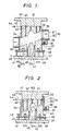
- Fig. 3 shows a sectional view in elevation of the mold of Fig. 1 in fully compressed and closed position with the wood fibers under compression;
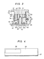
- Fig. 4 shows a plan view of a side plate of the mold used in the first embodiment of the method of the present invention;
- Fig. 5 shows a sectional view in elevation of a mold which can be used in compression molding of wood fibers in accordance with a second embodiment of the method of the invention;
- Fig. 6 shows a view of an apparatus suitable for feeding wood fibers in the first embodiment of the method of the present invention;
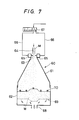
- Fig. 7 is a schematic view showing an apparatus for forming a mass of wood fibers;
- Figs. 8 and 9 are schematic views showing an apparatus for transporting a mass of fibrous material formed by the apparatus of Fig. 7 and an embodiment for the use therof;
- Fig. 10 is a perspective view of a molded wooden product manufactured in accordance with a first embodiment of the method of the present invention;
- Fig. 11 shows a perspective view of a mat of wood fibers used in prior art processes;
- Fig. 12 shows a sectional view in elevation of a prior art mold in which a mat of the type shown in Fig. 11 has been placed; and
- Fig. 13 shows a sectional view in elevation of the mold of Fig. 12 with the mat of Fig. 11 under compression.
- Reference will now be made in detail to the present preferred embodiments of the invention as illustrated in the accompanying drawings. The present invention will be explained in the following examples in which the processes of the present invention are adapted, by way of example, to the molding of a door trim substrate with an arm rest, this product finding utility in the manufacture of automobiles.
- An example of the manufacture of wood fibers will be first explained. Chips comprising small pieces of wood obtained by chipping wood materials are digested and disintegrated at 160°C to 180°C. The wetted wood fibers thus obtained are dried with hot air.
- Next, the dried wood fibers are put into a blender and stirred while they are simultaneously sprayed with 1 to 5% of paraffin as a water repellent agent, 2 to 10% (by dry weight) of phenol resin-aqueous solution (resin content, for example, 50%) as a binder, and a mold lubricant or the like. During the stirring and spraying process, the fibers are well blended while the water content in the wood fibers is appropriately regulated to obtain binder-containing wood fibers.
- The wood fibers to which the binder has been added are directly introduced into a shaping mold, without being formed into a mat. This step is carried out as follows.
- The above-mentioned wood fibers M3 to which the binder has been added are put in a feeding
container 21 of fillingapparatus 20, as shown in Fig. 6. The fillingapparatus 20 is composed of the feedingcontainer 21 and apressure container 22. The two containers are linked with each other via theopening 23 located at the bottom part of the feedingcontainer 21 and the aligned opening 23ʹ at the upper part of the pressure container 2. The alignedopenings 23 and 23ʹ are blocked by the maskingplate 24 which can be opened and shut by the action ofcylinder 26. The maskingplate 24 is reciprocated by the action ofcylinder 26 so that a hole in the masking plate can be brought into and out of alignment with theopenings 23 and 23ʹ. When the maskingplate 24 is opened, i.e., its hole is brought into alignment withholes 23 and 23ʹ, the wood fibers M3 to which the binder and the like have been added fall down to thepressure container 22 through theopenings 23 and 23ʹ. A pair of rotatable brush wheels are provided in the lower part of the feedingcontainer 21 where the wood fibers M3 have been kept. These brushes when rotated cause the top of the brushes to engage with each other which tend to untangle any entangled fibers of the wood fibers M3 that are contacted. - The
pressure container 22 is provided with a weighingplate 27 below the opening 23ʹ, and the wood fibers M3 which fall through this opening pile up on this weighingplate 27. The weight of the wood fibers M3 on the weighingplate 27 is measured by a load cell (not shown) connected to the weighingplate 27, and when the weight has reached predetermined value, the brush wheels are stopped and the maskingplate 24 is shut, thereby terminating the feeding of the wood fibers M3 into thepressure container 22. - With reference to Fig. 1, the
mold 30 comprises anupper mold 31 andlower mold 32. The mold faces are inclined at an angle such that the angle for compression of the portion to be deep-drawn is not too large. Thelower mold 32 comprises several parts including the fixedlower mold part 32a, positioned in the center of the mold for the portion of the fibrous material to be deep-drawn, and the movablelower mold parts 32b which are supported by thesprings 48 and are adjacent to thefixed part 32a. Themold parts 32b are designed to compress the fibrous material surrounding the portion of the fibrous material to be deep-drawn. In the state where theupper mold 31 and thelower mold 32 are open, themovable mold parts 32b positioned adjacent to the deep-drawing part of thelower mold 32 are elevated by thesprings 48 to a height higher than the fixedlower mold part 32a, but thestopper plates 46 connected at the bottom of thelower mold parts 32b act to limit the upward movement of these parts by contact with the top ofstoppers 47. - The
upper mold 31 has a deep-drawing part in concave form. When opened, the shapingmold 30 forms a defined cavity, where the distance across the mold at the deep-drawing part is wider than the other parts of the mold. The periphery of themold 30 is surrounded byside plates mold 30. Theside plates mold 30. Oneside plate 33 has a feeding port 35 (see also Fig. 4) opening to a position corresponding to the opening in the side of the openedmold 30, and theother side plate 34 has a net 36 to hold the wood fibers M3 within the opened mild 30. - The
discharge opening 28 provided in the pressure container 22 (Fig. 6) is designed to be aligned with the feedingport 35 of theside plate 33 of mold 30 (Fig. 1). As air is introduced into thepressure container 22 from the opening opposite to opening 28, the wood fibers M3 accumulated on the weighingplate 27 in thepressure container 22 are transported into themold 30 by the air. In this procedure, the air passes through the net 36 of theouter plate 34, while the wood fibers M3 are contained by the net 36 and thus fill the cavity ofmold 30. - During this introduction of the fibers under pressure, negative or a vacuum is also applied at the downstream side of the net 36. The wood fibers M3 introduced into the
mold 30 under such pressure and vacuum collect from the mold side of the net 36 inwardly without entangling the fibers. In this step, air contained in the wood fibers M3 are degassed by vacuum via the air-removal holes 42 provided in theupper mold 31 and thelower mold 32, and thevacuum ducts 43, to aid in uniformly filling the mold with the wood fibers M3. In the air-removal procedure, the vacuum in the air-removal holes in the side of the lower flow (in upper mold 32) may be varied relative to that of the holes in the side of the upper flow (in upper mold 31) as the filling of the wood fibers M3 in themold 30 progresses. The quantity of wood fibers M3 admitted into themold 30 may be determined on the basis of their weight, as mentioned above, or, alternatively, it may be determined on the basis of the pressure imparted during the introduction of the fibers into the mold while the density of the fibers as they fill the mold is appropriately regulated or monitored. - The wood fibers M3 to which the binder and other additives have been added are now ready to be compression molded. First, the
side plate 33 arranged on the side surface ofmold 30 is moved to cover the mold opening with the use of therack 37 andpinion 39 gearing. Therack 37 is provided below theside plate 33, while thepinion 39 is rotated by themotor 38 fixed to thebracket 40, so that the opening inmold 30 is covered by the part of the side plate 33 (Fig. 4) adjacent to the feedingport 35 thereof, as shown in Fig. 2. In the same manner, theside plate 34 containingnet 36 is also moved by a side-plate sliding means (not shown), so that this opening inmold 30 is covered by the part of theside plate 34 adjacent to the net 36, as also shown in Fig. 2. Thus, the position of theseside plates lower mold 32. - Next, the wood fibers M3 are molded into the desired shape under compression created between the
upper mold 31 and thelower mold 32, which have been heated to a temperature in the range of 150°C to 220°C by thehot plates 41, by downward movement ofupper mold 31 as shown in Fig. 2. The molding surfaces of theparts 32b of thelower mold 32 around the deep-drawingpart 45 are elevated due to thesprings 48, and thus, the wood fibers M3 are sandwiched between the descendingupper mold 31 and thelower mold parts 32b, and pressed together. Thelower mold parts 32b are supported by thesprings 48 and, thus, the force exerted by thesprings 48 is imparted as pressure to the wood fibers M3. However, the height of thesprings 48 is reduced under pressure created byupper mold 31, and thelower mold parts 32b descend as theupper mold 31 descends further. The descent of thelower mold parts 32b stops when thestopper plates 46 provided below these mold parts reach thehot plate 41 at the bottom of the mold. In this state, the wood fibers M3 are closed or compacted in the area around the deep-drawingpart 45, but because a high level of pressure has not yet been imparted, the fibers are not yet formed into a molded product. Any excess of wood fibers resulting from this step flow into the deep-drawing part of the mold so that is is completely filled. - The
upper mold 31 is now lowered further so that the wood fibers M3 across theentire mold 30 are molded into the desired shape by the pressure created by the theupper mold 31 and thelower mold 32 and the applied heat, as shown in Fig. 3. During this step, any gas generated is removed under vacuum by the gas-removal holes 42 via thevacuum ducts 43 and thevalve 44 at the position approximately 10 mm before the bottom dead point of theupper mold 31. The molding parameters can include, for example, a molding pressure of 20 to 80 kg/cm² and a molding time of 20 seconds to 5 minutes. - In this process as just described, the peripheral part of the
mold 30 adjacent to the deep-drawingpart 45 is first partially closed to initially compress the wood fibers in the non-deep-drawn region, thereby preventing further movement of these fibers. Afterwards, the entire mass of fibers is compression molded under heat into the desired shape. This deep-drawn molding process operates in a stable manner without the formation of thin regions in the final product or the susceptibility of the product to breakage or fracture during manufacture. In addition, that part of the product other than the deep-drawn portion is shaped in the initial compressing stage of the molding process, and, therefore, the manufacturing yield is improved by eliminating the waste encountered in the use of the mats. - When the mold is opened, vacuum applied through the gas-removal holes 42 in the
upper mold 31 holds the molded wooden product M4 against theupper mold 31 and it is thus lifted up therewith. After thevalve 44 is closed and vacuum is released, the molded wooden product M4 is removed. The product has the shape of a door trim substrate in which the deep-drawnpart 45 is an arm rest, as shown in Fig. 10. This product is free from defects and has a thickness of 2.5 mm and a bending strength of 200 to 350 kg/cm² or higher. - Since the molding is carried out with the interior mold surfaces being inclined, in the present example, the compression angle and the drawing angle in the deep-drawn portion are small. Therefore, molding can be achieved without the deep-drawn portion being broken, and further, the final product can easily be removed from the mold.
- In this second example of the invention, the wood chips are digested, disintegrated and dried to obtain wood fibers, in the same manner as in Example 1. The wood fibers are preferably blended with the same binder, water-repellant agent, mold lubricant and the like as in Example 1. The wood fibers to which the binder and other additives have been added are put into the compression mold 50 shown in Fig. 5 by use of the same techniques used in describing Example 1.
- The mold 50 comprises an upper mold 51 and a
lower mold 52. The upper mold 51 is divided into a separately movableupper mold part 51a for use in deep-drawing and the adjacent or surroundingupper mold parts 51b. With the wood fibers inside the mold 50, theside plates upper mold part 51a is lowered by the action of therod 49 so that the wood fibers M3 of the portion to be deep-drawn 45 are firmly pressed together in this closing step. Afterwards, theupper mold parts 51b are lowered, and all of the fibers M3 in the mold 50 are molded into the desired shape under hot compression molding by the upper mold 51 and thelower mold 52. The wood fibers in the deep-drawnpart 45 have been pressed together during the closing step and correspond to a pre-shaped mass. Therefore, this portion of the final product is stably deep-drawn without being broken or made made unduly thin. The molding parameters may be the same as used in Example 1. The final product obtained has equally superior strength as that obtained in Example 1. In the process of the present example, additional steps such as pre-compression are unnecessary, and the same or an improved result can be attained as if these steps had been taken. - One embodiment of the mass-forming apparatus for the preparation of the fibrous mass W is shown in Fig. 7. The mass-forming
apparatus 60 is principally comprised of a sprayingcontainer 61 which has an angled roof-like form made of iron plate or the like and alaminating container 62 for laminating the fibrous mixture M comprising wood fibers, binder and other additives.Container 62 is positioned belowcontainer 61. The sprayingcontainer 61 has anopening 63 at the top thereof, and anozzle 64 is provided above opening 63 for spraying the fibrous mixture M fed through a pressure duct (not shown) to the nozzle.Air containers 65 are provided on both sides of opening 63, with each having an orifice in the inside thereof (not shown) for directing a jet of air against the spray. These jets are used for regulating the direction in which the mixture is sprayed. Each of thesecontainers 65 is constructed to receive air fed through air-feedingducts 66 as switched byswitch valve 67. - A
vacuum duct 68 for applying vacuum to the interior of thelaminating container 62 is connected to the bottom side of laminatingcontainer 62. A form-impartingpart 69, which, for example, comprises a metal net, punched metal or the like and which functions to form the bottom surface of the mass into a predetermined shape, is provided above thevacuum duct 68. The laminatingcontainer 62 hasheight sensors 70 on the side wall above the form-impartingpart 69 for detecting the levels and thus the amount of the mixture M and to form the upper surface of the mass W into a desired shape. - The operation of the mass-forming
apparatus 60 is as follows. Theswitch valve 67 is opened to feed air into one or both of theair containers 65 through the air-feedingducts 66, and provide air-flow from the sprayingcontainer 61 to thelaminating container 62. Thereafter, mixture M is released from thenozzle 64 and passes through theopening 63. The released mixture M descends from theopening 63 of the sprayingcontainer 61 along with the air, in a floating manner, into the laminatingcontainer 62 to form a predetermined accumulation on the form-impartingpart 69. In this step, the air jets provided bycontainer 65 are appropriately regulated by switching the switchingvalve 67, or by shutting both the valve and the orifices, so that the direction of the falling mixture M is controlled and the fibers fall on predetermined positions of the form-impartingpart 69 where they quickly accumulate to the desired thickness. In this procedure, air in the mixture is drawn from the bottom of thelaminating container 62 by thevacuum duct 68, and the lamination of the mixture M is accelerated. - As the lamination of the mixture M proceeds, certain of the
height sensors 70 provided on the side wall of thecontainer 62 detect that levels of the mixture M have reached predetermined heights. Theswitch valve 67 is appropriately controlled so that the direction of the fall of the fibrous mixture is changed. Eventually, all thesensors 70 will detect that the desired levels of the mixture M have been attained. At this stage, the feeding of the mixture M is stopped and, at the same time, the feeding of the air from the air-feedingduct 66 is also stopped. The mass of material W having a predetermined shape is thus obtained. The mass W, constituted as a lamination of fibers, has an extremely low density, and, generally, its thickness is selected to be 20 to 120 times that of the final molded product. - In order to transport the fibrous mass W to the mold, the above-described
laminating container 62 is released from the sprayingcontainer 61, and is aligned with a holder 71, for example, as shown in Fig. 8. The holder 71 has a configuration capable of receiving thelaminating container 62, and is provided on the inside with a form-impartingpart 72 comprising a metal net or the like and shaped to correspond to the thickened part WI of the material mass W. The top of holder 71 abovepart 72 is connected with avacuum tube 73. When a vacuum is applied to thevacuum duct 73, the fibrous mass W is elevated by virtue of having a light specific gravity, and closely adheres to the form-impartingpart 72 in the holder 71, and with the vacuum maintained, the holder is also lifted up with the fibrous mass and can now be moved by a conveying means (not shown), in the direction shown in Fig. 9, to a predetermined position within a mold, e.g.,mold 30 or mold 50 of the present invention, where the mass is dropped into the inside of the mold, in contrast to the feeding means used in the mold of Fig. 1, and thereafter the vacuum is released and the mass W is set in the mold. - Additional advantages and modifications will readily occur to those skilled in the art. The invention in its broader aspects is, therefore, not limited to the specific details, representative apparatus and illustrative examples shown and described. Accordingly, departures may be made from such details without departing from the spirit or scope of the applicant's general inventive concept, provided they come within the scope of the appended claims and their equivalents.
Claims (12)
a first step of introducing wood fibers into a compression mold;
a second step of initially compressing the wood fibers other than those wooden fibers used to form the deep-drawn portion to an extent that the compressed fibers are prevented from further movement; and
a third step of compression molding under heat both said wood fibers which were initially compressed under said second step and the wood fibers used to form the deep-drawn portion to produce the molded wooden product.
a first substep of heating the mold to a temperature in the range of 150°C to 220°C; and
a second substep of continuing performance of said third step of compression molding for a time period between 20 seconds and 5 minutes.
a first step introducing the wood fibers into a compression mold;
a second step of initially compressing the wood fibers used to form the deep-drawn portion to an extent that the compressed fibers are prevented from further movement; and
a third step of compression molding under heat both said wood fibers which were initially compressed under said second step and the wood fibers other than the wood fibers used to form the deep-drawn portion to produce the molded wooden product.
a first substep of heating the mold to a temperature in the range of 150°C to 220°C; and
a second substep of continuing performance of said third step of compression molding for a time period between 20 seconds and 5 minutes.
Applications Claiming Priority (4)
| Application Number | Priority Date | Filing Date | Title |
|---|---|---|---|
| JP276612/85 | 1985-12-09 | ||
| JP27661285A JPS62135307A (en) | 1985-12-09 | 1985-12-09 | Manufacture of wooden series molded body |
| JP278194/85 | 1985-12-11 | ||
| JP27819485A JPS62138203A (en) | 1985-12-11 | 1985-12-11 | Manufacture of wooden series molded body |
Publications (3)
| Publication Number | Publication Date |
|---|---|
| EP0225628A2 true EP0225628A2 (en) | 1987-06-16 |
| EP0225628A3 EP0225628A3 (en) | 1989-03-01 |
| EP0225628B1 EP0225628B1 (en) | 1992-07-29 |
Family
ID=26552022
Family Applications (1)
| Application Number | Title | Priority Date | Filing Date |
|---|---|---|---|
| EP19860117067 Expired EP0225628B1 (en) | 1985-12-09 | 1986-12-08 | Method for the manufacture of molded wooden products |
Country Status (4)
| Country | Link |
|---|---|
| EP (1) | EP0225628B1 (en) |
| AU (1) | AU579268B2 (en) |
| CA (1) | CA1291614C (en) |
| DE (1) | DE3686244T2 (en) |
Cited By (10)
| Publication number | Priority date | Publication date | Assignee | Title |
|---|---|---|---|---|
| EP0378757A2 (en) * | 1989-01-20 | 1990-07-25 | Rütgerswerke Aktiengesellschaft | Method and device for the production of shaped articles |
| WO2001081055A1 (en) * | 2000-04-20 | 2001-11-01 | Masonite Corporation | Reverse molded panel |
| US6584743B2 (en) | 2000-04-20 | 2003-07-01 | Masonite Corporation | Decorative skirting (base) board or crown molding |
| US7426806B2 (en) | 2000-04-20 | 2008-09-23 | Masonite Corporation | Reverse molded panel, method of manufacture, and door manufactured therefrom |
| US9284772B2 (en) | 2000-04-20 | 2016-03-15 | Masonite Corporation | Reverse molded plant-on panel component, method of manufacture, and method of decorating a door therewith |
| CN108312574A (en) * | 2018-02-12 | 2018-07-24 | 上海东杰高分子材料有限公司 | A kind of production technology and device of nonwoven 3D moldings composite fibre |
| CN112776118A (en) * | 2021-01-27 | 2021-05-11 | 成都正西液压设备制造有限公司 | Semi-automatic hydraulic press for synthesizing sleeper from bamboo fiber |
| SE2350353A1 (en) * | 2023-03-28 | 2024-09-29 | Pulpac AB | Method for dry-forming cellulose products from cellulose fibres in a product forming unit and a product forming unit |
| SE2350352A1 (en) * | 2023-03-28 | 2024-09-29 | Pulpac AB | A dry-formed three-dimensional cellulose product having a bottle-shaped configuration |
| WO2024199968A1 (en) * | 2023-03-28 | 2024-10-03 | Pulpac AB | Method for dry-forming cellulose products from cellulose fibres in a product forming unit and a product forming unit |
Families Citing this family (1)
| Publication number | Priority date | Publication date | Assignee | Title |
|---|---|---|---|---|
| CN104890097B (en) * | 2015-05-13 | 2017-01-11 | 浙江农林大学 | Wood-bamboo curved plate common mold having multi-plunger oil cylinder and pressing method |
Citations (9)
| Publication number | Priority date | Publication date | Assignee | Title |
|---|---|---|---|---|
| DE1092183B (en) * | 1955-10-05 | 1960-11-03 | G Gassareck Fa | Method and device for pressing pyramidal or truncated cone-shaped hollow bodies closed on one side from a dry, powdery or small-grained molding compound, e.g. If necessary, short wood chips or the like mixed with a binder. |
| FR2144876A1 (en) * | 1971-07-07 | 1973-02-16 | Gkn Sankey Ltd | |
| DE2142003A1 (en) * | 1971-08-21 | 1973-03-01 | Ebers & Mueller Fibrit | Moulding press - with edge turning unit to give a moulded body from fibre material |
| GB2024085A (en) * | 1978-06-29 | 1980-01-09 | Kiss Consulting Eng | A process and apparatus for fabricating preformed objects of cellulose matted non-woven fabrics |
| JPS55164142A (en) * | 1979-06-07 | 1980-12-20 | Eidai Co Ltd | Production of colored particle board |
| DE2945843A1 (en) * | 1979-11-09 | 1981-05-27 | Lignotock Verfahrenstechnik Gmbh, 1000 Berlin | Moulded wood chipboard mfr. - in which male tool pressurises and reverses flexible membrane covering into female air pressurised tool |
| GB2080721A (en) * | 1980-07-24 | 1982-02-10 | Lignotock Verfahrenstech | Producing moulded parts from flat tangled fibre fleece mats |
| DE3045702A1 (en) * | 1980-12-04 | 1982-07-08 | Valentin 6503 Mainz-Kastel Schollmayer | Moulding hollow wood chipboard receptacles - in mould with central spring-loaded retractable plunger in mould cavity base to provide uniform chip distribution |
| DE3419824A1 (en) * | 1984-05-26 | 1985-11-28 | Bayer Ag, 5090 Leverkusen | METHOD AND MOLDING TOOL FOR PRODUCING MOLDED PARTS WITH GRILL, GRID OR RUST-LIKE AREAS, LIKE VEHICLE SOFT FACES, SPOILERS, BUMPER, FROM A FLOWABLE DIMENSION |
Family Cites Families (1)
| Publication number | Priority date | Publication date | Assignee | Title |
|---|---|---|---|---|
| DE2817699A1 (en) * | 1978-04-22 | 1979-10-31 | Hoechst Ag | PROCESS FOR MANUFACTURING STRONG PROFILED MOLDED PARTS |
-
1986
- 1986-12-05 CA CA000524650A patent/CA1291614C/en not_active Expired - Lifetime
- 1986-12-08 DE DE19863686244 patent/DE3686244T2/en not_active Expired - Fee Related
- 1986-12-08 EP EP19860117067 patent/EP0225628B1/en not_active Expired
- 1986-12-08 AU AU66160/86A patent/AU579268B2/en not_active Ceased
Patent Citations (9)
| Publication number | Priority date | Publication date | Assignee | Title |
|---|---|---|---|---|
| DE1092183B (en) * | 1955-10-05 | 1960-11-03 | G Gassareck Fa | Method and device for pressing pyramidal or truncated cone-shaped hollow bodies closed on one side from a dry, powdery or small-grained molding compound, e.g. If necessary, short wood chips or the like mixed with a binder. |
| FR2144876A1 (en) * | 1971-07-07 | 1973-02-16 | Gkn Sankey Ltd | |
| DE2142003A1 (en) * | 1971-08-21 | 1973-03-01 | Ebers & Mueller Fibrit | Moulding press - with edge turning unit to give a moulded body from fibre material |
| GB2024085A (en) * | 1978-06-29 | 1980-01-09 | Kiss Consulting Eng | A process and apparatus for fabricating preformed objects of cellulose matted non-woven fabrics |
| JPS55164142A (en) * | 1979-06-07 | 1980-12-20 | Eidai Co Ltd | Production of colored particle board |
| DE2945843A1 (en) * | 1979-11-09 | 1981-05-27 | Lignotock Verfahrenstechnik Gmbh, 1000 Berlin | Moulded wood chipboard mfr. - in which male tool pressurises and reverses flexible membrane covering into female air pressurised tool |
| GB2080721A (en) * | 1980-07-24 | 1982-02-10 | Lignotock Verfahrenstech | Producing moulded parts from flat tangled fibre fleece mats |
| DE3045702A1 (en) * | 1980-12-04 | 1982-07-08 | Valentin 6503 Mainz-Kastel Schollmayer | Moulding hollow wood chipboard receptacles - in mould with central spring-loaded retractable plunger in mould cavity base to provide uniform chip distribution |
| DE3419824A1 (en) * | 1984-05-26 | 1985-11-28 | Bayer Ag, 5090 Leverkusen | METHOD AND MOLDING TOOL FOR PRODUCING MOLDED PARTS WITH GRILL, GRID OR RUST-LIKE AREAS, LIKE VEHICLE SOFT FACES, SPOILERS, BUMPER, FROM A FLOWABLE DIMENSION |
Non-Patent Citations (1)
| Title |
|---|
| PATENT ABSTRACTS OF JAPAN, vol. 5, no. 39 (M-59)[711], 14th March 1981; & JP-A-55 164 142 (EIDAI SANGYO K.K.) 20-12-1980 * |
Cited By (18)
| Publication number | Priority date | Publication date | Assignee | Title |
|---|---|---|---|---|
| EP0378757A2 (en) * | 1989-01-20 | 1990-07-25 | Rütgerswerke Aktiengesellschaft | Method and device for the production of shaped articles |
| EP0378757A3 (en) * | 1989-01-20 | 1991-11-06 | Rütgerswerke Aktiengesellschaft | Method and device for the production of shaped articles |
| WO2001081055A1 (en) * | 2000-04-20 | 2001-11-01 | Masonite Corporation | Reverse molded panel |
| US6584743B2 (en) | 2000-04-20 | 2003-07-01 | Masonite Corporation | Decorative skirting (base) board or crown molding |
| US6588162B2 (en) | 2000-04-20 | 2003-07-08 | Masonite Corporation | Reverse molded panel |
| US7426806B2 (en) | 2000-04-20 | 2008-09-23 | Masonite Corporation | Reverse molded panel, method of manufacture, and door manufactured therefrom |
| US7730686B2 (en) | 2000-04-20 | 2010-06-08 | Masonite Corporation | Reverse molded panel |
| US8820017B2 (en) | 2000-04-20 | 2014-09-02 | Masonite Corporation | Reverse molded panel |
| US9284772B2 (en) | 2000-04-20 | 2016-03-15 | Masonite Corporation | Reverse molded plant-on panel component, method of manufacture, and method of decorating a door therewith |
| US9657512B2 (en) | 2000-04-20 | 2017-05-23 | Masonite Corporation | Reverse molded plant-on panel component, method of manufacture, and method of decorating a door therewith |
| CN108312574A (en) * | 2018-02-12 | 2018-07-24 | 上海东杰高分子材料有限公司 | A kind of production technology and device of nonwoven 3D moldings composite fibre |
| CN112776118A (en) * | 2021-01-27 | 2021-05-11 | 成都正西液压设备制造有限公司 | Semi-automatic hydraulic press for synthesizing sleeper from bamboo fiber |
| CN112776118B (en) * | 2021-01-27 | 2024-02-09 | 成都正西液压设备制造有限公司 | Semi-automatic hydraulic press for bamboo fiber synthesized sleeper |
| SE2350353A1 (en) * | 2023-03-28 | 2024-09-29 | Pulpac AB | Method for dry-forming cellulose products from cellulose fibres in a product forming unit and a product forming unit |
| SE2350352A1 (en) * | 2023-03-28 | 2024-09-29 | Pulpac AB | A dry-formed three-dimensional cellulose product having a bottle-shaped configuration |
| WO2024199989A1 (en) * | 2023-03-28 | 2024-10-03 | Pulpac AB | Method for dry-forming cellulose products from cellulose fibres in a product forming unit and a product forming unit |
| WO2024199966A1 (en) * | 2023-03-28 | 2024-10-03 | Pulpac AB | Method for dry-forming cellulose products from cellulose fibres in a product forming unit and a product forming unit |
| WO2024199968A1 (en) * | 2023-03-28 | 2024-10-03 | Pulpac AB | Method for dry-forming cellulose products from cellulose fibres in a product forming unit and a product forming unit |
Also Published As
| Publication number | Publication date |
|---|---|
| EP0225628A3 (en) | 1989-03-01 |
| EP0225628B1 (en) | 1992-07-29 |
| AU6616086A (en) | 1987-06-11 |
| DE3686244D1 (en) | 1992-09-03 |
| CA1291614C (en) | 1991-11-05 |
| AU579268B2 (en) | 1988-11-17 |
| DE3686244T2 (en) | 1993-01-07 |
Similar Documents
| Publication | Publication Date | Title |
|---|---|---|
| CA1294408C (en) | Molded wooden products | |
| US4960548A (en) | Method of manufacturing molded wooden product | |
| EP0225628B1 (en) | Method for the manufacture of molded wooden products | |
| EP0226163A2 (en) | Process for producing molded wooden products having a hole therein | |
| JPH0620732B2 (en) | Method for manufacturing wood-based molded body | |
| EP0226170A2 (en) | Process for producing molded wooden products without gas retention | |
| CA1171742A (en) | Self-supporting moldable fiber mat and process for producing the same | |
| JPH01283106A (en) | Manufacturing device for ligneous molded product | |
| JPS62135307A (en) | Manufacture of wooden series molded body | |
| JPS62119003A (en) | Preparation of wooden molding | |
| JPH0712604B2 (en) | Method for manufacturing wood-based molded body | |
| JPH0679810B2 (en) | Method for manufacturing wood-based molded body | |
| CA1144326A (en) | Articles molded from papermill sludge | |
| JPH0641125B2 (en) | Method for manufacturing wood-based molded body | |
| JPS62135306A (en) | Manufacture of wooden series molded body | |
| JPS62135317A (en) | Manufacture of wooden series molded body | |
| JPH07292B2 (en) | Method for manufacturing wood-based molded body | |
| Haataja et al. | Articles molded from papermill sludge | |
| JPH0645126B2 (en) | Equipment for manufacturing wood-based compacts | |
| JPS62135313A (en) | Manufacture of wooden series molded body | |
| JPH01285304A (en) | Manufacturing device for ligneous molding | |
| JPH0679808B2 (en) | Method for manufacturing wood-based molded body | |
| JPS62135303A (en) | Manufacture of wooden series molded body | |
| JPS62135304A (en) | Manufacture of wooden series molded body | |
| JPS62135312A (en) | Manufacture of wooden series molded body |
Legal Events
| Date | Code | Title | Description |
|---|---|---|---|
| PUAI | Public reference made under article 153(3) epc to a published international application that has entered the european phase |
Free format text: ORIGINAL CODE: 0009012 |
|
| AK | Designated contracting states |
Kind code of ref document: A2 Designated state(s): DE FR GB SE |
|
| PUAL | Search report despatched |
Free format text: ORIGINAL CODE: 0009013 |
|
| RHK1 | Main classification (correction) |
Ipc: B27N 5/00 |
|
| AK | Designated contracting states |
Kind code of ref document: A3 Designated state(s): DE FR GB SE |
|
| 17P | Request for examination filed |
Effective date: 19890804 |
|
| 17Q | First examination report despatched |
Effective date: 19901204 |
|
| GRAA | (expected) grant |
Free format text: ORIGINAL CODE: 0009210 |
|
| AK | Designated contracting states |
Kind code of ref document: B1 Designated state(s): DE FR GB SE |
|
| ET | Fr: translation filed | ||
| REF | Corresponds to: |
Ref document number: 3686244 Country of ref document: DE Date of ref document: 19920903 |
|
| PLBE | No opposition filed within time limit |
Free format text: ORIGINAL CODE: 0009261 |
|
| STAA | Information on the status of an ep patent application or granted ep patent |
Free format text: STATUS: NO OPPOSITION FILED WITHIN TIME LIMIT |
|
| 26N | No opposition filed | ||
| REG | Reference to a national code |
Ref country code: FR Ref legal event code: ST |
|
| REG | Reference to a national code |
Ref country code: FR Ref legal event code: R1 |
|
| REG | Reference to a national code |
Ref country code: FR Ref legal event code: DS |
|
| PGFP | Annual fee paid to national office [announced via postgrant information from national office to epo] |
Ref country code: GB Payment date: 19941129 Year of fee payment: 9 |
|
| PGFP | Annual fee paid to national office [announced via postgrant information from national office to epo] |
Ref country code: DE Payment date: 19941208 Year of fee payment: 9 |
|
| PGFP | Annual fee paid to national office [announced via postgrant information from national office to epo] |
Ref country code: FR Payment date: 19941209 Year of fee payment: 9 |
|
| PGFP | Annual fee paid to national office [announced via postgrant information from national office to epo] |
Ref country code: SE Payment date: 19941215 Year of fee payment: 9 |
|
| EAL | Se: european patent in force in sweden |
Ref document number: 86117067.8 |
|
| PG25 | Lapsed in a contracting state [announced via postgrant information from national office to epo] |
Ref country code: GB Effective date: 19951208 |
|
| PG25 | Lapsed in a contracting state [announced via postgrant information from national office to epo] |
Ref country code: SE Effective date: 19951209 |
|
| GBPC | Gb: european patent ceased through non-payment of renewal fee |
Effective date: 19951208 |
|
| PG25 | Lapsed in a contracting state [announced via postgrant information from national office to epo] |
Ref country code: FR Effective date: 19960830 |
|
| PG25 | Lapsed in a contracting state [announced via postgrant information from national office to epo] |
Ref country code: DE Effective date: 19960903 |
|
| REG | Reference to a national code |
Ref country code: FR Ref legal event code: ST |