EP0225513A2 - Verfahren und Vorrichtung zur Herstellung von Zahnersatz - Google Patents
Verfahren und Vorrichtung zur Herstellung von Zahnersatz Download PDFInfo
- Publication number
- EP0225513A2 EP0225513A2 EP86115979A EP86115979A EP0225513A2 EP 0225513 A2 EP0225513 A2 EP 0225513A2 EP 86115979 A EP86115979 A EP 86115979A EP 86115979 A EP86115979 A EP 86115979A EP 0225513 A2 EP0225513 A2 EP 0225513A2
- Authority
- EP
- European Patent Office
- Prior art keywords
- electrodes
- formula
- negative
- tooth replacement
- replacement part
- Prior art date
- Legal status (The legal status is an assumption and is not a legal conclusion. Google has not performed a legal analysis and makes no representation as to the accuracy of the status listed.)
- Granted
Links
- 238000000034 method Methods 0.000 title claims abstract description 27
- 238000004519 manufacturing process Methods 0.000 claims abstract description 15
- 239000011343 solid material Substances 0.000 claims abstract description 13
- 230000003628 erosive effect Effects 0.000 claims abstract description 11
- 238000009760 electrical discharge machining Methods 0.000 claims abstract description 9
- 239000000463 material Substances 0.000 claims description 16
- 239000004020 conductor Substances 0.000 claims description 4
- 239000002184 metal Substances 0.000 description 10
- 229910052751 metal Inorganic materials 0.000 description 10
- 238000005266 casting Methods 0.000 description 9
- 239000011505 plaster Substances 0.000 description 4
- 150000002739 metals Chemical class 0.000 description 3
- 150000001875 compounds Chemical class 0.000 description 2
- 238000001816 cooling Methods 0.000 description 2
- OKTJSMMVPCPJKN-UHFFFAOYSA-N Carbon Chemical compound [C] OKTJSMMVPCPJKN-UHFFFAOYSA-N 0.000 description 1
- BQCADISMDOOEFD-UHFFFAOYSA-N Silver Chemical compound [Ag] BQCADISMDOOEFD-UHFFFAOYSA-N 0.000 description 1
- 238000004026 adhesive bonding Methods 0.000 description 1
- 230000015572 biosynthetic process Effects 0.000 description 1
- 238000005260 corrosion Methods 0.000 description 1
- 230000007797 corrosion Effects 0.000 description 1
- 238000005553 drilling Methods 0.000 description 1
- 238000004070 electrodeposition Methods 0.000 description 1
- 238000005516 engineering process Methods 0.000 description 1
- PCHJSUWPFVWCPO-UHFFFAOYSA-N gold Chemical compound [Au] PCHJSUWPFVWCPO-UHFFFAOYSA-N 0.000 description 1
- 239000010931 gold Substances 0.000 description 1
- 229910052737 gold Inorganic materials 0.000 description 1
- 239000010439 graphite Substances 0.000 description 1
- 229910002804 graphite Inorganic materials 0.000 description 1
- 239000010440 gypsum Substances 0.000 description 1
- 229910052602 gypsum Inorganic materials 0.000 description 1
- 239000007788 liquid Substances 0.000 description 1
- 238000003754 machining Methods 0.000 description 1
- 238000002844 melting Methods 0.000 description 1
- 230000008018 melting Effects 0.000 description 1
- 238000000465 moulding Methods 0.000 description 1
- 239000011148 porous material Substances 0.000 description 1
Images
Classifications
-
- A—HUMAN NECESSITIES
- A61—MEDICAL OR VETERINARY SCIENCE; HYGIENE
- A61C—DENTISTRY; APPARATUS OR METHODS FOR ORAL OR DENTAL HYGIENE
- A61C13/00—Dental prostheses; Making same
- A61C13/0003—Making bridge-work, inlays, implants or the like
- A61C13/0006—Production methods
- A61C13/0015—Production methods using electrical discharge machining [EDM], e.g. spark erosion
-
- A—HUMAN NECESSITIES
- A61—MEDICAL OR VETERINARY SCIENCE; HYGIENE
- A61C—DENTISTRY; APPARATUS OR METHODS FOR ORAL OR DENTAL HYGIENE
- A61C13/00—Dental prostheses; Making same
- A61C13/0003—Making bridge-work, inlays, implants or the like
-
- B—PERFORMING OPERATIONS; TRANSPORTING
- B23—MACHINE TOOLS; METAL-WORKING NOT OTHERWISE PROVIDED FOR
- B23H—WORKING OF METAL BY THE ACTION OF A HIGH CONCENTRATION OF ELECTRIC CURRENT ON A WORKPIECE USING AN ELECTRODE WHICH TAKES THE PLACE OF A TOOL; SUCH WORKING COMBINED WITH OTHER FORMS OF WORKING OF METAL
- B23H9/00—Machining specially adapted for treating particular metal objects or for obtaining special effects or results on metal objects
Definitions
- the invention relates to a method and a device for producing dental prosthesis parts by means of the spark erosion method with the features of the type described in the preamble of claim 1.
- a method for the production of dental prosthetic items has also become known, in which the electrically conductive and coated plaster model stump, which corresponds to the tooth stump shaped by the dentist, is used as an electrode for spark-erosive reworking of the fit of the dental prosthesis produced by casting becomes.
- Five negative-positive transfers are required to fabricate a cementable cast model of the denture.
- the first impression step is the creation of the negative impression form of the natural tooth stump.
- a positive plaster model is made from this impression mold.
- the positive plaster model is supplemented by a wax model from the dental technician.
- the positive wax model is embedded in a mold in a casting compound and melted out. Metal is poured into the casting mold thus created and thus the metal model of the denture is produced.
- Each of these molding steps is associated with procedural errors, which are expressed in part in positive, in part also in negative dimensional changes.
- These dimensional changes arise, for example, from changes in the volume of the impression compound caused by polymerisation during the production of the negative impression form. Gypsum expansion may occur during the manufacture of the plaster model.
- the processing errors of the wax result from the wax properties and the processing temperature of the wax. Cooling the wax and setting processes on the investment material can also lead to errors.
- the processing temperature of the liquid cast metal and its dimensional change during cooling also impair the precise manufacture of a metal model, pores and voids are formed, for example, and there are structural changes that lead to corrosion.
- the invention is therefore based on the object of producing dental prostheses in a technically simple and cost-effective manner, furthermore making it possible to manufacture them without any rework with regard to the fit and without the material problems arising during casting, and thus to be able to use new and better materials which cannot be processed using casting technology.
- the advantages of the invention are in particular that a casting process is avoided in the manufacture of the dental prosthetic item.
- the spark erosive working out of the dental prosthetic item directly from the full material eliminates any fitting errors between the dental prosthetic item and the prepared one Avoid tooth stump. If one uses the same electrically conductive material for the creation of the negative impression form of the tooth and does so when creating the model of the tooth replacement part, then the negative forms of the formula electrodes for the erosive process can be created directly from these electrically conductive parts.
- inexpensive metals which, for example, are work hardened. These materials sometimes have better properties than gold in their function as dentures.
- the solid material is the material from which the dentures to be used are to be made. This can be, for example, work hardened metals such as Inconell or any other suitable tooth replacement Material.
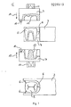
- the dental prosthetic item 5 is connected by means of two form electrodes 2 and 7, which are also referred to as the upper and lower form electrodes. These electrodes are connected to a spark erosion device, which is not shown for the sake of clarity and is constructed in accordance with the prior art.
- the two formula electrodes 2 and 7 are designed as upper and lower half-shells and each have negative shapes 12 and 13 on their inside, which have an electrically conductive surface and are modeled on the model of the dental prosthetic item or the impression of the tooth stump in the patient's jaw.
- the formula electrodes 2 and 7 have position elements 11 for holding the two electrodes and also a position element 10 which ensures the exact fit of the two formula electrodes to one another.
- the negative molds 12 and 13 of the formula electrodes 2 and 7 for the tooth replacement part 5 can also be erosively produced directly from a previously unprocessed solid material.
- the negative forms 12 and 13 of the formula electrodes can be obtained by two different methods.
- the upper formula electrode 2 can be obtained from a model of the tooth replacement part 5, in which the material for producing the model is electrically conductive from the outset.
- the lower formula electrode 7 can be produced from a negative impression of the tooth stump, the material for producing the negative impression from the outset consisting of electrically conductive material.
- the formula electrodes initially consist of a non-electrically conductive base material, the surface of which is subsequently made electrically conductive for the negative forms 12 and 13, for example by application of colloidal silver on the non-conductive base material and subsequent electrodeposition of a metal layer.
- the impression material for the formula electrodes which are manufactured from the outset from electrically conductive material, is e.g. Metal, conductive plastic or graphite in question.
- the shapes of the upper and lower formula electrodes 2 and 7 are designed such that 3 thin connecting webs are preserved during the eroding process between the resulting denture part 5 and the remaining solid material. These connecting webs 6 serve to fix the dental prosthetic item 5 during the machining process and are created by the special design of the electrodes 2 and 7. After the eroding process, the webs 6 are broken out, the break points of the webs are smoothed, these webs being arranged from the outset at uncritical points in the dental prosthesis have been.
- the method for producing the dental prosthetic item 5 from the solid material 3 according to FIG. 1 works as follows.
- the two formula electrodes 2 and 7 with their negative shapes 12 and 13 face each other on the solid material 3 simultaneously closed otherwise, as the two arrows 14 and 15 indicate.
- the denture part 5 is thus created by simultaneously moving the formula electrodes 2 and 7 together.
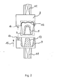
- FIG. 2 Another method for obtaining the dental prosthesis is described in FIG. 2.
- An upper and a lower formula electrodes 8 and 9 are also shown there, which are identical to the previously described formula electrodes 2 and 7 from the exemplary embodiment according to FIG. The same parts are provided with the same reference numerals and it will not be explained again.
- This second method for obtaining the dental prosthetic item 5 works as follows. From the solid material 4, which can for example be a metal block, only the first half of the tooth replacement part 5 is erosively worked out with the upper formula electrode 8, the crown part of the tooth being worked out here as the first half. Of course, this order can also be reversed and you can start working out the lower part of the denture part.
- the half of the tooth replacement part 5 which has already been preformed is connected to the negative form 12 of the formula electrode 8, for example by gluing.
- the not yet finished dental prosthetic item 5 is firmly fixed in the formula electrode 8.
- the second half of the tooth replacement part 5 is eroded with the lower formula electrode 9, in that the formula electrode 9 is moved in the direction of the arrow 16 onto the upper formula electrode 8 and thus the tooth replacement part 5.
- the dental prosthetic item 5 is detached from the negative shape of the upper electrode 8.
- the dental prosthetic item 5 is now finished; no rework is required for a precisely fitting seat.
Landscapes
- Health & Medical Sciences (AREA)
- General Health & Medical Sciences (AREA)
- Engineering & Computer Science (AREA)
- Oral & Maxillofacial Surgery (AREA)
- Dentistry (AREA)
- Epidemiology (AREA)
- Life Sciences & Earth Sciences (AREA)
- Public Health (AREA)
- Veterinary Medicine (AREA)
- Animal Behavior & Ethology (AREA)
- Physics & Mathematics (AREA)
- Manufacturing & Machinery (AREA)
- Thermal Sciences (AREA)
- Mechanical Engineering (AREA)
- Dental Prosthetics (AREA)
- Dental Preparations (AREA)
Abstract
Description
- Die Erfindung betrifft ein Verfahren und eine Vorrichtung zur Herstellung von Zahnersatzteilen mittels des Funkenerosionsverfahrens mit den Merkmalen der im Oberbegriff des Patentanspruchs 1 beschriebenen Gattung.
- Derartige Verfahren und Vorrichtungen sind an sich bekannt. Aus der DE-05 31 18 890 ist ein Verfahren zur Herstellung von Zahnersatzteilen bekannt, bei dem ein metallisches Sekundärteil abnehmbar über Halteelemente an einem ebenfalls metallischen festsitzenden Primärteil verankert ist. Als Halteelemente dienen Riegel oder Friktionsstifte, für die entsprechende Aufnahmen mit genauer Passung im Pri- .mär- und im Sekundärteil geschaffen werden. Dazu wird eine Erosionsmaschine eingesetzt, mit der die Lager für den Riegel im Primärteil wie auch im Sekundärteil gemeinsam durch Funkenerosion hergestellt werden. Die Erosionsmaschine wird dabei lediglich als ein Bohrwerkzeug für die Herstellung der Lager der Riegel benutzt. Wie dagegen das Primärteil an den Zahnstumpf oder das Sekundärteil an das Primärteil hinsichtlich der Kontaktfläche angepaßt werden bleibt völlig offen.
- Aus der DE-OS 33 20 902 ist ferner ein Verfahren zur Herstellung von Zahnersatzteilen bekannt geworden, bei dem der elektrisch leitfähig gemachte und überzogene Gipsmodellstumpf, der dem vom Zahnarzt geformten Zahnstumpf entspricht, als Elektrode zur funkenerosiven Nacharbeit des Paßsitzes des durch Gießen hergestellten Zahnersatzes herangezogen wird. Bis zum Herstellen eines zementierbaren durch Gießen hergestellten Modellsdes Zahnersatzes sind fünf Negativ-Positiv-Übertragungen erforderlich. Der erste Abformschritt ist die Erstellung der negativen Abdruckform des -natürlichen Zahnstumpfes. Von dieser Abdruckform wird ein positives Gipsmodell hergestellt. Das positive Gipsmodell wird durch ein Wachsmodell des Zahntechnikers ergänzt. Das positive Wachsmodell wird in eine Form in eine Abgußmasse eingebettet und ausgeschmolzen. In die so geschaffene Gußform wird Metall eingegossen und so das Metallmodell des Zahnersatzes hergestellt. Jeder dieser Abformschritte ist mit verfahrensbedingten Fehlern behaftet, die sich teilweise in positiven, teilweise auch in negativen Dimensionsänderungen äußern. Diese Dimensionsänderungen entstehen beispielsweise durch polimerisationsbedingte Volumenänderungen der Abdruckmasse bei der Herstellung der negativen Abdruckform. Bei der Herstellung des Gipsmodelles-kann eine Gipsexpansion auftreten. Die Verarbeitungsfehler des Waches resultieren aus den Wachseigenschaften und der Verarbeitungstemperatur des Wachses. Auch die Abkühlung des Wachses und Abbindevorgänge an der Einbettmasse können zu Fehlern führen. Auch die Verarbeitungstemperatur des flüssig engegossenen Metalls und dessen Dimensionsänderung bei der Abkühlung beeinträchtigen die genaue Herstellung eines Metallmodells, es bilden sich beispielsweise Poren und Lunker, ferner stellen sich Gefügeänderungen ein, die zur Korrosion führen. Mit jeder Abformung addieren sich die verfahrensbedingten Fehler, was zu erheblichen Dimensionsänderungen führt, die nicht mehr toleriert werden können und zu erheblichen Nacharbeit für den Paßsitz des Zahnersatzteils führen, wobei die Kosten für diese Nacharbeit bis zur Hälfte der Kosten des gesamten Zahnersatzes betragen kann. Als weiterer erheblicher Nachteil des auf dem gießtechnischen Wege hergestellten Zahnersatzteiles besteht darin, daß- nur gießfähigeMaterialien verwendet werden können oder gießfähige Materialien wegen zu hoher Schmelztemperatur nicht eingesetzt werden konnten. So konnten beispielsweise kaltverfestigte Metalle nicht eingesetzt werden, die wesentlich kostengünstiger sind und von vornherein eine Lunkerbildung und eine Gefügeänderung ausschließen.
- Der Erfindung liegt deshalb die Aufgabe zugrunde, Zahnersatz technisch einfach und kostengünstig herzustellen, ferner eine Herstellung ohne jede Nacharbeit bezüglich der Paßform und ohne die beim Gießen entstehenden Materialprobleme zu ermöglichen und damit neue und bessere Materialien verwenden zu können, die gießtechnisch nicht verarbeitet werden können.
- Die Vorteile der Erfindung bestehen insbesondere darin, daß ein Gießvorgang bei der Herstellung des Zahnersatzteiles vermieden wird. Durch das funkenerosive Herausarbeiten des Zahnersatzteiles direkt aus dem vollen Material werden jegliche Paßfehler zwischen dem Zahnersatzteil und dem präparierten Zahnstumpf vermieden. Verwendet man für die Erstellung der negativen Abdruckform des Zahnes gleich elektrisch leitfähiges Material und tut dies auch bei der Erstellung des Modells des Zahnersatzteils, so können direkt von diesen elektrisch leitfähigen Teilen die negativen Formen der Formelektroden für das erosive Verfahren erstellt werden. Durch den Wegfall des Gießvorgangs bei der Herstellung des Zahnersatzteils können außerdem kostengünstige Metalle Verwendung finden, die beispielsweise kalt verfestigt sind. Diese Materialien besitzen teilweise bessere Eigenschaften als Gold in ihrer Funktion als Zahnersatz.
- Nachstehend wird die Erfindung anhand von Ausfüh- rungsbeispielen von Zeichnen noch näher erläutert.
- Es zeigen:
- Figur 1 eine erste Ausführungsform des Verfahrens und der Vorrichtung zur Herstellung von Zahnersatzteilen auf dem funkenerosiven Weg und
- Figur 2 ein zweites Verfahren zur Herstellung des Zahnersatzes-ohne Guß auf funkenerosivem Weg.
- Aus Figur 1 ist eine Vorrichtung zur Herstellung von Zahnersatz aus Vollmaterial 3 ersichtlich. Das Vollmaterial ist dasjenige Material, aus dem der einzusetzende Zahnersatz hergestellt werden soll. Das können z.B. kalt verfestigte Metalle wie Inconelloder auch jeder andere für einen Zahnersatz geeignete Werkstoff sein. Das Zahnersatzteil 5 wird mittels zweier Formelektroden 2 und 7, die auch als obere und gewonnen untere Formeleektrode bezeichnet werNen,VDiese Elektroden sind an ein Funkenerosionsgerät angeschlossen, das der Übersichtlichkeit halber nicht näher dargestellt ist und entsprechend dem Stand der Technik aufgebaut ist. Die beiden Formelektroden 2 und 7 sind als obere und unter Halbschale ausgebildet und besitzen auf ihrer Innenseite jeweils negative Formen 12 und 13, die eine elektrisch leitende Oberfläche haben und dem Modell des Zahnersatzteils bzw. dem Abdruck des -Zahnstumpfes im Kiefer des Patienten nachgebildet sind. Die Formelektroden 2 und 7 besitzen Positionselemente 11 zum Halten der beiden Elektroden und ferner ein Positionselement 10 das die genaue Paßform der beiden Formelektroden zueinander sicherstellt.
- Die Negativ-Formen 12 und 13 der Formelektroden 2 und 7 für das Zahnersatzteil 5 können dabei ebenfalls auf erosivem Wege direkt aus einem vorher nicht bearbeiteten Vollmaterial hergestellt werden. Die negativen Formen 12 und 13 der Formelektroden können dabei durch zwei verschiedene Methoden gewonnen werden. Es kann einerseits die obere Formelektrode 2 aus einem Modell des Zahnersatzteiles 5 gewonnen werden, bei dem das Material zur Herstellung des Modells von vornherein elektrisch leitfähig ist. Andererseits kann die untere Formelektrode 7 aus einer negativen Abformung des Zahnstumpfes hergestellt werden, wobei das Material zur Herstellung der negativen Abformung von vornherein aus elektrisch leitfähigem Material besteht.
- Eine andere Methode zur Gewinnung der negativen Formen 12 und 13 der Formelektroden 2 und 7 besteht darin, daß die Formelektroden zunächst aus einem nicht elektrisch leitfähigen Grundmaterial bestehen, dessen Oberfläche nachträglich für die negativen Formen 12 und 13 elektrisch leitfähig gemacht werden, was beispeilsweise durch Aufbringen von kolloidalem Silber auf dem nichtleitfähigen Grundmaterial und anschließendem elektrolytischen Abscheiden einer Metallschicht geschehen kann.
- Als Abformmaterial für die Formelektroden, die von vornherein aus elektrisch leitfähigem Material hergestellt werden,kommt z.B. Metall, Leitplastik oder Graphit in Frage.
- Aus Figur 1 ist ferner ersichtlich, daß die Formen der oberen und unteren Formelektrode 2 und 7 derart ausgebildet sind, daß beim Erodiervorgang zwischen dem entstehenden Zahnersatzteil 5 und dem restlichen Vollmaterial 3 dünne Verbindungsstege erhalten bleiben. Diese Verbindungsstege 6 dienen der Fixierung des Zahnersatzteils 5 während des Bearbeitungsvorgangs und entstehen durch die besondere Gestaltung der Elektroden 2 und 7. Nach dem Erodiervorgang werden die Stege 6 herausgebrochen, die Bruchstellen der Stege geglättet, wobei diese Stege von vornherein an unkritischen Stellen des Zahnersatzes angeordnet worden sind.
- Das Verfahren zur Herstellung des Zahnersatzteils 5 aus dem Vollmaterial 3 gemäß Figur 1 arbeitet dabei folgendermaßen. Es werden die beiden Formelektroden 2 und 7 mit ihren negativen Formen 12 und 13 einander zugekehrt auf das Vollmaterial 3 gleichzeitig aufeinander zugefahren, wie die beiden Pfeile 14 und 15 dies andeuten. Damit entsteht das Zahnersatzteil 5 durch gleichzeitiges Aufeinanderzufahren der Formelektroden 2 und 7.
- Ein anderes Verfahren zur Gewinnung des Zahnersatzes ist in Figur 2 beschrieben. Dort sind ebenfalls eine obere und eine untere Formelektrode 8 und 9 dargestellt, die identisch mit den bereits beschriebenen Formelektroden 2 und 7 aus dem Ausführungsbeispiel nach Figur 1 ausgebildet sind. Gleiche Teile sind mit gleichen Bezugszeichen versehen und es wird davon abgesehen, diese nochmals zu erläutern. Dieses zweite Verfahren zur Gewinnung des Zahnersatzteils 5 arbeitet wie folgt. Aus dem Vollmaterial 4, das beispielsweise ein Metallklotz sein kann, wird mit der oberen Formelektrode 8 zunächst nur die erste Hälfte des Zahnersatzteils 5 erosiv herausgearbeitet, als erste Hälfte ist hier der Kronenteil des Zahnes herausgearbeitet. Selbstverständlich kann diese Reihenfolge auch umgekehrt sein und es kann zunächst mit dem Herausarbeiten des Unterteils des Zahnersatzteils begonnen werden. Nachdem nun die erste Hälfte des Zahnersatzteils herausgearbeitet ist, wird diepereits vorgeformte Hälfte des Zahnersatzteils 5 beispielsweise durch Kleben mit der negativen Form 12 der Formelektrode 8 verbunden. Dadurch ist das noch nicht fertige entstehende Zahnersatzteil 5 in der Formelektrode 8 fest fixiert. Jetzt erst wird mit der unteren Formelektrode 9 die zweite Hälfte des Zahnersatzteiles 5 erodiert, indem die Formelektrode 9 in Richtung des Pfeiles 16 auf die obere Formelektrode 8 und damit das Zahnersatzteil 5 zugefahren wird. Nach Fertigstellung des Zahnersatzteils 5, das bei dieser Herstellungsmethode keine Verbindungsstege besitzt, wird das Zahnersatzteil 5 aus der negativen Form der oberen Elektrode 8 herausgelöst. Das Zahnersatzteil 5 ist damit fertig, es bedarf zu einem passgenauen Sitz keinerlei Nacharbeit.
Claims (8)
dadurch gekennzeichnet, daß mit Hilfe von zwei Formelektroden (2,7,8,9) das einzusetzende Zahnersatzteil (5) mittels des Funkenerosionsverfahrens direkt aus dem vorher nicht bearbeiteten Vollmaterial hergestellt wird.
Priority Applications (1)
| Application Number | Priority Date | Filing Date | Title |
|---|---|---|---|
| AT86115979T ATE65376T1 (de) | 1985-12-13 | 1986-11-18 | Verfahren und vorrichtung zur herstellung von zahnersatz. |
Applications Claiming Priority (2)
| Application Number | Priority Date | Filing Date | Title |
|---|---|---|---|
| DE3544123 | 1985-12-13 | ||
| DE19853544123 DE3544123A1 (de) | 1985-12-13 | 1985-12-13 | Verfahren und vorrichtung zur herstellung von zahnersatz |
Publications (3)
| Publication Number | Publication Date |
|---|---|
| EP0225513A2 true EP0225513A2 (de) | 1987-06-16 |
| EP0225513A3 EP0225513A3 (en) | 1988-10-19 |
| EP0225513B1 EP0225513B1 (de) | 1991-07-24 |
Family
ID=6288377
Family Applications (1)
| Application Number | Title | Priority Date | Filing Date |
|---|---|---|---|
| EP86115979A Expired - Lifetime EP0225513B1 (de) | 1985-12-13 | 1986-11-18 | Verfahren und Vorrichtung zur Herstellung von Zahnersatz |
Country Status (6)
| Country | Link |
|---|---|
| US (1) | US4734173A (de) |
| EP (1) | EP0225513B1 (de) |
| JP (1) | JPS62243553A (de) |
| AT (1) | ATE65376T1 (de) |
| DE (1) | DE3544123A1 (de) |
| ES (1) | ES2040696T3 (de) |
Cited By (7)
| Publication number | Priority date | Publication date | Assignee | Title |
|---|---|---|---|---|
| JPS6411539A (en) * | 1987-07-03 | 1989-01-17 | Tomo Shimizu | Artificial dental root |
| EP0312699A2 (de) | 1987-10-21 | 1989-04-26 | Heraeus Kulzer GmbH | Verfahren zur Herstellung von Dental-Ersatzteilen, wie Kronen- oder Brücken, mittels Funkenerosion |
| WO1991006256A1 (de) * | 1989-10-24 | 1991-05-16 | Krupp Medizintechnik Gmbh | Verfahren zur herstellung von zahnersatzteilen mittels funkenerosion und vorrichtung zum einspannen, einlegen und ausrichten von gipsmodellen oder kupferelektroden für die funkenerosive herstellung von zahnersatzteilen |
| WO1993010720A1 (de) * | 1991-11-26 | 1993-06-10 | Krupp Medizintechnik Gmbh | Verfahren zur herstellung von zahnersatzteilen |
| EP0666062A1 (de) * | 1994-01-28 | 1995-08-09 | Günter Rübeling | Verfahren und Vorrichtung zur Herstellung von an Implantaten zu befestigenden zahnprothetischen Gerüsten |
| EP0722698A3 (de) * | 1995-01-20 | 1996-12-27 | Thera Ges Fuer Patente | Verfahren und Vorrichtung zur sonoerosiven Herstellung eines individuellen Formteils |
| CN114260526A (zh) * | 2021-12-22 | 2022-04-01 | 东莞市爱嘉义齿有限公司 | 3d打印金属义齿的线切割装置 |
Families Citing this family (18)
| Publication number | Priority date | Publication date | Assignee | Title |
|---|---|---|---|---|
| DE3911362A1 (de) * | 1989-04-07 | 1990-10-11 | Herbert Walter | Vorrichtung zur funkenerosionsbearbeitung mehrerer rohlinge |
| DE3928684A1 (de) * | 1989-08-30 | 1991-04-04 | Hahn Rainer | Sonotrode |
| US5290988A (en) * | 1991-02-22 | 1994-03-01 | Precision Pattern, Template & Shoe, Inc. | Method for machining a precision conformed hold-down pressure shoe |
| DE4332065C2 (de) * | 1992-09-24 | 1998-07-09 | Thera Ges Fuer Patente | Ultraschallbearbeitungsvorrichtung und Verfahren zur Bearbeitung von Werkstücken mittels der Ultraschallbearbeitungsvorrichtung |
| DE9313769U1 (de) * | 1993-09-11 | 1994-01-20 | Krupp Medizintechnik Gmbh, 45145 Essen | Ultraschallbearbeitungsmaschine |
| US5501600A (en) * | 1994-09-22 | 1996-03-26 | Johnson; Paul W. | Method of laminating a porcelain veneer to a tooth |
| DE19524221C2 (de) * | 1995-07-03 | 1999-04-08 | Hommel Bernd Prof Dr Ing Habil | Verfahren zum Duplizieren komplizierter Freiformflächen und Mikrostrukturen und zugehörige Vorrichtung |
| US5736015A (en) * | 1996-09-06 | 1998-04-07 | Pilot Industries, Inc. | Electrical discharge machining apparatus |
| US6007694A (en) * | 1998-04-07 | 1999-12-28 | Phillips Plastics Corporation | Electrochemical machining |
| US6387242B1 (en) * | 1999-08-16 | 2002-05-14 | General Electric Company | Method and tool for electrochemical machining |
| US20020169031A1 (en) * | 2001-01-31 | 2002-11-14 | Wallace Justin Q. | Golf club grip mold apparatus and method |
| US20030092848A1 (en) * | 2001-09-11 | 2003-05-15 | Ashok Sengupta | Sprayable liner for supporting the rock surface of a mine |
| EP2077795A1 (de) * | 2006-09-13 | 2009-07-15 | 3M Innovative Properties Company | Vorgeformte formbare mehrschichtige dentalartikel |
| DE102008004741A1 (de) * | 2008-01-16 | 2009-07-30 | Sirona Dental Systems Gmbh | Verfahren und Modell zur Herstellung eines Zahnersatzteils |
| DE102008017784B4 (de) * | 2008-04-08 | 2014-04-17 | Ivoclar Vivadent Ag | Vorrichtung zum Anfertigen einer Muffel |
| US8168913B2 (en) * | 2009-05-28 | 2012-05-01 | General Electric Company | Electric discharge machining die sinking device |
| WO2012139989A1 (de) * | 2011-04-13 | 2012-10-18 | Ruebeling Guenter | Verfahren zur ausbildung eines an mindestens einem implantat zu halternden zahnprothetischen gerüstes sowie ein derartiges zahnprothetisches gerüst |
| CN113211097B (zh) * | 2021-05-10 | 2022-04-01 | 有研医疗器械(北京)有限公司 | 牙根固定器及其加工方法及辅助加工的定位工装 |
Family Cites Families (9)
| Publication number | Priority date | Publication date | Assignee | Title |
|---|---|---|---|---|
| FR1394126A (fr) * | 1964-02-13 | 1965-04-02 | Hispano Suiza Sa | Perfectionnements apportés aux procédés pour réaliser des électrodes de forme et aux électrodes ainsi obtenues |
| US3393141A (en) * | 1964-05-16 | 1968-07-16 | Siemens Ag | Tool for electrochemical contouring of workpieces |
| US3689729A (en) * | 1969-12-04 | 1972-09-05 | Mor Wear Tools Inc | Electrode for electrical discharge machining |
| GB1337210A (en) * | 1970-12-12 | 1973-11-14 | Mitsubishi Electric Corp | Process for preparing a metal mould by electrical machining |
| US3723695A (en) * | 1971-12-17 | 1973-03-27 | Budd Co | Edm electrode |
| FR2178336A5 (de) * | 1972-03-28 | 1973-11-09 | Euro Ceram | |
| US4363627A (en) * | 1980-10-20 | 1982-12-14 | Windeler Alfred S | Method of fabricating a dental prosthesis |
| DE3118890A1 (de) * | 1981-05-13 | 1983-01-27 | Hans-Albert 2857 Langen Kreylos | Verfahren zur herstellung von zahnersatzteilen |
| DE3320902C2 (de) * | 1983-06-09 | 1986-09-25 | Vitus Prof. Dr.med.dent. 3551 Lahntal-Gossfelden Stachniss | Verfahren zur Herstellung von Zahnersatzteilen, insbesondere Gußfüllungen, Teil- oder Vollkronen |
-
1985
- 1985-12-13 DE DE19853544123 patent/DE3544123A1/de active Granted
-
1986
- 1986-11-18 EP EP86115979A patent/EP0225513B1/de not_active Expired - Lifetime
- 1986-11-18 ES ES198686115979T patent/ES2040696T3/es not_active Expired - Lifetime
- 1986-11-18 AT AT86115979T patent/ATE65376T1/de active
- 1986-12-11 JP JP61295684A patent/JPS62243553A/ja active Granted
- 1986-12-12 US US06/940,840 patent/US4734173A/en not_active Expired - Fee Related
Cited By (10)
| Publication number | Priority date | Publication date | Assignee | Title |
|---|---|---|---|---|
| JPS6411539A (en) * | 1987-07-03 | 1989-01-17 | Tomo Shimizu | Artificial dental root |
| EP0312699A2 (de) | 1987-10-21 | 1989-04-26 | Heraeus Kulzer GmbH | Verfahren zur Herstellung von Dental-Ersatzteilen, wie Kronen- oder Brücken, mittels Funkenerosion |
| DE3735558A1 (de) * | 1987-10-21 | 1989-05-03 | Heraeus Edelmetalle Gmbh | Verfahren zur herstellung von dental-ersatzteilen, wie kronen- oder bruecken, mittels funkenerosion |
| EP0312699A3 (en) * | 1987-10-21 | 1989-10-18 | Heraeus Edelmetalle Gmbh | Fabrication method for dental prostheses like crowns or bridges by means of spark erosion |
| WO1991006256A1 (de) * | 1989-10-24 | 1991-05-16 | Krupp Medizintechnik Gmbh | Verfahren zur herstellung von zahnersatzteilen mittels funkenerosion und vorrichtung zum einspannen, einlegen und ausrichten von gipsmodellen oder kupferelektroden für die funkenerosive herstellung von zahnersatzteilen |
| WO1993010720A1 (de) * | 1991-11-26 | 1993-06-10 | Krupp Medizintechnik Gmbh | Verfahren zur herstellung von zahnersatzteilen |
| EP0666062A1 (de) * | 1994-01-28 | 1995-08-09 | Günter Rübeling | Verfahren und Vorrichtung zur Herstellung von an Implantaten zu befestigenden zahnprothetischen Gerüsten |
| US5588837A (en) * | 1994-01-28 | 1996-12-31 | Gunter Rubeling | Method and equipment for the formation of prosthetic tooth structures for fastening to implants |
| EP0722698A3 (de) * | 1995-01-20 | 1996-12-27 | Thera Ges Fuer Patente | Verfahren und Vorrichtung zur sonoerosiven Herstellung eines individuellen Formteils |
| CN114260526A (zh) * | 2021-12-22 | 2022-04-01 | 东莞市爱嘉义齿有限公司 | 3d打印金属义齿的线切割装置 |
Also Published As
| Publication number | Publication date |
|---|---|
| DE3544123C2 (de) | 1988-05-05 |
| JPH0341173B2 (de) | 1991-06-21 |
| US4734173A (en) | 1988-03-29 |
| EP0225513A3 (en) | 1988-10-19 |
| EP0225513B1 (de) | 1991-07-24 |
| JPS62243553A (ja) | 1987-10-24 |
| DE3544123A1 (de) | 1987-06-19 |
| ATE65376T1 (de) | 1991-08-15 |
| ES2040696T3 (es) | 1993-11-01 |
Similar Documents
| Publication | Publication Date | Title |
|---|---|---|
| EP0225513B1 (de) | Verfahren und Vorrichtung zur Herstellung von Zahnersatz | |
| EP1521657B1 (de) | Metallisches werkstück | |
| DE2921505C2 (de) | Vorrichtung zur elektrochemischen Bearbeitung von Werkstücken | |
| DE20105248U1 (de) | Fräs-/Schleifmaschine zur Herstellung von zahnmedizinischen Werkstücken | |
| DE102004052364A1 (de) | Verfahren zum Herstellen eines dentalen Modells, eines dentalen Modells mit darauf abgeschiedener Keramikschicht, sowie eines Dentalformteils, dentales Modell, sowie Verwendung eines 3D-Druckers und eines Kits | |
| EP0064601A2 (de) | Verfahren zur Herstellung von Zahnersatzteilen | |
| DE3935275C1 (de) | ||
| DE3735558C2 (de) | ||
| EP0444182B1 (de) | Verfahren zur herstellung einer zahnrestauration mit hilfe zweier sonotroden | |
| DE3320902C2 (de) | Verfahren zur Herstellung von Zahnersatzteilen, insbesondere Gußfüllungen, Teil- oder Vollkronen | |
| DE3444034C2 (de) | Verfahren und Vorrichtung zum Herstellen eines hülsenartigen Elements | |
| DE102005001600B4 (de) | Verfahren zur Material abtragenden Bearbeitung von Werkstücken und Werkstück bzw. Formelement | |
| EP0347417B1 (de) | Verfahren zur herstellung von formen für die herstellung von zahnersatzteilen | |
| EP1603482A1 (de) | Verfahren zur herstellung eines zahn rztlichen formteils | |
| DE3590760C2 (de) | Verfahren zur Fertigung von Schnittstanzen | |
| DE2235410A1 (de) | Verfahren zur herstellung einer modellmatrize fuer die fertigung von elektroerosions-elektroden | |
| WO2020048774A1 (de) | VERFAHREN ZUR HERSTELLUNG EINES MODELLFORMKERNROHLINGS, EINES MODELLFORMKERNS UND EINER FEINGUSSFORM SOWIE EIN GIEßVERFAHREN ZUR HERSTELLUNG EINES GUSSTEILS MIT EINER HOHLRAUMSTRUKTUR | |
| EP0614344B1 (de) | Verfahren zur herstellung von zahnersatzteilen | |
| DE102005063549B4 (de) | Werkstück bzw. Formelement, Verfahren zur Material abtragenden Bearbeitung von Werkstücken, Maschinensteuerungsprogramm und Bearbeitungsvorrichtung | |
| DE3904671C2 (de) | ||
| EP0645195A2 (de) | Verfahren zur Herstellung von Sonotroden | |
| DE20221730U1 (de) | Metallisches Werkstück | |
| EP3245976A1 (de) | Verfahren zur herstellung einer zahnprothese | |
| EP1850787A1 (de) | Verfahren und vorrichtung zur herstellung vollkeramischer zahnteile mit vorbestimmter raumform mittels elektrophorese | |
| DD200162A1 (de) | Formkatode zur elektrochemischen innenbearbeitung und dazugehoeriges herstellungsverfahren |
Legal Events
| Date | Code | Title | Description |
|---|---|---|---|
| PUAI | Public reference made under article 153(3) epc to a published international application that has entered the european phase |
Free format text: ORIGINAL CODE: 0009012 |
|
| AK | Designated contracting states |
Kind code of ref document: A2 Designated state(s): AT CH ES FR GB IT LI NL SE |
|
| PUAL | Search report despatched |
Free format text: ORIGINAL CODE: 0009013 |
|
| AK | Designated contracting states |
Kind code of ref document: A3 Designated state(s): AT CH ES FR GB IT LI NL SE |
|
| 17P | Request for examination filed |
Effective date: 19890220 |
|
| 17Q | First examination report despatched |
Effective date: 19900725 |
|
| GRAA | (expected) grant |
Free format text: ORIGINAL CODE: 0009210 |
|
| AK | Designated contracting states |
Kind code of ref document: B1 Designated state(s): AT CH ES FR GB IT LI NL SE |
|
| REF | Corresponds to: |
Ref document number: 65376 Country of ref document: AT Date of ref document: 19910815 Kind code of ref document: T |
|
| ITF | It: translation for a ep patent filed | ||
| GBT | Gb: translation of ep patent filed (gb section 77(6)(a)/1977) | ||
| ET | Fr: translation filed | ||
| PLBE | No opposition filed within time limit |
Free format text: ORIGINAL CODE: 0009261 |
|
| STAA | Information on the status of an ep patent application or granted ep patent |
Free format text: STATUS: NO OPPOSITION FILED WITHIN TIME LIMIT |
|
| 26N | No opposition filed | ||
| REG | Reference to a national code |
Ref country code: ES Ref legal event code: FG2A Ref document number: 2040696 Country of ref document: ES Kind code of ref document: T3 |
|
| EAL | Se: european patent in force in sweden |
Ref document number: 86115979.6 |
|
| REG | Reference to a national code |
Ref country code: GB Ref legal event code: 732E |
|
| PGFP | Annual fee paid to national office [announced via postgrant information from national office to epo] |
Ref country code: GB Payment date: 19961014 Year of fee payment: 11 |
|
| PGFP | Annual fee paid to national office [announced via postgrant information from national office to epo] |
Ref country code: FR Payment date: 19961022 Year of fee payment: 11 |
|
| PGFP | Annual fee paid to national office [announced via postgrant information from national office to epo] |
Ref country code: CH Payment date: 19961023 Year of fee payment: 11 |
|
| PGFP | Annual fee paid to national office [announced via postgrant information from national office to epo] |
Ref country code: SE Payment date: 19961024 Year of fee payment: 11 Ref country code: NL Payment date: 19961024 Year of fee payment: 11 |
|
| PGFP | Annual fee paid to national office [announced via postgrant information from national office to epo] |
Ref country code: AT Payment date: 19961025 Year of fee payment: 11 |
|
| PGFP | Annual fee paid to national office [announced via postgrant information from national office to epo] |
Ref country code: ES Payment date: 19961118 Year of fee payment: 11 |
|
| PG25 | Lapsed in a contracting state [announced via postgrant information from national office to epo] |
Ref country code: GB Free format text: LAPSE BECAUSE OF NON-PAYMENT OF DUE FEES Effective date: 19971118 Ref country code: AT Free format text: LAPSE BECAUSE OF NON-PAYMENT OF DUE FEES Effective date: 19971118 |
|
| PG25 | Lapsed in a contracting state [announced via postgrant information from national office to epo] |
Ref country code: SE Free format text: LAPSE BECAUSE OF NON-PAYMENT OF DUE FEES Effective date: 19971119 Ref country code: ES Free format text: LAPSE BECAUSE OF NON-PAYMENT OF DUE FEES Effective date: 19971119 |
|
| PG25 | Lapsed in a contracting state [announced via postgrant information from national office to epo] |
Ref country code: LI Free format text: LAPSE BECAUSE OF NON-PAYMENT OF DUE FEES Effective date: 19971130 Ref country code: FR Free format text: THE PATENT HAS BEEN ANNULLED BY A DECISION OF A NATIONAL AUTHORITY Effective date: 19971130 Ref country code: CH Free format text: LAPSE BECAUSE OF NON-PAYMENT OF DUE FEES Effective date: 19971130 |
|
| PG25 | Lapsed in a contracting state [announced via postgrant information from national office to epo] |
Ref country code: NL Free format text: LAPSE BECAUSE OF NON-PAYMENT OF DUE FEES Effective date: 19980601 |
|
| GBPC | Gb: european patent ceased through non-payment of renewal fee |
Effective date: 19971118 |
|
| REG | Reference to a national code |
Ref country code: CH Ref legal event code: PL |
|
| EUG | Se: european patent has lapsed |
Ref document number: 86115979.6 |
|
| NLV4 | Nl: lapsed or anulled due to non-payment of the annual fee |
Effective date: 19980601 |
|
| REG | Reference to a national code |
Ref country code: FR Ref legal event code: ST |
|
| REG | Reference to a national code |
Ref country code: ES Ref legal event code: FD2A Effective date: 19981212 |
|
| PG25 | Lapsed in a contracting state [announced via postgrant information from national office to epo] |
Ref country code: IT Free format text: LAPSE BECAUSE OF NON-PAYMENT OF DUE FEES;WARNING: LAPSES OF ITALIAN PATENTS WITH EFFECTIVE DATE BEFORE 2007 MAY HAVE OCCURRED AT ANY TIME BEFORE 2007. THE CORRECT EFFECTIVE DATE MAY BE DIFFERENT FROM THE ONE RECORDED. Effective date: 20051118 |