EP0224776A2 - Machine à laver automatique à tambour rotatif - Google Patents
Machine à laver automatique à tambour rotatif Download PDFInfo
- Publication number
- EP0224776A2 EP0224776A2 EP86115826A EP86115826A EP0224776A2 EP 0224776 A2 EP0224776 A2 EP 0224776A2 EP 86115826 A EP86115826 A EP 86115826A EP 86115826 A EP86115826 A EP 86115826A EP 0224776 A2 EP0224776 A2 EP 0224776A2
- Authority
- EP
- European Patent Office
- Prior art keywords
- laundering
- pressure
- washing machine
- pressure switch
- spin
- Prior art date
- Legal status (The legal status is an assumption and is not a legal conclusion. Google has not performed a legal analysis and makes no representation as to the accuracy of the status listed.)
- Granted
Links
- 238000005406 washing Methods 0.000 title claims abstract description 21
- 238000004900 laundering Methods 0.000 claims abstract description 41
- 238000001035 drying Methods 0.000 claims abstract description 22
- 239000007788 liquid Substances 0.000 claims description 18
- XLYOFNOQVPJJNP-UHFFFAOYSA-N water Substances O XLYOFNOQVPJJNP-UHFFFAOYSA-N 0.000 claims description 10
- 230000015572 biosynthetic process Effects 0.000 abstract description 8
- 239000006260 foam Substances 0.000 abstract description 8
- 238000004804 winding Methods 0.000 description 11
- 238000005755 formation reaction Methods 0.000 description 7
- 239000003599 detergent Substances 0.000 description 5
- 230000000737 periodic effect Effects 0.000 description 4
- 238000010412 laundry washing Methods 0.000 description 3
- 230000004048 modification Effects 0.000 description 2
- 238000012986 modification Methods 0.000 description 2
- 208000036366 Sensation of pressure Diseases 0.000 description 1
- 239000003990 capacitor Substances 0.000 description 1
- 238000010276 construction Methods 0.000 description 1
- 238000010586 diagram Methods 0.000 description 1
- 230000000977 initiatory effect Effects 0.000 description 1
- 230000010363 phase shift Effects 0.000 description 1
- 229940036310 program Drugs 0.000 description 1
- 230000006641 stabilisation Effects 0.000 description 1
- 238000011105 stabilization Methods 0.000 description 1
Images

Classifications
-
- D—TEXTILES; PAPER
- D06—TREATMENT OF TEXTILES OR THE LIKE; LAUNDERING; FLEXIBLE MATERIALS NOT OTHERWISE PROVIDED FOR
- D06F—LAUNDERING, DRYING, IRONING, PRESSING OR FOLDING TEXTILE ARTICLES
- D06F37/00—Details specific to washing machines covered by groups D06F21/00 - D06F25/00
- D06F37/30—Driving arrangements
- D06F37/304—Arrangements or adaptations of electric motors
-
- D—TEXTILES; PAPER
- D06—TREATMENT OF TEXTILES OR THE LIKE; LAUNDERING; FLEXIBLE MATERIALS NOT OTHERWISE PROVIDED FOR
- D06F—LAUNDERING, DRYING, IRONING, PRESSING OR FOLDING TEXTILE ARTICLES
- D06F34/00—Details of control systems for washing machines, washer-dryers or laundry dryers
- D06F34/08—Control circuits or arrangements thereof
-
- D—TEXTILES; PAPER
- D06—TREATMENT OF TEXTILES OR THE LIKE; LAUNDERING; FLEXIBLE MATERIALS NOT OTHERWISE PROVIDED FOR
- D06F—LAUNDERING, DRYING, IRONING, PRESSING OR FOLDING TEXTILE ARTICLES
- D06F2103/00—Parameters monitored or detected for the control of domestic laundry washing machines, washer-dryers or laundry dryers
- D06F2103/24—Spin speed; Drum movements
-
- D—TEXTILES; PAPER
- D06—TREATMENT OF TEXTILES OR THE LIKE; LAUNDERING; FLEXIBLE MATERIALS NOT OTHERWISE PROVIDED FOR
- D06F—LAUNDERING, DRYING, IRONING, PRESSING OR FOLDING TEXTILE ARTICLES
- D06F2105/00—Systems or parameters controlled or affected by the control systems of washing machines, washer-dryers or laundry dryers
- D06F2105/46—Drum speed; Actuation of motors, e.g. starting or interrupting
- D06F2105/48—Drum speed
Definitions
- the present invention relates to an automatic washing machine operable to carry out washing cycles and spin-drying cycles by means of a rotating drum for containing laundry.
- a laundry washing machine wherein a laundering liquid collected in a receptacle at the bottom of the laundering tub is recirculated to the interior of a rotating drum for soakening the laundry contained therein.
- the drum is periodically made to rotate at the spin-drying speed for extracting from the laundry a quantity of the laundering liquid sufficient for the operation of the recirculation pump.
- This laundry washing machine is particularly advantageous in that it permits considerable savings of water, detergents and electric energy to be obtained.
- the laundering tub contains not only water, but also detergents during the periodic spin-drying phases.
- these periodic spin-drying phases may give rise, particularly when their duration exceeds a certain value of for instance three seconds, to the formation of an excessive quantity of foam in the tub, which tends to escape from the machine, for instance through the detergent distributor.
- This troublesome phenomenon may occur with relative facility due to the tolerances of the components of the machine and to the variability of certain parameters such as the spin-drying speed, the temperature of the laundering liquid and the type of detergent employed.
- an automatic washing machine comprising a laundering tub and a drum mounted therein for rotation by means of an electric motor for carrying out at least one laundering cycle during which the laundry is soaked with a laundering liquid, and the motor operates at a reduced rotational speed, and at least one intervening phase during which the motor operates at the rotational speed for spin-drying the laundry.
- This washing machine is mainly characterized by comprising control means adapted to detect the pressure in the interior of the laundering tub and to terminate the spin-drying phase when said pressure exceeds a predetermined value.
- the washing machine comprises a program unit in the form for instance of a timer having a number of cams rotating at different speeds for the operation of associated electric contacts for the combined operation of various functional elements.
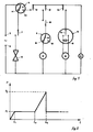
- the actuator solenoid 19 of a water supply solenoid valve is adapted to be connected between terminals 5 and 6 of an electric power supply via a circuit breaker 7 and a pressure switch 4 connected in series.
- the movable contact 9 of pressure switch 4 is adapted to connect terminal 5 to fixed contacts 41 or 42, respectively, when the pressure switch detects an "empty" or “full” state of a liquid collector receptacle provided in the machine.
- the washing machine also comprises an electric motor for rotating the drum of the machine; this motor includes a low-speed winding section 10 and a high-speed winding section 11.
- low-speed winding section 10 is adapted to be connected between terminals 5 and 6 through a series-connected circuit comprising pressure switch 4 (when detecting the "full" state), circuit breakers 12 and 13, and a per se known inverter 14 including a phase shift capacitor 15 having two fixed contacts selectively engageable by a movable contact 16 actuated by a fast cam.
- the high-speed winding section 11 of the motor on its part is adapted to be connected between terminals 5 and 6 by a series-connected circuit including pressure switch 4 (when detecting the "full" state), circuit breaker 12 and a pair of circuit breakers 17 and 18 actuated respectively by a slow cam and a fast cam of the program unit.
- high-speed winding section 11 is additionally connected to a further pressure switch 8 adapted to detect the pressure in the interior of the laundering tub of the machine.
- a movable contact 20 of pressure switch 8 is closed on a fixed contact 81 connected to high-speed winding section 11 as long as the pressure within the laundering tub is below a pre-determined value P2 (fig. 2) beyond which there occurs an excessive formation of foam.
- Pressure switch 8 is positioned and calibrated in such a manner that its movable contact 20 closes on a blind fixed contact 82 when the said pressure value P2 is detected.
- the circuit also includes a small electric motor 21 for advancing the timer, this motor being connected between terminals 5 and 6 by the series-connected circuit of pressure switch 4 and circuit breaker 12.
- circuit of fig. 1 is to be understood to include further functional components controlled by the program unit, such as a discharge pump, heater elements, a recirculation pump etc., these elements being not shown for the sake of simplification.
- the overall operation of the washing machine proceeds substantially as known.
- Solenoid valve 19 is actuated to admit water and detergent to the washing machine until pressure switch 4 detects a predetermined water level, causing its movable contact 9 to close on fixed contact 42 for energizing timer motor 21.
- the operation of the timer causes circuit breaker 13 to close for energizing low-speed winding section 10 of the drum motor, so that the drum is rotated at a low speed in alternating directions.
- the laundering liquid is concurrently heated and supplied to the interior of the drum so as to soak the laundry therein.
- the pressure within the laundering tub is stabilized at a value P1 as shown at t1 in fig. 2, this value remaining substantially constant.
- timer 21 at a predetermined instant operates to close circuit breaker 17, so that during an interval between the rotations of the drum in opposite directions as determined by inverter 14 circuit breaker 18 may be closed for energizing high-speed winding section 11 of the drum motor.
- the laundering drum is thus made to rotate at the speed for spin-drying the laundry, as described in the quoted patent application no.
- the laundering cycle then proceeds in the conventional manner, with circuit breakers 17 and 18 again opened and further reversals of the rotation of the drum at low speed, and with the possible intervention of further spin-drying phases similar to the one indicated at t2-t3.
- the washing machine may be of the combined function type capable of selectively operating with two different liquid levels as described in the quoted patent application no. 45715 A/85.
- the machine At the lower liquid level the machine would then operate with recirculation of the liquid and periodic spin-drying phases during the laundering cycle; at the higher liquid level the machine would operate in the conventional manner by agitating the laundry with or without liquid recirculation, but in any case without the intervention of spin-drying phases during the laundering cycle.
- control circuit is the advantageously designed as shown in fig. 3 by the provision of certain modifications of the circuit shown in fig. 1.
- pressure switch 8 is in this case connected between pressure switch 4 and circuit breaekr 12, its movable contact 20 being directly connected to fixed contact 42 of pressure switch 4, while its fixed contact 82 is connected to circuit breaker 12.
- fixed contact 81 of pressure switch 8 is connected respectively via further circuit breakers 22 and 23 to the junction between circuit breaker 7 and solenoid valve 9, and the junction between circuit breakers 12 and 17. Circuit breakers 22 and 23 are actuated by respective slow cams of the program unit.
- Solenoid valve 19 is energized via pressure switch 4 and circuit breaker 7 to admit water to the tub until the liquid attains the lower level, at which point movable contact 9 of pressostat 4 is caused to close on fixed contact 42. Solenoid valve 19 thus continues to be energized via pressure switch 4, pressure switch 8 and circuit breaker 22 until the liquid attains the high level, causing movable contact 20 of pressure switch 8 to close on fixed contact 82. The eventual closing of circuit breakers 13 and 16 during this phase results in low-speed winding section 10 to be energized, whereupon the laundering operation proceeds in the known manner which needs not be described. It is noted in this contect that pressure switch 8 in this case carries out the conventional function of controlling the maximum level of the liquid admitted to the washing machine.
- Solenoid valve 19 is actuated to admit water only until pressure switch 4 is actuated in response to detecting the "full" state; the laundering cycle then proceeds as already described with reference to fig. 1, that is, with recirculation of the laundering liquid to the interior of the drum and alternating rotation of the drum motor resulting from the simultaneous closing of circuit breakers 13 and 16.
- the combined closing of circuit breakers 17 and 18 at instant t2 results in the intervention of a spin-drying phase t2-t3.
- the laundering tub contains an amount of laundering liquid heated for instance to 60 °C, resulting in a pressure increase up to the value P2.
- movable contact 20 of pressure switch 8 is caused to close on fixed contact 82 to thereby interrupt the energization of high-speed winding section 11 and thus terminate the spin-drying phase.
- pressure switch 8 functions as a safety device effective to prevent the excessive formation of foam within the laundering tub to thus attain the stated object of the invention.
- the control circuit shown in fig. 3 thus requires only a single pressure switch 8 connected in series to pressure switch 4 for performing the double function of a conventional control element for the admission of water to the higher level and of a safety device for preventing the excessive formation of foam. This eliminates the necessity of providing an additional component specifically for performing the safety function to attain the object of the invention.
- washing machine may of course be variously modified within the purview of the invention.
- Motor 10, 11 may thus be of any other type suitable for this purpose.
- the program unit may similarly be of any other type to meet specific requirements.
- the spin-drying phase, or phases, t2-t3 may intervene at any suitable time other than the laundry washing cycle under suitable control by the program unit.
Landscapes
- Engineering & Computer Science (AREA)
- Textile Engineering (AREA)
- Control Of Washing Machine And Dryer (AREA)
Priority Applications (1)
| Application Number | Priority Date | Filing Date | Title |
|---|---|---|---|
| AT86115826T ATE64632T1 (de) | 1985-11-27 | 1986-11-14 | Automatische waschmaschine mit drehender trommel. |
Applications Claiming Priority (2)
| Application Number | Priority Date | Filing Date | Title |
|---|---|---|---|
| IT4575185 | 1985-11-27 | ||
| IT45751/85A IT1187301B (it) | 1985-11-27 | 1985-11-27 | Lavatrice automatica a tamburo rotante |
Publications (3)
| Publication Number | Publication Date |
|---|---|
| EP0224776A2 true EP0224776A2 (fr) | 1987-06-10 |
| EP0224776A3 EP0224776A3 (en) | 1988-03-02 |
| EP0224776B1 EP0224776B1 (fr) | 1991-06-19 |
Family
ID=11258053
Family Applications (1)
| Application Number | Title | Priority Date | Filing Date |
|---|---|---|---|
| EP86115826A Expired - Lifetime EP0224776B1 (fr) | 1985-11-27 | 1986-11-14 | Machine à laver automatique à tambour rotatif |
Country Status (4)
| Country | Link |
|---|---|
| EP (1) | EP0224776B1 (fr) |
| AT (1) | ATE64632T1 (fr) |
| DE (1) | DE3679889D1 (fr) |
| IT (1) | IT1187301B (fr) |
Cited By (1)
| Publication number | Priority date | Publication date | Assignee | Title |
|---|---|---|---|---|
| EP2246469A1 (fr) * | 2010-02-16 | 2010-11-03 | V-Zug AG | Lave-linge doté d'une pompe à circulation et d'une phase d'essorage |
Citations (6)
| Publication number | Priority date | Publication date | Assignee | Title |
|---|---|---|---|---|
| FR1123515A (fr) * | 1954-05-07 | 1956-09-24 | Dispositif électrique pour machines à laver pour empêcher une formation trop intense de mousse dans le cas d'une concentration trop forte en produit de lavage | |
| FR1501383A (fr) * | 1965-12-07 | 1967-11-10 | Siemens Elektrogeraete Gmbh | Installation pour contrôler l'ébullition d'un liquide |
| DE2325586A1 (de) * | 1973-05-19 | 1974-12-05 | Miele & Cie | Wasch- oder geschirrspuelmaschine mit einer einrichtung zur vermeidung des ueberschaeumens |
| EP0146719A2 (fr) * | 1983-12-06 | 1985-07-03 | INDUSTRIE ZANUSSI S.p.A. | Machine à laver le linge |
| GB2155051A (en) * | 1984-02-29 | 1985-09-18 | Fisher & Paykel | Improvements in or relating to clothes washing machines |
| EP0202509A2 (fr) * | 1985-05-24 | 1986-11-26 | INDUSTRIE ZANUSSI S.p.A. | Dispositif de commande pour machine à laver le linge |
-
1985
- 1985-11-27 IT IT45751/85A patent/IT1187301B/it active
-
1986
- 1986-11-14 DE DE8686115826T patent/DE3679889D1/de not_active Expired - Lifetime
- 1986-11-14 AT AT86115826T patent/ATE64632T1/de not_active IP Right Cessation
- 1986-11-14 EP EP86115826A patent/EP0224776B1/fr not_active Expired - Lifetime
Patent Citations (6)
| Publication number | Priority date | Publication date | Assignee | Title |
|---|---|---|---|---|
| FR1123515A (fr) * | 1954-05-07 | 1956-09-24 | Dispositif électrique pour machines à laver pour empêcher une formation trop intense de mousse dans le cas d'une concentration trop forte en produit de lavage | |
| FR1501383A (fr) * | 1965-12-07 | 1967-11-10 | Siemens Elektrogeraete Gmbh | Installation pour contrôler l'ébullition d'un liquide |
| DE2325586A1 (de) * | 1973-05-19 | 1974-12-05 | Miele & Cie | Wasch- oder geschirrspuelmaschine mit einer einrichtung zur vermeidung des ueberschaeumens |
| EP0146719A2 (fr) * | 1983-12-06 | 1985-07-03 | INDUSTRIE ZANUSSI S.p.A. | Machine à laver le linge |
| GB2155051A (en) * | 1984-02-29 | 1985-09-18 | Fisher & Paykel | Improvements in or relating to clothes washing machines |
| EP0202509A2 (fr) * | 1985-05-24 | 1986-11-26 | INDUSTRIE ZANUSSI S.p.A. | Dispositif de commande pour machine à laver le linge |
Cited By (1)
| Publication number | Priority date | Publication date | Assignee | Title |
|---|---|---|---|---|
| EP2246469A1 (fr) * | 2010-02-16 | 2010-11-03 | V-Zug AG | Lave-linge doté d'une pompe à circulation et d'une phase d'essorage |
Also Published As
| Publication number | Publication date |
|---|---|
| EP0224776A3 (en) | 1988-03-02 |
| ATE64632T1 (de) | 1991-07-15 |
| EP0224776B1 (fr) | 1991-06-19 |
| IT8545751A0 (it) | 1985-11-27 |
| IT1187301B (it) | 1987-12-23 |
| DE3679889D1 (de) | 1991-07-25 |
Similar Documents
| Publication | Publication Date | Title |
|---|---|---|
| EP0182364B1 (fr) | Machine à laver le linge | |
| EP0146719B1 (fr) | Machine à laver le linge | |
| US4794661A (en) | Process for the treatment of laundry in a washing machine | |
| US4631771A (en) | Clothes washing machines | |
| US4711103A (en) | Controlling device for clothes washing machine | |
| US2579598A (en) | Control for automatic washing machines | |
| EP0629733B1 (fr) | Machine pour laver et rincer le linge | |
| EP0224776B1 (fr) | Machine à laver automatique à tambour rotatif | |
| US3129361A (en) | Control mechanism for laundering equipment | |
| US3148523A (en) | Laundry apparatus | |
| EP0300295B1 (fr) | Procédé pour laver du linge ou matériau similaire et machine pour exécuter ce procédé | |
| CA2035320C (fr) | Laveuse automatique a tambour | |
| CA1148375A (fr) | Essorage par centrifugation basse vitesse sur lessiveuse automatique | |
| EP0278461B1 (fr) | Dispositif de commande de programme pour machine à laver | |
| US3005328A (en) | Automatic washing machines | |
| EP0452678B1 (fr) | Dispositif de commande pour machine à laver et à sécher le linge | |
| EP0687761B1 (fr) | Machine à laver à programmes multiples avec un programmateur électromécanique et un microcontrôleur digital | |
| JP2001187296A (ja) | 洗濯機 | |
| US2934926A (en) | Control arrangement for clothes washing machine | |
| EP0331149B1 (fr) | Dispositif pour commander l'admission de détergents liquides dans une machine à laver | |
| EP0553645B1 (fr) | Dispositif de commande pour l'essorage dans les machines à laver | |
| FI83889C (fi) | Tvaettmaskin vars styrprogram aer beroende av tvaettbelastningen. | |
| EP0224145B1 (fr) | Machine à laver automatique à tambour rotatif | |
| JPS6131756Y2 (fr) | ||
| EP0738797B1 (fr) | Machine à laver avec sélecteur de température |
Legal Events
| Date | Code | Title | Description |
|---|---|---|---|
| PUAI | Public reference made under article 153(3) epc to a published international application that has entered the european phase |
Free format text: ORIGINAL CODE: 0009012 |
|
| AK | Designated contracting states |
Kind code of ref document: A2 Designated state(s): AT BE CH DE FR GB IT LI LU NL SE |
|
| PUAL | Search report despatched |
Free format text: ORIGINAL CODE: 0009013 |
|
| RAP1 | Party data changed (applicant data changed or rights of an application transferred) |
Owner name: INDUSTRIE ZANUSSI S.P.A. |
|
| AK | Designated contracting states |
Kind code of ref document: A3 Designated state(s): AT BE CH DE FR GB IT LI LU NL SE |
|
| 17P | Request for examination filed |
Effective date: 19880726 |
|
| 17Q | First examination report despatched |
Effective date: 19900801 |
|
| ITF | It: translation for a ep patent filed | ||
| GRAA | (expected) grant |
Free format text: ORIGINAL CODE: 0009210 |
|
| AK | Designated contracting states |
Kind code of ref document: B1 Designated state(s): AT BE CH DE FR GB IT LI LU NL SE |
|
| REF | Corresponds to: |
Ref document number: 64632 Country of ref document: AT Date of ref document: 19910715 Kind code of ref document: T |
|
| ET | Fr: translation filed | ||
| REF | Corresponds to: |
Ref document number: 3679889 Country of ref document: DE Date of ref document: 19910725 |
|
| PG25 | Lapsed in a contracting state [announced via postgrant information from national office to epo] |
Ref country code: LU Free format text: LAPSE BECAUSE OF NON-PAYMENT OF DUE FEES Effective date: 19911130 Ref country code: CH Effective date: 19911130 Ref country code: BE Effective date: 19911130 Ref country code: LI Effective date: 19911130 |
|
| PLBE | No opposition filed within time limit |
Free format text: ORIGINAL CODE: 0009261 |
|
| STAA | Information on the status of an ep patent application or granted ep patent |
Free format text: STATUS: NO OPPOSITION FILED WITHIN TIME LIMIT |
|
| BERE | Be: lapsed |
Owner name: INDUSTRIE ZANUSSI S.P.A. Effective date: 19911130 |
|
| PG25 | Lapsed in a contracting state [announced via postgrant information from national office to epo] |
Ref country code: NL Effective date: 19920601 |
|
| 26N | No opposition filed | ||
| NLV4 | Nl: lapsed or anulled due to non-payment of the annual fee | ||
| REG | Reference to a national code |
Ref country code: CH Ref legal event code: PL |
|
| EAL | Se: european patent in force in sweden |
Ref document number: 86115826.9 |
|
| REG | Reference to a national code |
Ref country code: GB Ref legal event code: IF02 |
|
| PGFP | Annual fee paid to national office [announced via postgrant information from national office to epo] |
Ref country code: AT Payment date: 20051011 Year of fee payment: 20 |
|
| PGFP | Annual fee paid to national office [announced via postgrant information from national office to epo] |
Ref country code: FR Payment date: 20051013 Year of fee payment: 20 |
|
| PGFP | Annual fee paid to national office [announced via postgrant information from national office to epo] |
Ref country code: GB Payment date: 20051018 Year of fee payment: 20 |
|
| PGFP | Annual fee paid to national office [announced via postgrant information from national office to epo] |
Ref country code: SE Payment date: 20051024 Year of fee payment: 20 |
|
| PGFP | Annual fee paid to national office [announced via postgrant information from national office to epo] |
Ref country code: DE Payment date: 20051026 Year of fee payment: 20 |
|
| PGFP | Annual fee paid to national office [announced via postgrant information from national office to epo] |
Ref country code: IT Payment date: 20051118 Year of fee payment: 20 |
|
| PG25 | Lapsed in a contracting state [announced via postgrant information from national office to epo] |
Ref country code: GB Free format text: LAPSE BECAUSE OF EXPIRATION OF PROTECTION Effective date: 20061113 |
|
| REG | Reference to a national code |
Ref country code: GB Ref legal event code: PE20 |
|
| EUG | Se: european patent has lapsed |