EP0223946A2 - Oxygen producer comprising a high-pressure container and a cartridge support for combustible-oxygen cartridges - Google Patents
Oxygen producer comprising a high-pressure container and a cartridge support for combustible-oxygen cartridges Download PDFInfo
- Publication number
- EP0223946A2 EP0223946A2 EP86112588A EP86112588A EP0223946A2 EP 0223946 A2 EP0223946 A2 EP 0223946A2 EP 86112588 A EP86112588 A EP 86112588A EP 86112588 A EP86112588 A EP 86112588A EP 0223946 A2 EP0223946 A2 EP 0223946A2
- Authority
- EP
- European Patent Office
- Prior art keywords
- oxygen generator
- housing
- oxygen
- generator according
- pressure vessel
- Prior art date
- Legal status (The legal status is an assumption and is not a legal conclusion. Google has not performed a legal analysis and makes no representation as to the accuracy of the status listed.)
- Withdrawn
Links
Images

Classifications
-
- B—PERFORMING OPERATIONS; TRANSPORTING
- B01—PHYSICAL OR CHEMICAL PROCESSES OR APPARATUS IN GENERAL
- B01J—CHEMICAL OR PHYSICAL PROCESSES, e.g. CATALYSIS OR COLLOID CHEMISTRY; THEIR RELEVANT APPARATUS
- B01J7/00—Apparatus for generating gases
-
- C—CHEMISTRY; METALLURGY
- C01—INORGANIC CHEMISTRY
- C01B—NON-METALLIC ELEMENTS; COMPOUNDS THEREOF; METALLOIDS OR COMPOUNDS THEREOF NOT COVERED BY SUBCLASS C01C
- C01B13/00—Oxygen; Ozone; Oxides or hydroxides in general
- C01B13/02—Preparation of oxygen
- C01B13/0296—Generators releasing in a self-sustaining way pure oxygen from a solid charge, without interaction of it with a fluid nor external heating, e.g. chlorate candles or canisters containing them
Definitions
- the invention relates to an oxygen generator for combustible and in the burning state oxygen-emptying cartridges, with a pressure vessel and a cartridge holder connected to it, which is divided into two partial housings by a gas-tight clutch and the interior of which communicates with the interior of the pressure vessel via an opening.
- an oxygen generator of the type described in the introduction in which the cartridge holder has at one end, in addition to the separating coupling, a connection thread with which it can be connected as a structural unit interchangeably with pressurized gas cylinders which have a corresponding connection thread. If the compressed gas cylinders have a check valve in the area of the connecting thread, the pressure in the compressed gas cylinder is retained even after the cartridge holder has been unscrewed.
- both partial housings are provided with cooling fins in the known solution
- a relatively high temperature is set at the separating clutch located approximately in the axial center of the cartridge, through which the separating coupling designed as a screw thread gradually becomes stiff and the seal in the separating coupling is subjected to high thermal loads becomes.
- the firing temperature of the cartridge on the surface may well be 650 ° C and that the firing zone migrates through the clutch. This leads to an additional temperature rise with correspondingly larger thermal problems in the case of short consecutive loads with fresh cartridges.
- An oxygen generator is known from US Pat. No. 2,775,511, in which the one-piece cartridge holder lies completely outside the pressure container, so that it cannot support the cartridge holder during cooling.
- the cartridge holder is provided with very large cooling fins, a seal between the cartridge holder and a sealing cap is also subjected to very high thermal loads.
- the cartridge holder is ver with the pressure vessel via a relatively long pipe protruding into the pressure vessel bound, at the end of which a check valve is arranged. If this were not present, then a cleaning liquid present in the pressure container would be thrown out by the latter with the upper pressure still present and when the cartridge holder was opened.
- the check valve also leads to a pressure increase when the cartridge holder is loaded several times without corresponding oxygen consumption, which pressure must be limited by a safety valve. As a result, the known device has a relatively very complicated structure.
- a check valve between the cartridge holder and the pressure container also has the consequence in the device according to EP-OS 0 142 730 that in the case of multiple charging of new cartridges a corresponding pressure increase occurs, which must be limited by an overpressure valve.
- the invention is therefore based on the object of specifying an oxygen generator of the type described at the outset, in which the smoothness and tightness of the separating clutch is retained over a long period of time and in which, even without a non-return valve, the remaining amount of oxygen remaining in the pressure vessel is very diluted by the nitrogen in the ambient air is largely prevented.
- the separating clutch is arranged approximately in the axial center of the cartridge.
- This process is further promoted in that the part of the cartridge holder lying outside the compressed gas bottle is produced in a particularly advantageous manner from a good heat-conducting material such as brass and is additionally provided with cooling fins.
- the part of the heat generated there is given off by heat conduction to the mass of the relatively thick-walled compressed gas bottle, so it is distributed in this way and is subsequently distributed over the relatively large surface area of the compressed gas bottle released into the ambient air. Since the good heat-conducting connection is present in the area of the separating clutch, it is cooled very effectively, including the associated seal, so that its functionality is maintained over a very long time.
- a hole that is limited in relation to the inner cross-section of the cartridge holder and is constantly open with respect to the interior of the compressed gas bottle prevents a susceptible check valve and at the same time prevents a noticeable proportion of air from entering the compressed gas bottle when the cartridge holder is opened or the cartridge is replaced (throttling effect).
- An extremely minor gas exchange is only possible through diffusion, that is, through an extremely slow process.
- the unlocked bore provides an additional safety factor against an overpressure: with every cartridge change, oxygen that is still under pressure must necessarily escape through the bore and the (open) cartridge holder, so that each filling process begins at atmospheric pressure and a gradual build-up of pressure is excluded. A possibly failing pressure relief valve does not pose any danger to the operator.
- oxygen of constant purity can be taken from the oxygen generator from the start, so that there are no problems with regard to the burning behavior of a flame supplied with the oxygen.
- the composition of the oxygen before and after a charging process is the more uniform the smaller the volume of the cartridge holder that is in front of the narrow bore mentioned and that is necessarily ventilated when the cartridge is changed.
- the cartridge holder should therefore surround the cartridge as closely as possible, ie with a distance of one millimeter and less. It is therefore particularly expedient if the volume ratio between the interior of the cartridge holder and the interior of the pressure vessel is between 1:10 and 1:60.
- the internal volume of the cartridge holder with respect to standardized cartridges can be between approximately 80 and 100 cm 3 , while the pressure container preferably has a volume of 4000 cm 3 .
- a sufficiently large amount of material can be accommodated in the jacket of the pressure vessel, which is also used for heat dissipation. This is particularly the case if the wall thickness of the pressure container in the area of the cartridge holder is at least 1.5 mm, preferably at least 2.0 mm. With a practically implemented wall thickness of 3 mm and a longer interval between charging processes, the temperature in the separating coupling does not rise above the value of approximately 80 ° C.
- Cartridges in particular caseless cartridges, from a mixture of chemical compounds from which oxygen is released by an exothermic reaction have long been known.
- it is a mixture of an alkali metal chlorate or perchlorate and an oxidizable substance which, when burned after an ignition process, provides just enough heat to cause the reaction to proceed at an approximately constant rate of migration in the cartridge, continuously releasing excess oxygen becomes.
- the reaction mixture forms a solid, pressed body, namely the cartridge mentioned.
- the temperature in the reaction zone is about 650 ° C.
- Such standardized cartridges have a diameter of 2.7 cm and a length of 11.7 cm, thus a volume of approximately 67 cm 3 .
- Such a cartridge provides an average of about 30 1 oxygen at normal pressure, so that a pressure vessel with a volume of approximately 4 l can be filled to a pressure of just under 8 bar.
- the oxygen generator according to the invention it is possible to refill the pressure vessel quickly and cheaply, even on Sundays and public holidays, i.e. the typical "home improvement days".
- the cartridges can be safely stored in large quantities without moisture.
- the price for the refill is about 20% of the price of a commercially available, filled compressed gas bottle.
- Oxygen companies charge high fees for the bottle cycle. While refilling itself is cheap, transportation and administration are costly.
- Refilling a pressure tank is also environmentally friendly, since a large number of the empty compressed gas cylinders no longer end up in the garbage.
- the burned-off cartridges themselves consist of harmless salts, especially table salts, as well as oxides of the flammable components. The used cartridges therefore pose no danger to the environment.
- the subject of the invention is used in connection with a fuel gas bottle for welding and brazing with small and very small torches down to the micro torch.
- the subject of the invention is suitable for all kinds of handicraft work, goldsmith work, for model making and repair work, in the field of refrigeration technology and for work in dental laboratories.
- Fuel gases with proportions of acetylene are also suitable.
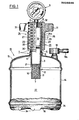
- Figure 1 shows a cartridge holder 1, which consists of two sleeve-shaped partial housings 2 and 3, which are connected to each other via a separating coupling 4, which is designed as a screw thread and is sealed by a sealing ring 5.
- the sub-housings 2 and 3 have end walls 6 and 7, respectively.
- a threaded connector 8 of a pressure meter 9 is screwed into the end wall 6 and measures the pressure in the entire system.
- the end wall 7 is the lower boundary wall of a tapered cylindrical extension 10 of the partial housing 3, in which there is a filter material 11 and a narrow side bore 12 for the escape of oxygen.
- the lower part of the housing 3 is inserted in the area of the separating clutch 4 with good thermal conductivity in a pressure vessel 13 which has a cylindrical jacket 14 and a cover 15 and a bottom 16.
- the cover 15 is provided with a coaxial collar 17 to which the partial housing 3 is welded.
- the sub-housings 2 and 3 enclose an inner space 19 which serves to accommodate the cartridge 20 described, the outline of which is indicated here only by a dash-dotted line.
- Cartridges of this type are commercially available, for example, under the name "SOLIDOX”.
- the cartridge 20 rests on a spacer 21, the opposite side of which faces the filter material 11 is.
- a layering of chamotte granulate and rock wool can serve as filter material, for example.
- the edge of the spacer 21 has a profile, not shown here, by means of which the gas can pass from the space 19 into the extension 10.
- the cross section of the bore 12 is small in relation to the inner cross section of the lower housing part 3, so that gas exchange between the (opened) cartridge holder 1 and the interior 22 of the pressure container 13 is made more difficult.
- the upper part of the housing 2 can be seen placed directly above the pressure container 13 on the lower part of the housing 3 and provided with a cooling device 24 which is formed by a plurality of cooling fins. This creates a temperature gradient through which the temperature of the device in the area of the separating clutch 4 is markedly reduced. Even after using the device, a faster heat exchange with the surroundings is made possible, so that the device is ready for operation again in the short term.
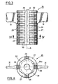
- the partial housing 2 is provided with heat protection 25 over practically its entire length, which consists of a heat-insulating material with high temperature resistance and will be explained in more detail with reference to FIG. 3.
- the upper part of the housing 2 which consists of a hexagonal rod made of brass, in which grooves 26 are pierced in an equidistant distribution with a cylindrical groove base 26a, whereby cooling fins 24a of the cooling device 24 are formed.
- the upper part of the housing 2 has an internal thread 4a, while the lower part of the housing 3 has a complementary external thread, not specified, which together form the separating coupling 4 (FIG. 1).
- the grooves 26b have a smaller depth only in the area of the separating clutch 4.
- the threaded bore 6a provided in the end wall 6 serves to screw in the pressure gauge 9.
- FIG. 3 and 4 show details of the heat protection 25 in the radial plan view of its longitudinal axis AA or in section along the diametrical line IV-IV.
- the heat protection 25 consists of a plurality of rings 27 arranged coaxially one behind the other, which are connected to one another on the circumference by axially parallel webs 28 and 29.
- ventilation openings 30 are formed between the rings 27 and the webs 28 and 29, which are delimited by the parallel walls of the rings 27 and form a kind of sector-shaped slots (FIG. 4). It can be seen that the rings 27 are aligned with the cooling fins 24a, so that the grooves 26 between the cooling fins 24a communicate freely with the atmosphere (FIG. 1).
- the heat protection 25 is provided with radially projecting handles 31, which give the heat protection the properties of a "wing nut".
- the handles 31 are arranged on the diametrically opposite webs 29, while between these webs 29 provided with handles the further webs 28 are also offset by 90 degrees and are likewise arranged diametrically opposite one another.
- the cross section of the outer envelope surface of the cooling fins 24a is indicated by a dash-dotted hexagon. It can be seen that the rings 27 or the webs 28 are formed at the corners of this hexagon complementary to the cooling fins, so that a positive connection in the circumferential direction is formed between the heat protection 25 and the associated part housing 2. In the direction of the axis A-A, however, the heat protection 25 can be easily pushed onto the partial housing 2.
- the cylindrical groove base 26a is indicated by a dash-dotted circle, and it can be seen that there is a sufficient radial distance between this groove base and the webs 28 and 29, which ventilation on all sides and thus good cooling of the part housing 2nd also possible in the area of the groove base.
- the heat protection 25 has in the region of the handles 31 an end wall 32 with a bore 33 for the threaded supports 8. After the pressure gauge 9 has been screwed in, the heat protection 25 is fixed on the partial housing 2 so that it cannot move in the axial direction.
- the heat protection 25 can be easily removed from a mold having a complementary design if the parting line of the mold is placed in the direction of a plane of symmetry running through the handles 31.
- the mold can then consist of only two mold halves without movable insert parts and a mold core.
- the lower part of the housing 3 is an easily produced rotating part, in which only the inside diameter is graduated in order to form an annular shoulder for the support of the spacer 21.
- the pressure vessel 13 has a plurality of cup-shaped depressions 34 located on the outer periphery 16 thereof. These depressions (six in number) serve at the same time as stand-up feet and as a collecting container for condensation water forming in the device, so that it cannot collect centrally at a single point on the floor. It is possible to provide the container with a closable drainage opening in the bottom area.
- the cartridge (s) are replaced by unscrewing the partial housing 2 together with the heat protection 25 designed as a wing nut.
Landscapes
- Chemical & Material Sciences (AREA)
- Organic Chemistry (AREA)
- Inorganic Chemistry (AREA)
- Chemical Kinetics & Catalysis (AREA)
- Filling Or Discharging Of Gas Storage Vessels (AREA)
- Oxygen, Ozone, And Oxides In General (AREA)
Abstract
Sauerstofferzeuger für Patronen (20) mit einem Druckbehälter (13) und einem mit diesem verbundenen Patronenhalter (1). Der Patronenhalter ist durch eine gasdichte Trennkupplung (4) in zwei Teilgehäuse (2.3) unterteilt, und sein Innenraum (19) steht über eine Öffnung (12) mit dem Innenraum (22) des Druckbehälters (13) in Verbindung. Zur Erhaltung der Funktionstüchtigkeit über lange Zeit ist das untere Teilgehäuse (3) im Bereich der Trennkupplung (4) gut wärmeleitend mit dem Druckbehälter (13) verbunden und steht mit diesem über die im Verhältnis zum Innenquerschnitt des unteren Teilgehäuses (3) enge und unverschlossene Öffnung (12) in Verbindung. Weiterhin ist das obere Teilgehäuse unmittelbar oberhalb des Druckbehälters (13) auf das untere Teilgehäuse (3) aufgesetzt und mit einer Kühleinrichtung (24) versehen.Oxygen generator for cartridges (20) with a pressure container (13) and a cartridge holder (1) connected to it. The cartridge holder is divided into two partial housings (2.3) by a gas-tight coupling (4), and its interior (19) communicates with the interior (22) of the pressure vessel (13) via an opening (12). To maintain functionality over a long period of time, the lower part housing (3) in the area of the separating coupling (4) is connected to the pressure container (13) with good heat conduction and is connected to the pressure container (13) via the narrow and unlocked opening in relation to the internal cross section of the lower part housing (3) (12) in connection. Furthermore, the upper part of the housing is placed directly above the pressure vessel (13) on the lower part of the housing (3) and provided with a cooling device (24).
Description
Die Erfindung betrifft einen Sauerstofferzeuger für brennbare und in brennendem Zustand sauerstoffabgebende Patronen, mit einem Druckbehälter und einem mit diesem verbundenen Patronenhalter, der durch eine gasdichte Trennkupplung in zwei Teilgehäuse unterteilt ist und dessen Innenraum mit dem Innenraum des Druckbehälters über eine Öffnung in Verbindung steht.The invention relates to an oxygen generator for combustible and in the burning state oxygen-emptying cartridges, with a pressure vessel and a cartridge holder connected to it, which is divided into two partial housings by a gas-tight clutch and the interior of which communicates with the interior of the pressure vessel via an opening.
Durch die EP-OS 0 142 730 ist ein Sauerstofferzeuger der eingangs beschriebenen Gattung bekannt, bei dem der Patronenhalter an seinem einen Ende zusätzlich zur Trennkupplung ein Anschlußgewinde aufweist, mit dem er als Baueinheit auswechselbar mit Druckgasflaschen verbindbar ist, die ein entsprechendes Anschlußgewinde aufweisen. Soweit die Druckgasflaschen dabei im Bereich des Anschlußgewindes ein Rückschlagventil aufweisen, bleibt der jeweils in der Druckgasflasche vorhandene Druck auch nach dem Abschrauben des Patronenhalters erhalten.From EP-OS 0 142 730 an oxygen generator of the type described in the introduction is known, in which the cartridge holder has at one end, in addition to the separating coupling, a connection thread with which it can be connected as a structural unit interchangeably with pressurized gas cylinders which have a corresponding connection thread. If the compressed gas cylinders have a check valve in the area of the connecting thread, the pressure in the compressed gas cylinder is retained even after the cartridge holder has been unscrewed.
Obwohl beide Teilgehäuse bei der bekannten Lösung mit Kühlrippen versehen sind, stellt sich an der etwa in der axialen Mitte der Patrone liegenden Trennkupplung eine relativ hohe Temperatur ein, durch die die als Schraubgewinde ausgeführte Trennkupplung allmählich schwergängig und die in der Trennkupplung vorhandene Dichtung thermisch hoch belastet wird. Hierbei ist zu beachten, daß die Brenntemperatur der Patrone an der Oberfläche durchaus 650 °C betragen kann und daß die Brennzone durch die Trennkupplung hindurchwandert. Dies führt bei kurz aufeinanderfolgenden Beschickungen mit frischen Patronen zu einem zusätzlichen Temperaturanstieg mit entsprechend größeren thermischen Problemen.Although both partial housings are provided with cooling fins in the known solution, a relatively high temperature is set at the separating clutch located approximately in the axial center of the cartridge, through which the separating coupling designed as a screw thread gradually becomes stiff and the seal in the separating coupling is subjected to high thermal loads becomes. It should be noted here that the firing temperature of the cartridge on the surface may well be 650 ° C and that the firing zone migrates through the clutch. This leads to an additional temperature rise with correspondingly larger thermal problems in the case of short consecutive loads with fresh cartridges.
Durch die DE-OS 24 61 681 ist es bereits bekannt, einen einteiligen Patronenhalter vollständig innerhalb eines Druckbehälters unterzubringen, so daß die gesamte Wärmeentwicklung Innerhalb des Druckbehälters stattfindet und diesen thermisch hoch belastet, so daß besondere Vorkehrungen für einen Schutz des Druckbehälters gegen Korrosion getroffen werden müssen. Hinzukommt, daß der Patronenhalter zum Patronenwechsel aus einer entsprechend groß dimensionierten öffnung herausgenommen werden muß, so daß bei einem Patronenwechsel der ursprUnglich praktisch reine Sauerstoff durch Umgebungsluft mit einem Stickstoffanteil von ca. 80 % ersetzt wird. Dies führt zu einem schwer kontrollierbaren Brennverhalten einer durch den Sauerstofferzeuger versorgten Flamme, da der Sauerstoffanteil erst allmählich von etwa 20 % auf nahezu 100 % anwächst. Dieses Spiel wiederholt sich bei jedem Patronenwechsel von Neuem.From DE-OS 24 61 681 it is already known to accommodate a one-piece cartridge holder completely within a pressure vessel, so that the Total heat development takes place within the pressure vessel and places a high thermal load on it, so that special precautions must be taken to protect the pressure vessel against corrosion. In addition, the cartridge holder must be removed from a correspondingly large opening to change the cartridge, so that when the cartridge is changed, the originally practically pure oxygen is replaced by ambient air with a nitrogen content of approximately 80%. This leads to a difficult-to-control burning behavior of a flame supplied by the oxygen generator, since the proportion of oxygen only gradually increases from about 20% to almost 100%. This game repeats itself every time you change cartridges.
Durch die US-PS 2 775 511 ist ein Sauerstofferzeuger bekannt, bei dem der einteilige Patronenhalter vollständig außerhalb des Druckbehälters liegt, so daß dieser den Patronenhalter bei der Kühlung nicht unterstützen kann. Zwar ist der Patronenhalter mit sehr großflächigen Kühlrippen versehen, jedoch wird auch hierbei eine zwischen dem Patronenhalter und einem Verschlußdeckel vorhandene Dichtung thermisch sehr hoch belastet. Der Patronenhalter ist mit dem Druckbehälter über eine verhältnismäßig lange, in den Druckbehälter hineinragende Rohrleitung verbunden, an deren Ende ein Rückschlagventil angeordnet ist. Wäre dieses nicht vorhanden, dann würde eine in dem Druckbehälter vorhandene Reinigungsflüssigkeit bei noch vorhandenem Oberdruck und beim öffnen des Patronenhalters durch diesen herausgeschleudert. Das Rückschlagventil führt darüberhinaus bei einer Mehrfachbeschickung des Patronenhalters ohne entsprechenden Sauerstoffverbrauch zu einem Druckanstieg, der durch ein Sicherheitsventil begrenzt werden muß. Dadurch hat die bekannte Vorrichtung einen relativ sehr komplizierten Aufbau.An oxygen generator is known from US Pat. No. 2,775,511, in which the one-piece cartridge holder lies completely outside the pressure container, so that it cannot support the cartridge holder during cooling. Although the cartridge holder is provided with very large cooling fins, a seal between the cartridge holder and a sealing cap is also subjected to very high thermal loads. The cartridge holder is ver with the pressure vessel via a relatively long pipe protruding into the pressure vessel bound, at the end of which a check valve is arranged. If this were not present, then a cleaning liquid present in the pressure container would be thrown out by the latter with the upper pressure still present and when the cartridge holder was opened. The check valve also leads to a pressure increase when the cartridge holder is loaded several times without corresponding oxygen consumption, which pressure must be limited by a safety valve. As a result, the known device has a relatively very complicated structure.
Ein Rückschlagventil zwischen Patronenhalter und Druckbehälter hat auch bei der Vorrichtung nach der EP-OS 0 142 730 zur Folge, daß im Falle einer Mehrfachchargierung neuer Patronen ein entsprechender Druckanstieg eintritt, der durch ein Oberdruckventil begrenzt werden muß.A check valve between the cartridge holder and the pressure container also has the consequence in the device according to EP-OS 0 142 730 that in the case of multiple charging of new cartridges a corresponding pressure increase occurs, which must be limited by an overpressure valve.
Der Erfindung liegt daher die Aufgabe zugrunde, einen Sauerstofferzeuger der eingangs beschriebenen Gattung anzugeben, bei der die Leichtgängigkeit und Dichtigkeit der Trennkupplung über lange Zeit erhalten bleibt und bei der auch ohne Rückschlagventil eine Verdünnung der restlichen, im Druckbehälter zurückbleibenden Sauerstoffmenge durch den Stickstoff der Umgebungsluft sehr weitgehend verhindert wird.The invention is therefore based on the object of specifying an oxygen generator of the type described at the outset, in which the smoothness and tightness of the separating clutch is retained over a long period of time and in which, even without a non-return valve, the remaining amount of oxygen remaining in the pressure vessel is very diluted by the nitrogen in the ambient air is largely prevented.
Die Lösung der gestellten Aufgabe erfolgt bei dem eingangs angegebenen Sauerstofferzeuger erfindungsgemäß dadurch, daß
- a) das untere Teilgehäuse im Bereich der Trennkupplung gut wärmeleitend in den Druckbehälter eingesetzt istund mit diesem über die im Verhältnis zum Innenquerschnittdes unteren Teilgehäuses enge und unverschlossene Uffnung in Verbindung steht, und
- b) das obere Teilgehäuse unmittelbar oberhalb des Druckbehälters auf das untere Teilgehäuse aufgesetzt und mit einer Kühleinrichtung versehen ist.
- a) the lower part of the housing is inserted in the area of the separating coupling with good heat conductivity in the pressure vessel and is connected to it via the narrow and unlocked opening in relation to the inner cross section of the lower part of the housing, and
- b) the upper part of the housing is placed directly above the pressure vessel on the lower part of the housing and is provided with a cooling device.
Es ist dabei besonders vorteilhaft, wenn die Trennkupplung etwa in der axialen Mitte der Patrone angeordnet ist.It is particularly advantageous if the separating clutch is arranged approximately in the axial center of the cartridge.
Durch das Herausragen des Patronenhalters, vorzugsweise mit etwa der Hälfte seiner Länge, aus der Druckgasflasche wird ein beträchtlicher Teil der Wärmemenge außerhalb der Druckgasflasche entwickelt und auch dort auf dem kürzest möglichen Wege an die Umgebungsluft abgegeben.By protruding the cartridge holder, preferably with about half its length, from the compressed gas bottle, a considerable part of the amount of heat is developed outside the compressed gas bottle and also released there to the ambient air in the shortest possible way.
Dieser Vorgang wird noch dadurch begünstigt, daß man in besonders vorteilhafter Weise den außerhalb der Druckgasflasche liegenden Teil des Patronenhalters aus einem gut wärmeleitenden Werkstoff wie Messing herstellt und ihn zusätzlich mit Kühlrippen versieht.This process is further promoted in that the part of the cartridge holder lying outside the compressed gas bottle is produced in a particularly advantageous manner from a good heat-conducting material such as brass and is additionally provided with cooling fins.
Durch die gut wärmeleitende Verbindung der unteren, beispielsweise aus Stahl bestehenden, Hälfte des Patronenhalters wird der dort entstehende Teil der Wärme durch Wärmeleitung an die Masse der verhältnismäßig starkwandigen Druckgasflasche abgegeben, verteilt sich also auf diese Weise und wird nachfolgend über die verhältnismäßig große Oberfläche der Druckgasflasche an die Umgebungsluft abgegeben. Da die gut wärmeleitende Verbindung im Bereich der Trennkupplung vorhanden ist, wird diese einschließlich der zugehörigen Dichtung sehr wirksam gekühlt, so daß ihre Funktionsfähigkeit über sehr lange Zeit erhalten bleibt.Due to the good heat-conducting connection of the lower half, for example made of steel, of the cartridge holder, the part of the heat generated there is given off by heat conduction to the mass of the relatively thick-walled compressed gas bottle, so it is distributed in this way and is subsequently distributed over the relatively large surface area of the compressed gas bottle released into the ambient air. Since the good heat-conducting connection is present in the area of the separating clutch, it is cooled very effectively, including the associated seal, so that its functionality is maintained over a very long time.
Durch eine im Verhältnis zum Innenquerschnitt des Patronenhalters begrenzte, gegenüber dem Innenraum der Druckgasflasche ständig offene Bohrung wird ein anfälliges Rückschlagventil vermieden und gleichzeitig verhindert, daß beim Uffnen des Patronenhalters bzw. Auswechseln der Patrone ein merklicher Anteil von Luft in die Druckgasflasche eintritt (Drosseleffekt). Ein äußerst geringfügiger Gasaustausch ist allenfalls durch Diffusion möglich, also durch einen extrem langsam ablaufenden Vorgang.A hole that is limited in relation to the inner cross-section of the cartridge holder and is constantly open with respect to the interior of the compressed gas bottle prevents a susceptible check valve and at the same time prevents a noticeable proportion of air from entering the compressed gas bottle when the cartridge holder is opened or the cartridge is replaced (throttling effect). An extremely minor gas exchange is only possible through diffusion, that is, through an extremely slow process.
Vor allem aber bietet die unverschlossene Bohrung einen zusätzlichen Sicherheitsfaktor gegen einen Oberdruck: Bei jedem Patronenwechsel muß notwendigerweise etwa noch unter Druck stehender Sauerstoff durch die Bohrung und den (offenen) Patronenhalter entweichen, so daß jeder Füllvorgang bei Atmosphärendruck beginnt und ein stufenweiser Druckaufbau ausgeschlossen ist. Ein etwa versagendes Oberdruckventil stellt also keine Gefahr für die Bedienungsperson dar.Above all, however, the unlocked bore provides an additional safety factor against an overpressure: with every cartridge change, oxygen that is still under pressure must necessarily escape through the bore and the (open) cartridge holder, so that each filling process begins at atmospheric pressure and a gradual build-up of pressure is excluded. A possibly failing pressure relief valve does not pose any danger to the operator.
Insbesondere kann dem Sauerstofferzeuger von Anfang an Sauerstoff gleichbleibender Reinheit entnommen werden, so daß sich keine Probleme hinsichtlich des Brennverhaltens einer mit dem Sauerstoff versorgten Flamme ergeben.In particular, oxygen of constant purity can be taken from the oxygen generator from the start, so that there are no problems with regard to the burning behavior of a flame supplied with the oxygen.
Die Zusammensetzung des Sauerstoffs vor und nach einem Chargiervorgang ist dabei um so gleichförmiger, je kleiner dasjenige Volumen des Patronenhalters ist, das vor der genannten engen Bohrung liegt und bei einem Patronenwechsel notwendigerweise belüftet wird. In der Regel sollte daher der Patronenhalter die Patrone möglichst eng, d.h. mit einem Abstand von einem Millimeter und darunter umgeben. Es ist daher besonders zweckmäßig, wenn das Volumensverhältnis zwischen dem Innenraum des Patronenhalters und dem Innenraum des Druckbehälters zwischen 1:10 und 1:60 liegt. So kann beispielsweise das Innenvolumen des Patronenhalters im Hinblick auf standardisierte Patronen zwischen etwa 80 und 100 cm3 liegen, während der Druckbehälter vorzugsweise ein Volumen von 4000 cm3 hat.The composition of the oxygen before and after a charging process is the more uniform the smaller the volume of the cartridge holder that is in front of the narrow bore mentioned and that is necessarily ventilated when the cartridge is changed. As a rule, the cartridge holder should therefore surround the cartridge as closely as possible, ie with a distance of one millimeter and less. It is therefore particularly expedient if the volume ratio between the interior of the cartridge holder and the interior of the pressure vessel is between 1:10 and 1:60. For example, the internal volume of the cartridge holder with respect to standardized cartridges can be between approximately 80 and 100 cm 3 , while the pressure container preferably has a volume of 4000 cm 3 .
Im Mantel des Druckbehälters läßt sich somit eine hinreichend große Werkstoffmenge unterbringen, die zusätzlich zur Wärmeabfuhr dient. Dies ist insbesondere dann der Fall, wenn die Wandstärke des Druckbehälters im Bereich des Patronenhalters mindestens 1,5 mm, vorzugsweise mindestens 2,0 mm beträgt. Bei einer praktisch ausgeführten Wandstärke von 3 mm und größerem zeitlichen Abstand von Chargiervorgängen stiegt die Temperatur in der Trennkupplung nicht über den Wert von etwa 80 °C an.A sufficiently large amount of material can be accommodated in the jacket of the pressure vessel, which is also used for heat dissipation. This is particularly the case if the wall thickness of the pressure container in the area of the cartridge holder is at least 1.5 mm, preferably at least 2.0 mm. With a practically implemented wall thickness of 3 mm and a longer interval between charging processes, the temperature in the separating coupling does not rise above the value of approximately 80 ° C.
Patronen, insbesondere mantellose Patronen, aus einem Gemisch chemischer Verbindungen, aus denen durch eine exotherme Reaktion Sauerstoff freigesetzt wird, sind seit langem bekannt. In der Regel handelt es sich um ein Gemisch aus einem Alkalimetallchlorat oder -perchlorat und einem oxidierbaren Stoff, der bei seiner Verbrennung nach einem Anzündvorgang gerade so viel Wärme liefert, daß die Reaktion mit etwa gleichbleibender Wanderungsgeschwindigkeit in der Patrone fortschreitet, wobei laufend überschüssiger Sauerstoff freigesetzt wird. Das Reaktionsgemisch bildet dabei einen festen, gepreßten Körper, nämlich die genannte Patrone. Die Temperatur liegt dabei in der Reaktionszone bei etwa 650 °C.Cartridges, in particular caseless cartridges, from a mixture of chemical compounds from which oxygen is released by an exothermic reaction have long been known. As a rule, it is a mixture of an alkali metal chlorate or perchlorate and an oxidizable substance which, when burned after an ignition process, provides just enough heat to cause the reaction to proceed at an approximately constant rate of migration in the cartridge, continuously releasing excess oxygen becomes. The reaction mixture forms a solid, pressed body, namely the cartridge mentioned. The temperature in the reaction zone is about 650 ° C.
Derartige standardisierte Patronen besitzen einen Durchmesser von 2,7 cm bei einer Länge von 11,7 cm, mithin ein Volumen von ca. 67 cm3. Eine derartige Patrone liefert im Mittel etwa 30 1 Sauerstoff bei Normaldruck, so daß ein Druckbehälter mit einem Volumen von etwa 4 1 auf einen Druck von knapp 8 bar aufgefUllt werden kann.Such standardized cartridges have a diameter of 2.7 cm and a length of 11.7 cm, thus a volume of approximately 67 cm 3 . Such a cartridge provides an average of about 30 1 oxygen at normal pressure, so that a pressure vessel with a volume of approximately 4 l can be filled to a pressure of just under 8 bar.
Mit dem erfindungsgemäßen Sauerstofferzeuger ist es möglich, den Druckbehälter kurzfristig und billig wieder aufzufüllen, und zwar auch an Sonn- und Feiertagen, d.h. den typischen "Heimwerkertagen". Die Patronen sind unter Feuchtigkeitsabschluß gefahrlos in großer Menge lagerfähig. Der Preis fUr die Nachfüllung beträgt etwa 20 % des Preises einer im Handel erhältlichen, gefüllten Druckgasflasche. Die Sauerstoff-Firmen verlangen für den Kreislauf der Flaschen hohe Gebühren. Während das Nachfüllen selbst billig ist, sind Transport und Verwaltung kostenintensiv.With the oxygen generator according to the invention, it is possible to refill the pressure vessel quickly and cheaply, even on Sundays and public holidays, i.e. the typical "home improvement days". The cartridges can be safely stored in large quantities without moisture. The price for the refill is about 20% of the price of a commercially available, filled compressed gas bottle. Oxygen companies charge high fees for the bottle cycle. While refilling itself is cheap, transportation and administration are costly.
Die Nachfüllung eines Druckbehälters ist außerdem umweltschonend, da nicht mehr eine Vielzahl der entleerten Druckgasflaschen in den Müll wandert. Die abgebrannten Patronen selbst bestehen aus harmlosen Salzen, insbesondere aus Kochsalzen, sowie aus Oxiden der brennbaren Komponenten. Von den abgebrannten Patronen geht also keine Gefahr für die Umwelt aus.Refilling a pressure tank is also environmentally friendly, since a large number of the empty compressed gas cylinders no longer end up in the garbage. The burned-off cartridges themselves consist of harmless salts, especially table salts, as well as oxides of the flammable components. The used cartridges therefore pose no danger to the environment.
Der Erfindungsgegenstand dient in Verbindung mit einer Brenngasflasche zum Schweissen und Hartlöten mit kleinen und kleinsten Brennern bis hinunter zum Mikrobrenner. Außer für ausgesprochene Heimwerkerarbeiten ist der Erfindungsgegenstand für kunstgewerbliche Arbeiten aller Art, Goldschmiedearbeiten, für den Modellbau und Reparaturarbeiten, auf dem Gebiete der Kältetechnik sowie für Arbeiten in Dentallabors geeignet.The subject of the invention is used in connection with a fuel gas bottle for welding and brazing with small and very small torches down to the micro torch. In addition to pronounced do-it-yourself work, the subject of the invention is suitable for all kinds of handicraft work, goldsmith work, for model making and repair work, in the field of refrigeration technology and for work in dental laboratories.
Als Brenngas kommen dabei Propan und Butan, Gemische dieser Gase sowie vergleichbare Gase in Frage, die weltweit von zahlreichen Firmen angeboten werden.Propane and butane, mixtures of these gases and comparable gases that are offered by numerous companies worldwide are possible as fuel gas.
In Frage kommen ferner Brenngase mit Acethylenanteilen.Fuel gases with proportions of acetylene are also suitable.
Ein Ausführungsbeispiel des Erfindungsgegenstandes wird nachfolgend anhand der Figuren 1 bis 4 näher erläutert.An embodiment of the subject matter of the invention is explained in more detail below with reference to FIGS. 1 to 4.
Es zeigen:
Figur 1 einen vertikalen Axialschnitt durch einen vollständiger Sauerstofferzeuger in verkleinertem Maßstab,Figur 2 einen Axialschnitt durch das obere Teilgehäuse des Patronenhalters,Figur 3 eine Seitenansicht eines Hitzeschutzes für das Teilgehäuse gemäßFigur 2 undFigur 4 einen Schnitt entlang der Linie IV-IV inFigur 3.
- FIG. 1 shows a vertical axial section through a complete oxygen generator on a reduced scale,
- FIG. 2 shows an axial section through the upper part housing of the cartridge holder,
- Figure 3 is a side view of a heat protection for the partial housing according to Figure 2 and
- FIG. 4 shows a section along the line IV-IV in FIG. 3.
Figur 1 zeigt einen Patronenhalter 1, der aus zwei hUlsenförmigen Teilgehäusen 2 und 3 besteht, die über eine Trennkupplung 4 miteinander verbunden sind, die als Schraubgewinde ausgeführt und durch einen Dichtungsring 5 abgedichtet ist.Figure 1 shows a
Die Teilgehäuse 2 und 3 besitzen Stirnwände 6 bzw. 7. In die Stirnwand 6 ist ein Gewindestutzen 8 eines Druckmessers 9 eingeschraubt, der den Druck im gesamten System mißt. Die Stirnwand 7 ist die untere Begrenzungswand eines verjüngten zylindrischen Fortsatzes 10 des Teilgehäuses 3, in dem sich ein Filtermaterial 11 und eine seitliche enge Bohrung 12 für den Austritt des Sauerstoffs befinden.The sub-housings 2 and 3 have
Das untere Teilgehäuse 3 ist im Bereich der Trennkupplung 4 gut wärmeleitend in einen Druckbehälter 13 eingesetzt, der einen zylindrischen Mantel 14 sowie einen Deckel 15 und einen Boden 16 aufweist. Der Deckel 15 ist mit einem koaxialen Kragen 17 versehen, mit dem das Teilgehäuse 3 verschweißt ist. Ein Druckminderventil 18, an das eine Entnahmeleitung 18a angeschlossen ist, vervollständigen den Druckbehälter 13.The lower part of the
Die Teilgehäuse 2 und 3 umschliessen einen inneren Raum 19, der zur Aufnahme der beschriebenen Patrone 20 dient, deren Umriß hier nur durch einen strichpunktierten Linienzug angedeutet ist. Derartige Patronen sind beispielsweise unter der Bezeichnung "SOLIDOX" im Handel. Die Patrone 20 ruht auf einem Abstandshalter 21, dessen gegenüberliegende Seite dem Filtermaterial 11 zugekehrt ist. Als Filtermaterial kann beispielsweise eine Schichtung aus Schamotte-Granulat und Steinwolle dienen. Der Rand des Abstandshalters 21 weist eine hier nicht gezeigte Profilierung auf, durch die der Gasdurchtritt vom Raum 19 in den Fortsatz 10 ermöglicht wird.The sub-housings 2 and 3 enclose an inner space 19 which serves to accommodate the
Der Querschnitt der Bohrung 12 ist klein im Verhältnis zum Innenquerschnitt des unteren Teilgehäuses 3, so daß ein Gasaustausch zwischen dem (geöffneten) Patronenhalter 1 und dem Innenraum 22 des Druckbehälters 13 erschwert wird.The cross section of the
Das obere Teilgehäuse 2 ist erkennbar unmittelbar oberhalb des Druckbehälters 13 auf das untere Teilgehäuse 3 aufgesetzt und mit einer Kühleinrichtung 24 versehen, die durch eine Vielzahl von Kühlrippen gebildet wird. Dadurch stellt sich ein Temperaturgradient ein, durch den die Temperatur der Vorrichtung im Bereich der Trennkupplung 4 merklich herabgesetzt wird. Auch nach dem Gebrauch der Vorrichtung wird ein rascherer Wärmeaustausch mit der Umgebung ermöglicht, so daß die Vorrichtung kurzfristig wieder betriebsbereit ist.The upper part of the
Das Teilgehäuse 2 ist auf praktisch seiner gesamten Länge mit einem Hitzeschutz 25 versehen, der aus einem wärmeisolierenden Werkstoff mit hoher Temperaturbeständigkeit besteht und anhand von Figur 3 noch näher erläutert werden wird.The
In Figur 2 ist das obere Teilgehäuse 2 dargestellt, das aus einem Sechskantstab aus Messing besteht, in den in äquidistanter Verteilung Nuten 26 mit zylindrischem Nutengrund 26a eingestochen sind, wodurch Kühlrippen 24a der Kühleinrichtung 24 gebildet werden. Das obere Teilgehäuse 2 besitzt ein Innengewinde 4a, während das untere Teilgehäuse 3 ein nicht näher bezeichnetes, komplementäres Außengewinde aufweist, die zusammen die Trennkupplung 4 bilden (Figur 1). Lediglich im Bereich der Trennkupplung 4 haben die Nuten 26b eine geringere Tiefe. Die in der Stirnwand 6 vorhandene Gewindebohrung 6a dient zum Einschrauben des Druckmessers 9.In Figure 2, the upper part of the
Die Figuren 3 und 4 zeigen Einzelheiten des Hitzeschutzes 25 in der radialen Draufsicht auf seine Längsachse A-A bzw. im Schnitt entlang der diametralen Linie IV-IV. Der Hitzeschutz 25 besteht aus einer Vielzahl von koaxial hintereinander angeordneten Ringen 27, die auf dem Umfang durch achsparallele Stege 28 bzw. 29 miteinander verbunden sind. Zwischen den Ringen 27 und den Stegen 28 bzw. 29 werden auf diese Weise Entlüftungsöffnungen 30 gebildet, die von den parallelen Wänden der Ringe 27 begrenzt sind und eine Art sektorförmiger Schlitze bilden (Figur 4). Es ist zu erkennen, daß die Ringe 27 mit den Kühlrippen 24a fluchten, so daß die Nuten 26 zwischen den Kühlrippen 24a ungehindert mit der Atmosphäre kommunizieren (Figur 1).Figures 3 and 4 show details of the
Es ist weiterhin zu erkennen, daß der Hitzeschutz 25 mit radial vorspringenden Handgriffen 31 versehen ist, der dem Hitzeschutz die Eigenschaften einer "Flügelmutter" verleiht. Die Handgriffe 31 sind auf den diametral gegenüberliegenden Stegen 29 angeordnet, während zwischen diesen mit Handgriffen versehenen Stegen 29 noch die weiteren Stege 28 um 90 Grad versetzt und gleichfalls diametral gegenüberliegend angeordnet sind.It can also be seen that the
In Figur 4 ist der Querschnitt der äußeren HUllfläche der Kühlrippen 24a durch ein strichpunktiertes Sechseck angedeutet. Es ist zu erkennen, daß die Ringe 27 bzw. die Stege 28 an den Ecken dieses Sechsecks komplementär zu den Kühlrippen ausgebildet sind, so daß eine in Umfangsrichtung formschlüssige Verbindung zwischen dem Hitzeschutz 25 und dem zugehörigen Teilgehäuse 2 gebildet wird. In Richtung der Achse A-A läßt sich der Hitzeschutz 25 jedoch ohne weiteres auf das Teilgehäuse 2 aufschieben. In Figur 4 ist noch der zylindrische Nutengrund 26a durch einen strichpunktierten Kreis angedeutet, und es ist zu erkennen, daß zwischen diesem Nutengrund und den Stegen 28 bzw. 29 ein ausreichender radialer Abstand vorhanden ist, der eine allseitige Belüftung und damit gute Kühlung des Teilgehäuses 2 auch im Bereich des Nutengrundes ermöglicht.In Figure 4, the cross section of the outer envelope surface of the
Der Hitzeschutz 25 besitzt im Bereich der Handgriffe 31 eine Stirnwand 32 mit einer Bohrung 33 für den Gewindestützen 8. Nach dem Einschrauben des Druckmessers 9 ist der Hitzeschutz 25 in axialer Richtung unverschiebbar auf dem Teilgehäuse 2 festgelegt.The
Speziell Figur 4 ist zu entnehmen, daß der Hitzeschutz 25 aus einer komplementär ausgebildeten Spritzform leicht entformt werden kann, wenn man die Teilungsfuge der Form in Richtung einer durch die Handgriffe 31 verlaufenden Symmetrieebene legt. Die Form kann alsdann lediglich aus zwei Formhälften ohne bewegliche Einsatzteile sowie aus einem Formkern bestehen.It can be seen in particular from FIG. 4 that the
Das untere Teilgehäuse 3 ist gemäß Figur 1 ein einfach herzustellendes Drehteil, bei dem lediglich der Innendurchmesser zwecks Bildung einer Ringschulter für die Auflage des Abstandshalters 21 abgestuft ausgebildet ist.According to FIG. 1, the lower part of the
Gleichfalls Figur 1 ist zu entnehmen, daß der Druckbehälter 13 in seinem Boden 16 mehrere, am äußeren Umfang liegende napfförmige Vertiefungen 34 aufweist. Diese Vertiefungen (sechs an der Zahl) dienen gleichzeitig als Aufstellfüsse und als Sammelbehälter für sich in der Vorrichtung bildendes Kondenswasser, so daß dieses sich nicht zentral an einer einzigen Stelle des Bodens sammeln kann. Es ist möglich, den Behälter im Bodenbereich mit einer verschließbaren Entwässerungsöffnung zu versehen. Das Auswechseln der Patrone(n) erfolgt, durch Abschrauben des Teilgehäuses 2 zusammen mit dem als Flügelmutter ausgebildeten Hitzeschutz 25.It can also be seen from FIG. 1 that the
Claims (10)
Applications Claiming Priority (2)
| Application Number | Priority Date | Filing Date | Title |
|---|---|---|---|
| DE19853538764 DE3538764A1 (en) | 1985-10-31 | 1985-10-31 | OXYGEN GENERATOR WITH A PRESSURE TANK AND A CARTRIDGE HOLDER FOR COMBUSTIBLE OXYGEN CARTRIDGES |
| DE3538764 | 1985-10-31 |
Publications (2)
| Publication Number | Publication Date |
|---|---|
| EP0223946A2 true EP0223946A2 (en) | 1987-06-03 |
| EP0223946A3 EP0223946A3 (en) | 1988-09-14 |
Family
ID=6284937
Family Applications (1)
| Application Number | Title | Priority Date | Filing Date |
|---|---|---|---|
| EP86112588A Withdrawn EP0223946A3 (en) | 1985-10-31 | 1986-09-11 | Oxygen producer comprising a high-pressure container and a cartridge support for combustible-oxygen cartridges |
Country Status (3)
| Country | Link |
|---|---|
| US (1) | US4743429A (en) |
| EP (1) | EP0223946A3 (en) |
| DE (1) | DE3538764A1 (en) |
Cited By (2)
| Publication number | Priority date | Publication date | Assignee | Title |
|---|---|---|---|---|
| FR2906805A1 (en) * | 2006-10-09 | 2008-04-11 | Snpe Materiaux Energetiques Sa | Pyrotechnic method for disposing non-pressurized hydrogen to portable or loaded fuel cells, comprises heating a solid pyrotechnic load in a chamber for generating hydrogen, and flowing the hydrogen through an opening in large volume tank |
| CN111271597A (en) * | 2019-12-24 | 2020-06-12 | 贵州亚港气体有限公司 | Oxygen filling method |
Families Citing this family (3)
| Publication number | Priority date | Publication date | Assignee | Title |
|---|---|---|---|---|
| DE19727539C1 (en) * | 1997-06-28 | 1998-06-10 | Draegerwerk Ag | Small-scale oxygen production |
| US20090092939A1 (en) * | 2007-10-03 | 2009-04-09 | Irwin Industrial Tool Company | Torch and canister |
| US10718454B2 (en) | 2014-11-10 | 2020-07-21 | Specified Medical Technologies, LLC | Oxygen supply quick connect adapter |
Citations (3)
| Publication number | Priority date | Publication date | Assignee | Title |
|---|---|---|---|---|
| US2775511A (en) * | 1951-02-06 | 1956-12-25 | Tradimex Cooperative Commercia | Oxygen generator |
| FR2210438A1 (en) * | 1972-12-18 | 1974-07-12 | Aerojet General Co | Gas producing and ejection element - contg gas generating pyrotechnic charges |
| EP0142730A2 (en) * | 1983-11-22 | 1985-05-29 | Rothenberger Werkzeuge-Maschinen GmbH | Refilling device for presurrised-gas bottles |
Family Cites Families (4)
| Publication number | Priority date | Publication date | Assignee | Title |
|---|---|---|---|---|
| US3117424A (en) * | 1962-01-22 | 1964-01-14 | Specialties Dev Corp | Apparatus for generating gaseous mixtures for inflating inflatable devices |
| US3573001A (en) * | 1967-04-03 | 1971-03-30 | Automatic Sprinkler Corp | Oxygen generator |
| US4111661A (en) * | 1974-12-27 | 1978-09-05 | Rothenberger Gmbh Werkzeuge Und Maschinen Kg | Oxygen generator with cartridge holder for oxygen-yielding cartridges |
| IL52970A (en) * | 1977-09-20 | 1980-09-16 | Irving Williams | Replaceable cartridge type oxygen generator and oxygen supply system including a plurality of such generators |
-
1985
- 1985-10-31 DE DE19853538764 patent/DE3538764A1/en active Granted
-
1986
- 1986-09-11 EP EP86112588A patent/EP0223946A3/en not_active Withdrawn
- 1986-10-30 US US06/925,824 patent/US4743429A/en not_active Expired - Fee Related
Patent Citations (3)
| Publication number | Priority date | Publication date | Assignee | Title |
|---|---|---|---|---|
| US2775511A (en) * | 1951-02-06 | 1956-12-25 | Tradimex Cooperative Commercia | Oxygen generator |
| FR2210438A1 (en) * | 1972-12-18 | 1974-07-12 | Aerojet General Co | Gas producing and ejection element - contg gas generating pyrotechnic charges |
| EP0142730A2 (en) * | 1983-11-22 | 1985-05-29 | Rothenberger Werkzeuge-Maschinen GmbH | Refilling device for presurrised-gas bottles |
Cited By (2)
| Publication number | Priority date | Publication date | Assignee | Title |
|---|---|---|---|---|
| FR2906805A1 (en) * | 2006-10-09 | 2008-04-11 | Snpe Materiaux Energetiques Sa | Pyrotechnic method for disposing non-pressurized hydrogen to portable or loaded fuel cells, comprises heating a solid pyrotechnic load in a chamber for generating hydrogen, and flowing the hydrogen through an opening in large volume tank |
| CN111271597A (en) * | 2019-12-24 | 2020-06-12 | 贵州亚港气体有限公司 | Oxygen filling method |
Also Published As
| Publication number | Publication date |
|---|---|
| DE3538764C2 (en) | 1988-01-28 |
| EP0223946A3 (en) | 1988-09-14 |
| US4743429A (en) | 1988-05-10 |
| DE3538764A1 (en) | 1987-05-07 |
Similar Documents
| Publication | Publication Date | Title |
|---|---|---|
| DE1526093A1 (en) | Method and device for the fire destruction of waste | |
| EP0730092A1 (en) | Pump for pumping a fluid including a liquified gas and device comprising such a pump | |
| DE2147670A1 (en) | Device for the controllable delivery of vapors | |
| EP0223946A2 (en) | Oxygen producer comprising a high-pressure container and a cartridge support for combustible-oxygen cartridges | |
| DE2510972B2 (en) | Flame-blocking device to be switched on in a gas pipe | |
| DE1158140B (en) | Protective device to prevent large gas pressure differences between the two gas chambers of a galvanic fuel element | |
| EP0142730B1 (en) | Refilling device for presurrised-gas bottles | |
| DE2300043B1 (en) | DEVICE FOR RAKING MACHINERY, EQUIPMENT AND TANK, IN PARTICULAR GUN TUBES | |
| DE2541407C3 (en) | Ignition material for a flashlight operated with high voltage | |
| DE8430245U1 (en) | REFILL DEVICE FOR PRESSURE GAS BOTTLES | |
| DE3422021C2 (en) | Chemical oxygen generator | |
| DE1075233B (en) | Storage and transport containers for radioactive liquids | |
| AT54523B (en) | Process and device for the production of explosive charges. | |
| AT344543B (en) | TAKE-OFF CARTRIDGE FOR SHOTGUNS AND ANTI-CORROSION INSERT HIEFUER | |
| DE2239379C3 (en) | Burners for ground flares | |
| DE2530207B2 (en) | Incendiary device | |
| DE3432779C2 (en) | Non-electric candle shaped lamp | |
| AT503952B1 (en) | Metal hydride | |
| DE1767611C3 (en) | Device for withdrawing toxic or explosive liquids or gases from a cartridge | |
| DE904637C (en) | Use of an inert gas produced from furnace exhaust gas as protective gas | |
| DE3342014A1 (en) | Refilling device for compressed-gas cylinders | |
| DE856953C (en) | Heating element with chemically reacting heating cartridge | |
| DE69600205T2 (en) | Fog candle | |
| DE351771C (en) | Procedure for discharging perchlorate mines | |
| DE405964C (en) | Disintegrants that use liquid air or liquid oxygen as the oxygen carrier |
Legal Events
| Date | Code | Title | Description |
|---|---|---|---|
| PUAI | Public reference made under article 153(3) epc to a published international application that has entered the european phase |
Free format text: ORIGINAL CODE: 0009012 |
|
| AK | Designated contracting states |
Kind code of ref document: A2 Designated state(s): AT BE CH DE FR GB IT LI NL SE |
|
| PUAL | Search report despatched |
Free format text: ORIGINAL CODE: 0009013 |
|
| AK | Designated contracting states |
Kind code of ref document: A3 Designated state(s): AT BE CH DE FR GB IT LI NL SE |
|
| RAP1 | Party data changed (applicant data changed or rights of an application transferred) |
Owner name: ROTHENBERGER WERKZEUGE-MASCHINEN GMBH |
|
| 17P | Request for examination filed |
Effective date: 19890308 |
|
| 17Q | First examination report despatched |
Effective date: 19901219 |
|
| STAA | Information on the status of an ep patent application or granted ep patent |
Free format text: STATUS: THE APPLICATION IS DEEMED TO BE WITHDRAWN |
|
| 18D | Application deemed to be withdrawn |
Effective date: 19920331 |
|
| RIN1 | Information on inventor provided before grant (corrected) |
Inventor name: ROTHENBERGER, HELMUT |