EP0223801B1 - A coupling device for connecting a wheeled field implement to a tractor - Google Patents
A coupling device for connecting a wheeled field implement to a tractor Download PDFInfo
- Publication number
- EP0223801B1 EP0223801B1 EP86903271A EP86903271A EP0223801B1 EP 0223801 B1 EP0223801 B1 EP 0223801B1 EP 86903271 A EP86903271 A EP 86903271A EP 86903271 A EP86903271 A EP 86903271A EP 0223801 B1 EP0223801 B1 EP 0223801B1
- Authority
- EP
- European Patent Office
- Prior art keywords
- tractor
- drawbar
- towing
- implement
- coupling
- Prior art date
- Legal status (The legal status is an assumption and is not a legal conclusion. Google has not performed a legal analysis and makes no representation as to the accuracy of the status listed.)
- Expired - Lifetime
Links
Images


Classifications
-
- A—HUMAN NECESSITIES
- A01—AGRICULTURE; FORESTRY; ANIMAL HUSBANDRY; HUNTING; TRAPPING; FISHING
- A01B—SOIL WORKING IN AGRICULTURE OR FORESTRY; PARTS, DETAILS, OR ACCESSORIES OF AGRICULTURAL MACHINES OR IMPLEMENTS, IN GENERAL
- A01B59/00—Devices specially adapted for connection between animals or tractors and agricultural machines or implements
- A01B59/04—Devices specially adapted for connection between animals or tractors and agricultural machines or implements for machines pulled or pushed by a tractor
-
- A—HUMAN NECESSITIES
- A01—AGRICULTURE; FORESTRY; ANIMAL HUSBANDRY; HUNTING; TRAPPING; FISHING
- A01D—HARVESTING; MOWING
- A01D67/00—Undercarriages or frames specially adapted for harvesters or mowers; Mechanisms for adjusting the frame; Platforms
- A01D67/005—Arrangements of coupling devices
Definitions
- This invention relates to a coupling device for connecting a wheeled agricultural implement with hydraulically driven working means and a tractor provided with mechanical power take-off
- a coupling device for connecting a wheeled agricultural implement with hydraulically driven working means and a tractor provided with mechanical power take-off
- a towing device with a coupling joint for pivotal connection with the one end of a drawbar which at its other end is pivotally connected with the implement, and having a motive power transfer from a hydraulic pump mechanically connected with the power take-off of the tractor to the working means of the implement by means of flexible hoses allowing a wide-ranging pivoting of the drawbar in the coupling joint.
- coupling devices are required which, on one hand, ensure a stable towing connection and, on the other hand, a transfer of motive power from the power take-off of the tractor to the driven working means of the implement in such a manner that the losses of transfer become as small as possible and the manoeuvring ability in field as optimum as possible so that the implement may follow the ground and the crop, thereby running through the field as rationally and quickly as possible.
- the centrally mounted towing hitch of the tractor or a towing bar between the lifting linkage is used for directly coupling the drawbar of the implement through which the towing force is transferred to the implement.
- the driving power is simultaneously transferred from the power take-off of the tractor by means of a primary, releasable power transfer shaftto a secondary power transfer shaft journalled in connection with the drawbar and connected with the working means of the implement through a universal joint.
- the primary, releasable power transfer shaft provided with two universal joints and an intermediate telescopic part is a critical point of the coupling-up.
- the coupling point between the towing device of the tractor and the drawbar must be located approximately halfway between the power take-off of the tractor and the secondary power intake of the power transfer shaft which generally includes a connecting shaft, Since a large angle of swing is at the same time desired when turning in the field, the primary power transfer shaft has to be comparatively long which gives rise to vibrations and thus to increasing wear and tear and even to damage. If the coupling point is moved from the centre of the power transfer shaft, the power transfer shaft may, for the same angle of swing, be shorter. In return, however, the maximum angular motion within the universal joints increases, whereby also wear and tear and the risk of damage increases. This problem may partly be eliminated by use of a so- called wide-angle universal joint, but this solution is still insufficient if it is desired to manoeuvre at large angles of swing.
- a coupling device is known from European patent specification 27295, according to which the towing force as well as the motive power is transferred from the tractor to the implement through a supporting unit for a mechanical transmission consisting of at least two parts mutually pivotal about a vertically extending axis, The one part of said supporting unit operates as a releasable pull connection with the tractor lifting linkage and as a journal for the input shaft of the transmission, respectively, said shaft being releasably connected to the power take-off of the tractor by means of a propeller shaft.
- the other part of the supporting unit operates as a permanent pull connection with the drawbar of the implement and as a direct or indirect journal bearing forthe output shaft of the transmission, respectively, firmly connected with a mechanical transmission jour- nailed within or along the drawbar and being in the form of a driving shaft or a belt drive transferring the motive power to the working means of the implement.
- Said prior coupling device allows for working at large angles of swing between the tractor and the drawbar of the implement without the risk of overloading the primary power transfer shaft.
- said solution is more complicated and somewhat more expensive than said conventional solution.
- the flexibility in the feed-back to the tractor is obtained to the detriment of essentially reduced margin with a view to designing the drawbar and the implement proper.
- the power intake constituted by said shaft is vertically positioned and firmly connected with the drawbar as well as with the main frame of the implement proper.
- the connecting joint between the drawbar and the implement proper may thus be placed in the position most advantageous with a view to manoeuvring, straight in front of the field of operation of the working means, without requiring a further transmission connection - as is the case with implements having mechanical transmission.
- the implement may further be provided with separate, floatingly suspended working means possessing the above specified advantages.
- said flexibility of the connection between the tractor and the implement is further provided in that the drawbar of the implement is connected with the central towing hitch of the tractor across a particular pull extension so that the drawbar is pivotally connected with the pull extension secured to the tractor at a point located behind the rearmost vertical tangential plane of the tractor.
- a coupling device for connecting a wheeled agricultural implement having hydraulically driven working means with a tractor provided with mechanical power take-off comprising a towing device with a coupling joint for permanent pivotal connection with the one end of a drawbar to allow the drawbar to pivot freely at least about an approximately vertical axis, the drawbar being pivotally connected at its other end with the implement, the towing device being adapted to be rigidly but releasably connected with the ordinary towing means of the tractor in such a manner that the coupling joint is located behind the rearmost point of the tractor, characterised by a motive power transfer from a hydraulic pump mechanically connected with the power take-off of the tractor to the working means of the implement by means of flexible hoses allowing a wide ranging pivoting of the drawbar in the coupling joint, the hydraulic pump being permanently secured to the towing device and being permanently connected with the flexible hoses to a hydraulic motor associated with the working means of the implement while it is adapted to be releasably connected with
- the coupling device may therefore also be applicable in connection with large modern agricultural implements with a heavy demand on power.
- the towing device operating as pull extension remains connected with the drawbar when the implement is not in use.
- the towing device further operates a support for the pump which then, apart from a simple mounting and dismounting of a relatively light transmission shaft, is coupled and uncoupled with the towing device.
- the weight of the towing device, the pump etc. may in this respect be transferred to the base through a supporting device mounted on the towing device or the drawbar.
- the towing device may include a fixture in the form of a sleeve or the like and adapted to be connected with the central towing yoke of the tractor, and the coupling joint may be constituted by a spherical joint allowing the drawbar to freely pivot about an approximately vertical axis and to a certain extent about an arbitrary, approximately horizontal axis.
- central towing yoke may however have unlike form and location on different tractor models, it is thus necessary to provide the towing device with additional means for individual adaptation to the respective tractor models.
- the towing device includes a supporting stirrup with bearing pins for releasable mounting in the lift arms of the tractor so that the towing device can pivot in relation thereto on an approximately horizontal axis and that the hydraulic pump is permanently secured to the supporting stirrup and adapted to be releasably connected with the power take-off of the tractor by means of a connecting shaft provided with a universal joint allowing pivoting of the hydraulic pump together with the supporting stirrup.
- the coupling device is in this preferred embodiment applicable without adaptation to various types of tractors.
- the coupling joint includes a linkage preferably connected between the supporting stirrup and the drawbar and allowing the drawbar to pivot in relation to the lift arms about a substantially vertical axis and about a horizontal axis extending substantially parallel to the lift arms.
- the hydraulic pump may be integral with a container for hydraulic liquid secured to the towing device.
- the need for making use of a long and heavy suction hose is thus eliminated which in order to minimize pressure losses must have a large diameter, the hydraulic pump being possibly accommodated within the container and coupled to the power take-off of the tractor across a short connecting shaft with a single or double universal joint.
- the advantage is obtained that the weight of the comparatively heavy container is assumed by the rear wheels of the tractor and not by the wheels of the implement.
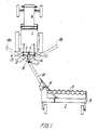
- the driving effect to the driven working means, in casu the rotor disc beam 8 of the cutter 2 is transferred hydrostatically by means of a hydraulic pump 3 releasably connected with the mechanical power take-off 4 of the tractor 1 across a connecting shaft 5 having universal joints 6 and from which a flexible hose connection 7 is established to and along a drawbar 18 to a hydraulic motor 20 accommodated within cutter 2 in driving connection with its rotor disc beam 8.
- the suction of hydraulic liquid, e.g. oil, to the pump 3 is effected from a container not shown which may be disposed on the supporting frame of the agricultural implement 2 across a suction pipe with comparatively large diameter in order to reduce the pressure as much as possible.
- a container not shown which may be disposed on the supporting frame of the agricultural implement 2 across a suction pipe with comparatively large diameter in order to reduce the pressure as much as possible.
- the towing force to the cutter 2 is transferred from the lift arms 9 and 10 of the tractor 1 across a towing device 12 through a coupling joint 17 to the drawbar 18 and further on to the cutter 2 across a coupling joint 19.
- the lift arms 9 and 10 are at their opposite free ends provided with a swivel link in which the towing device 12 may be releasably mounted by means of bearing pins 13.
- the towing device 12 includes a supporting stirrup 14 which in the illustrated embodiment is designed as an upwardly curving, substantially semi-circular tubing provided at its ends with said bearing pins 13 and approximately centrally thereof with a bearing 15 the form of which is more specifically illustrated in Fig, 6, Besides the supporting stirrup 14 the towing device 12 comprises a short connecting rod 16 slopingly directed to the rear and upwards and which at its one end is pivotally coupled to the bearing 15 and at its other end is pivotally connected with the pull rod 18 through a bearing 17.
- the short connecting rod 16 is at its ends provided with bearing yokes 21 and 22, resp., forming angles u and v with the connecting rod 16 as illustrated in Fig. 5, the total angle reaching approximately 90°.
- the bearing 15 has a substantially horizontal pivot axis parallel to the lift arms 9 and 10 and the bearing 17 has a substantially vertical pivot axis while the bearing 13 has a substantially horizontal pivot axis perpendicular to the pivot axes of the bearings 15 and 17.
- a very large area of variation for the angle of the drawbar 18 in the horizontal plane in relation to the longitudinal axis of the tractor 1 is obtained due to the location of the bearing 17 at some distance behind the free ends of the lift arms 9 and 10, said area of variation extending between the illustrated dotted marginal positions 18a and 18b of the pull rod 18.
- the theoretical area of variation is in the illustrated example about ⁇ 120°. This provides for obtaining a very little turning radius, thereby rationalizing and facilitating working in field.
- the hydraulic pump 3 is secured to a mounting plate 23 connected with the supporting stirrup 14 and the area of angular variations of the pivoting movement of the supporting stirrup 14 about the axis of rotation of the bearings 13 will therefore be determined by the universal joints 6 of the connecting shaft 5 across which the input shaft of the hydraulic pump 3 is connected with the power take-off 4 of the tractor 1.
- the pivotal connection in bearings 13 and 15 thus ensures a reasonable manoeuvring ability also in case of sloping and undulating ground.
- the rod 18 may as illustrated in Figs. 2 and 3 be embodied as a hollow profile for interior protected passage of the hose connection 7 between an inlet opening 24 and an outlet opening 25 so that the hose connection 7 is only cleared in the area between the bearing 15 and the coupling joint 17 and around the coupling joint 19 where a flexible motive power transfer is required.
- the hose connection 7 is passed from the outlet opening 25 directly to the hydraulic motor 20 coupled to the rotor disc beam 8.
- FIG. 8 shows a side view of the rearmost part of a tractor 27 with one rear wheel 28 and with a central towing yoke 29 to which the towing device is coupled.
- the towing device 30 includes a sleeve 37 to be rigidly but releasably connected with the towing yoke 29 of the tractor.
- the position of the sleeve 37 may be adjusted in relation to the remaining towing device 30 by means of a telescopically operating adjuster 38.
- the towing device 30 further accommodates a linkage in the form of a spherical joint 34 for pivotal connection with the drawbar 33 that is again connected with a wheeled agricultural implement not illustrated.
- a hydraulic pump 31 is by means of a mounting fixture 40 secured to the towing device 30 so that their mutual positions may be adjusted by means of an adjuster 39.
- the hydraulic pump 31 may by means of the adjusters 38 and 39 be secured relative to the towing device 30 in such a manner that the drive shaft 35 of the hydraulic pump 31 is approximately in alignment with the power take-off part 32 of the tractor 27 and at a certain distance therefrom. This offers the hydraulic pump 31 to be easily and reliably coupled in a releasable manner to the power take-off 32 of the tractor 27 by means of a simple, short propeller shaft 41.
- the motive power is transferred further from the hydraulic pump 31 to the implement across a pivotal hose connection 36 allowing a wide-ranging pivoting between the towing device 30 and the drawbar 33 in the coupling joint 34.
- the drawbar 33 is provided with an adjustable base plate 42 able to settle which under parking retains the implement in the parking position. During coupling and uncoupling the base plate 42 likewise transfers part of the weight of the coupling device to the base, thereby materially facilitating such work.
- Fig. 9 illustrates an embodiment in which the hydraulic pump 43 is completely integral with the container 44 and connected therewith across a very short suction pipe 45.
- the container 44 is secured directly to the towing device, e.g. between the lift arms of a transversal stirrup 46, the end of said lift arms being adapted to be connected with the lift arms 47 of the tractor.
- the releasable mechanical drive connection of the pump 43 with the power take-off 48 is, as in the embodiment in Figs 1 to 7, established across a short connecting shaft 49 with two universal joints 50.
- the hydraulic liquid is fed from the pump 43 through a flexible pressure hose 53 to the hydraulic motor, not shown, from which the liquid is fed back to the container 44 through a return hose 54 that may be carried out with a substantially smaller diameter than a suction hose, the hydraulic liquid being still under pressure in said back-feed pipe.
- a suction hose is made entirely superfluous and the connecting shaft 49a may be very short with a single universal joint 50a.
Abstract
Description
- This invention relates to a coupling device for connecting a wheeled agricultural implement with hydraulically driven working means and a tractor provided with mechanical power take-off comprising a towing device with a coupling joint for pivotal connection with the one end of a drawbar which at its other end is pivotally connected with the implement, and having a motive power transfer from a hydraulic pump mechanically connected with the power take-off of the tractor to the working means of the implement by means of flexible hoses allowing a wide-ranging pivoting of the drawbar in the coupling joint.
- For the connection of such wheeled agricultural implements, inter alia cutters, exact cutters and the like, to a tractor, coupling devices are required which, on one hand, ensure a stable towing connection and, on the other hand, a transfer of motive power from the power take-off of the tractor to the driven working means of the implement in such a manner that the losses of transfer become as small as possible and the manoeuvring ability in field as optimum as possible so that the implement may follow the ground and the crop, thereby running through the field as rationally and quickly as possible.
- In most of the prior coupling systems either the centrally mounted towing hitch of the tractor or a towing bar between the lifting linkage is used for directly coupling the drawbar of the implement through which the towing force is transferred to the implement. The driving power is simultaneously transferred from the power take-off of the tractor by means of a primary, releasable power transfer shaftto a secondary power transfer shaft journalled in connection with the drawbar and connected with the working means of the implement through a universal joint. The primary, releasable power transfer shaft provided with two universal joints and an intermediate telescopic part is a critical point of the coupling-up. To obtain the optimum degree of efficiency and correct geometry of rotation of said shaft the coupling point between the towing device of the tractor and the drawbar must be located approximately halfway between the power take-off of the tractor and the secondary power intake of the power transfer shaft which generally includes a connecting shaft, Since a large angle of swing is at the same time desired when turning in the field, the primary power transfer shaft has to be comparatively long which gives rise to vibrations and thus to increasing wear and tear and even to damage. If the coupling point is moved from the centre of the power transfer shaft, the power transfer shaft may, for the same angle of swing, be shorter. In return, however, the maximum angular motion within the universal joints increases, whereby also wear and tear and the risk of damage increases. This problem may partly be eliminated by use of a so- called wide-angle universal joint, but this solution is still insufficient if it is desired to manoeuvre at large angles of swing.
- With a view to improve the manoeuvring ability and to simultaneously reduce wear and tear in the power transfer a coupling device is known from European patent specification 27295, according to which the towing force as well as the motive power is transferred from the tractor to the implement through a supporting unit for a mechanical transmission consisting of at least two parts mutually pivotal about a vertically extending axis, The one part of said supporting unit operates as a releasable pull connection with the tractor lifting linkage and as a journal for the input shaft of the transmission, respectively, said shaft being releasably connected to the power take-off of the tractor by means of a propeller shaft. The other part of the supporting unit operates as a permanent pull connection with the drawbar of the implement and as a direct or indirect journal bearing forthe output shaft of the transmission, respectively, firmly connected with a mechanical transmission jour- nailed within or along the drawbar and being in the form of a driving shaft or a belt drive transferring the motive power to the working means of the implement.
- Said prior coupling device allows for working at large angles of swing between the tractor and the drawbar of the implement without the risk of overloading the primary power transfer shaft. On the other hand, said solution is more complicated and somewhat more expensive than said conventional solution. Moreover, the flexibility in the feed-back to the tractor is obtained to the detriment of essentially reduced margin with a view to designing the drawbar and the implement proper. In view of the fact that the motive power is transferred further to the implement through a mechanical transmission suspended within or along the drawbar, and as the motive power is transferred therefrom to the implement proper through a drive shaft journalled concentrically with the substantially vertical pivot axis for the connection of the drawbar with the implement proper, the power intake constituted by said shaft is vertically positioned and firmly connected with the drawbar as well as with the main frame of the implement proper. Said circumstance makes it in particular difficult to obtain a simple, reliable and economic structure of the implement with the working means carried out as a separate and relatively light unit that is suspended and can float within the main frame. This is frequently desired with a view to ensure that the working means effectively follow irregularities in the ground and at the same time are damaged as little as possible by collision with solid hindrances such as large stones or the like.
- In order to obtain the same flexibility of the coupling-up between the tractor and the implement as of the coupling device according to the above mentioned patent specification EP-A-27295 it is known from US-A-2569507 to make use of a hydraulic transfer of power, a hydraulic pump being directly mounted on the mechanical power take-off of the tractor wherefrom a flexible hose connection is provided along the drawbar of the implement to a hydraulic motor coupled to the working means of the implement. This provides further for obtaining considerably more independence with respect to the design of the draw bar and the implement proper.
- The connecting joint between the drawbar and the implement proper may thus be placed in the position most advantageous with a view to manoeuvring, straight in front of the field of operation of the working means, without requiring a further transmission connection - as is the case with implements having mechanical transmission. Without causing difficulties with the transmission, the implement may further be provided with separate, floatingly suspended working means possessing the above specified advantages.
- In the known coupling device with hydraulic transmission said flexibility of the connection between the tractor and the implement is further provided in that the drawbar of the implement is connected with the central towing hitch of the tractor across a particular pull extension so that the drawbar is pivotally connected with the pull extension secured to the tractor at a point located behind the rearmost vertical tangential plane of the tractor.
- This solution makes, however, the connection and disconnection of the implement more difficult in that the pull extension must be mounted and dismounted separately if the tractor shall now and then be used together with other towed implements. Moreover, the yoke pull may vary somewhat from one tractor make to another which might necessitate an individual adaptation to the actual tractor type, The coupling and uncoupling is, however, made particularly difficult because the hydraulic pump that is comparatively heavy and connected with strong hoses shall be lifted between a parking fixture on the drawbar and the power take-off shaft of the tractor which during operation both supports and drives the pump. Consequently, the coupling and the uncoupling also includes mounting and dismounting of special fixtures preventing the pump from rotation or being released during working.
- The most essential drawback of the prior coupling device with hydraulic transmission is, however, that it cannot be used in connection with agricultural implements having a high power requirement and which have become continuously more important, since it is not possible to mount the large and heavy pumps necessary for that purpose directly on the power take-off shaft of the tractor without involving unacceptably hard wear and tear and the risk of damage during operation.
- It is the object of the invention to provide a coupling device of the type concerned which is applicable in connection with agricultural implements with a high power requirement and which implies a comparatively simple coupling and uncoupling process and at the same time offers the greatest possible ability of manoeuvring in field and ensures the widest possible independence with respect to the structure of the implement.
- According to the present invention there is provided a coupling device for connecting a wheeled agricultural implement having hydraulically driven working means with a tractor provided with mechanical power take-off comprising a towing device with a coupling joint for permanent pivotal connection with the one end of a drawbar to allow the drawbar to pivot freely at least about an approximately vertical axis, the drawbar being pivotally connected at its other end with the implement, the towing device being adapted to be rigidly but releasably connected with the ordinary towing means of the tractor in such a manner that the coupling joint is located behind the rearmost point of the tractor, characterised by a motive power transfer from a hydraulic pump mechanically connected with the power take-off of the tractor to the working means of the implement by means of flexible hoses allowing a wide ranging pivoting of the drawbar in the coupling joint, the hydraulic pump being permanently secured to the towing device and being permanently connected with the flexible hoses to a hydraulic motor associated with the working means of the implement while it is adapted to be releasably connected with the power take-off of the tractor.
- In the above manner the pump is now not supported by the power take-off shaft of the tractor and there are therefore no longer relevant limits to the weight and size of the pump. The coupling device may therefore also be applicable in connection with large modern agricultural implements with a heavy demand on power.
- At the same time the coupling and uncoupling of the implement is comparatively easy to carry out. The towing device operating as pull extension remains connected with the drawbar when the implement is not in use. The towing device further operates a support for the pump which then, apart from a simple mounting and dismounting of a relatively light transmission shaft, is coupled and uncoupled with the towing device. The weight of the towing device, the pump etc. may in this respect be transferred to the base through a supporting device mounted on the towing device or the drawbar.
- In addition, the same ability of manoeuvering in field and the same independence with a view to the designing of the implement is attained as in the case with the above mentioned prior coupling device with hydraulic transmission.
- In a comparatively simple embodiment the towing device may include a fixture in the form of a sleeve or the like and adapted to be connected with the central towing yoke of the tractor, and the coupling joint may be constituted by a spherical joint allowing the drawbar to freely pivot about an approximately vertical axis and to a certain extent about an arbitrary, approximately horizontal axis.
- As the central towing yoke may however have unlike form and location on different tractor models, it is thus necessary to provide the towing device with additional means for individual adaptation to the respective tractor models.
- Said problem of adaptation may be avoided by a preferred embodiment of the invention which is characterized in that the towing device includes a supporting stirrup with bearing pins for releasable mounting in the lift arms of the tractor so that the towing device can pivot in relation thereto on an approximately horizontal axis and that the hydraulic pump is permanently secured to the supporting stirrup and adapted to be releasably connected with the power take-off of the tractor by means of a connecting shaft provided with a universal joint allowing pivoting of the hydraulic pump together with the supporting stirrup.
- In view of the fact that the three-point suspension with said lift arms is standardised as regards different tractor models the coupling device is in this preferred embodiment applicable without adaptation to various types of tractors.
- According to said embodiment the coupling joint includes a linkage preferably connected between the supporting stirrup and the drawbar and allowing the drawbar to pivot in relation to the lift arms about a substantially vertical axis and about a horizontal axis extending substantially parallel to the lift arms.
- According to a further suitable embodiment the hydraulic pump may be integral with a container for hydraulic liquid secured to the towing device. The need for making use of a long and heavy suction hose is thus eliminated which in order to minimize pressure losses must have a large diameter, the hydraulic pump being possibly accommodated within the container and coupled to the power take-off of the tractor across a short connecting shaft with a single or double universal joint. At the same time the advantage is obtained that the weight of the comparatively heavy container is assumed by the rear wheels of the tractor and not by the wheels of the implement.
- The invention will be explained in detail in the following with reference to the accompanying drawings, in which
- Figs 1 to 3 illustrate a tractor connected to a wheeled agricultural implement by means of a first embodiment of the coupling device according to the invention, viewed from above, in profile and from behind, respectively,
- Figs 4 and 5 illustrate parts of the coupling device, viewed from in front and in profile on a larger scale,
- Figs 6 and 7 are sectional views of bearing means along the lines VI-VI and VII-VII in Figs 4 and 5, respectively,
- Fig. 8 is a lateral view of a simplified embodiment of the coupling device,
- Fig. 9 is a further, expedient embodiment, and
- Fig. 10 is a modification of the embodiment in Fig. 9.
- The driving effect to the driven working means, in casu the rotor disc beam 8 of the
cutter 2, is transferred hydrostatically by means of ahydraulic pump 3 releasably connected with the mechanical power take-off 4 of thetractor 1 across a connectingshaft 5 having universal joints 6 and from which aflexible hose connection 7 is established to and along adrawbar 18 to ahydraulic motor 20 accommodated withincutter 2 in driving connection with its rotor disc beam 8. - The suction of hydraulic liquid, e.g. oil, to the
pump 3 is effected from a container not shown which may be disposed on the supporting frame of theagricultural implement 2 across a suction pipe with comparatively large diameter in order to reduce the pressure as much as possible. - The towing force to the
cutter 2 is transferred from thelift arms tractor 1 across atowing device 12 through acoupling joint 17 to thedrawbar 18 and further on to thecutter 2 across acoupling joint 19. - The
lift arms towing device 12 may be releasably mounted by means of bearingpins 13. - The
towing device 12 includes a supportingstirrup 14 which in the illustrated embodiment is designed as an upwardly curving, substantially semi-circular tubing provided at its ends with said bearingpins 13 and approximately centrally thereof with abearing 15 the form of which is more specifically illustrated in Fig, 6, Besides the supportingstirrup 14 thetowing device 12 comprises ashort connecting rod 16 slopingly directed to the rear and upwards and which at its one end is pivotally coupled to thebearing 15 and at its other end is pivotally connected with thepull rod 18 through abearing 17. - In order to establish connection with the
bearings rod 16 is at its ends provided withbearing yokes rod 16 as illustrated in Fig. 5, the total angle reaching approximately 90°. - As it will appear from Figs 2, 4 and 5 the
bearing 15 has a substantially horizontal pivot axis parallel to thelift arms bearing 17 has a substantially vertical pivot axis while thebearing 13 has a substantially horizontal pivot axis perpendicular to the pivot axes of thebearings - As it most clearly appears from Fig. 1 a very large area of variation for the angle of the
drawbar 18 in the horizontal plane in relation to the longitudinal axis of thetractor 1 is obtained due to the location of thebearing 17 at some distance behind the free ends of thelift arms pull rod 18. The theoretical area of variation is in the illustrated example about ± 120°. This provides for obtaining a very little turning radius, thereby rationalizing and facilitating working in field. - Also by the
bearing 15 accommodated in the supporting stirrup 14 a considerable area of variation is obtained for the angle in the vertical plane between the connectingrod 16 and thereby thedrawbar 18 and the horizontal line connecting thebearings 13, as illustrated in Fig. 3. - In the illustrated embodiment the
hydraulic pump 3 is secured to amounting plate 23 connected with the supportingstirrup 14 and the area of angular variations of the pivoting movement of the supportingstirrup 14 about the axis of rotation of thebearings 13 will therefore be determined by the universal joints 6 of the connectingshaft 5 across which the input shaft of thehydraulic pump 3 is connected with the power take-off 4 of thetractor 1. The pivotal connection inbearings - The
rod 18 may as illustrated in Figs. 2 and 3 be embodied as a hollow profile for interior protected passage of thehose connection 7 between an inlet opening 24 and an outlet opening 25 so that thehose connection 7 is only cleared in the area between thebearing 15 and thecoupling joint 17 and around thecoupling joint 19 where a flexible motive power transfer is required. - The
hose connection 7 is passed from the outlet opening 25 directly to thehydraulic motor 20 coupled to the rotor disc beam 8. - To illustrate a simplified embodiment of the coupling device according to the invention Fig, 8 shows a side view of the rearmost part of a
tractor 27 with onerear wheel 28 and with acentral towing yoke 29 to which the towing device is coupled. - The towing
device 30 includes asleeve 37 to be rigidly but releasably connected with the towingyoke 29 of the tractor. The position of thesleeve 37 may be adjusted in relation to the remaining towingdevice 30 by means of a telescopically operatingadjuster 38. - The towing
device 30 further accommodates a linkage in the form of a spherical joint 34 for pivotal connection with thedrawbar 33 that is again connected with a wheeled agricultural implement not illustrated. - A
hydraulic pump 31 is by means of a mounting fixture 40 secured to the towingdevice 30 so that their mutual positions may be adjusted by means of anadjuster 39. - The
hydraulic pump 31 may by means of theadjusters device 30 in such a manner that thedrive shaft 35 of thehydraulic pump 31 is approximately in alignment with the power take-offpart 32 of thetractor 27 and at a certain distance therefrom. This offers thehydraulic pump 31 to be easily and reliably coupled in a releasable manner to the power take-off 32 of thetractor 27 by means of a simple, short propeller shaft 41. - The motive power is transferred further from the
hydraulic pump 31 to the implement across apivotal hose connection 36 allowing a wide-ranging pivoting between the towingdevice 30 and thedrawbar 33 in thecoupling joint 34. - In the illustrated embodiment the
drawbar 33 is provided with an adjustable base plate 42 able to settle which under parking retains the implement in the parking position. During coupling and uncoupling the base plate 42 likewise transfers part of the weight of the coupling device to the base, thereby materially facilitating such work. - While hydraulic liquid, e.g. oil, is supplied from a container that may be mounted on the transversal frame of the implement 2, in casu the transversal frame of the cutter, to the
hydraulic pump hydraulic pump 43 is completely integral with thecontainer 44 and connected therewith across a veryshort suction pipe 45. Thecontainer 44 is secured directly to the towing device, e.g. between the lift arms of a transversal stirrup 46, the end of said lift arms being adapted to be connected with thelift arms 47 of the tractor. The releasable mechanical drive connection of thepump 43 with the power take-off 48 is, as in the embodiment in Figs 1 to 7, established across a short connectingshaft 49 with twouniversal joints 50. - By making the hydraulic pump and the container integrally it is avoided, as already explained, having to make use of a long and consequently heavy and clumsy suction pipe for a separate container on the implement and by mounting the
container 44 directly on the towing device at the foremost end of thedrawbar 51 the weight of the container is transferred to therear wheel 52 of the tractor and shall not be supported by the front wheels of the tractor. - The hydraulic liquid is fed from the
pump 43 through aflexible pressure hose 53 to the hydraulic motor, not shown, from which the liquid is fed back to thecontainer 44 through areturn hose 54 that may be carried out with a substantially smaller diameter than a suction hose, the hydraulic liquid being still under pressure in said back-feed pipe. - By disposing the
hydraulic pump 43 within the container 44a, as illustrated in Fig. 10, a suction hose is made entirely superfluous and the connecting shaft 49a may be very short with a singleuniversal joint 50a.
Claims (8)
Applications Claiming Priority (2)
| Application Number | Priority Date | Filing Date | Title |
|---|---|---|---|
| DK241185A DK167043B1 (en) | 1985-05-30 | 1985-05-30 | CLUTCH DEVICE FOR CONNECTING A TRAFFIC MARKET TO A TRACTOR |
| DK2411/85 | 1985-05-30 |
Publications (2)
| Publication Number | Publication Date |
|---|---|
| EP0223801A1 EP0223801A1 (en) | 1987-06-03 |
| EP0223801B1 true EP0223801B1 (en) | 1990-08-01 |
Family
ID=8112192
Family Applications (1)
| Application Number | Title | Priority Date | Filing Date |
|---|---|---|---|
| EP86903271A Expired - Lifetime EP0223801B1 (en) | 1985-05-30 | 1986-05-26 | A coupling device for connecting a wheeled field implement to a tractor |
Country Status (5)
| Country | Link |
|---|---|
| US (1) | US4838358A (en) |
| EP (1) | EP0223801B1 (en) |
| DE (1) | DE3673131D1 (en) |
| DK (1) | DK167043B1 (en) |
| WO (1) | WO1986006927A1 (en) |
Cited By (1)
| Publication number | Priority date | Publication date | Assignee | Title |
|---|---|---|---|---|
| DE29704121U1 (en) * | 1997-03-07 | 1997-05-15 | Rau Gmbh Maschf | Mobile spraying device |
Families Citing this family (19)
| Publication number | Priority date | Publication date | Assignee | Title |
|---|---|---|---|---|
| US5287934A (en) * | 1988-12-02 | 1994-02-22 | Brian Porter | Soil working implement |
| FR2652705B1 (en) * | 1989-10-11 | 1992-03-06 | Lucas Sa G | IMPROVEMENT IN THE TRACTOR HITCHING SYSTEM OF A CENTRAL AXLE TRAILER, AND IN PARTICULAR A REAR LOADING AGRICULTURAL TRAILER. |
| US5335856A (en) * | 1992-10-13 | 1994-08-09 | Fmc Corporation | Air boom sprayer trailer hitch and suspension |
| US6082085A (en) * | 1998-05-13 | 2000-07-04 | Agco Corporation | Foliage mowing implement having mechanical drive with main gearbox rotation |
| CA2274288A1 (en) | 1999-06-09 | 2000-12-09 | Mcleod Harvest Inc. | Method and apparatus for harvesting crops |
| CA2327994A1 (en) | 2000-12-08 | 2002-06-08 | Robert H. Mcleod | Hydraulic drive line for pull-type crop harvester |
| CA2332684C (en) * | 2000-12-08 | 2005-04-12 | Mcleod Harvest Inc. | Hydraulic drive line and hitching assembly for pull-type implements |
| US6966388B1 (en) * | 2004-06-07 | 2005-11-22 | Cnh America Llc | Offset hitch |
| CA2538020C (en) * | 2006-02-24 | 2012-08-21 | Macdon Industries Ltd. | Hydraulic drive arrangement for the cutter of a pull-type crop harvesting machine |
| CA2538489C (en) * | 2006-02-24 | 2012-01-31 | Macdon Industries Ltd. | Connection of the hitch arm of a pull-type machine to a tractor |
| NL1036352C2 (en) * | 2008-12-22 | 2010-06-23 | Lely Patent Nv | TOPHEF COUPLING. |
| NL1037742C2 (en) * | 2010-02-23 | 2011-08-24 | Forage Innovations Bv | Wrapper for wrapping bales of crop material. |
| FR2961721B1 (en) * | 2010-06-28 | 2013-03-08 | Chambre D Agriculture Du Gard | DEVICE FOR CLEANING AGRICULTURAL MACHINE. |
| DE102010041885A1 (en) * | 2010-10-01 | 2012-04-05 | Deere & Company | Combination of a towing vehicle and a device |
| US8096571B1 (en) * | 2010-10-12 | 2012-01-17 | Richard Dale Noe | Tractor hitch assembly and trailer with hydraulic pump |
| ITPD20120330A1 (en) * | 2012-11-06 | 2014-05-07 | Maschio Gaspardo Spa | ATTACHMENT DEVICE FOR TRAILED AGRICULTURAL EQUIPMENT |
| EP3008985B1 (en) * | 2014-10-15 | 2017-08-09 | Kverneland Group Ravenna S.r.l. | Towing apparatus for agricultural machines, of the type of balers, round balers and the like |
| US10231372B2 (en) * | 2017-02-24 | 2019-03-19 | Matthew S. Pennybacker | Coupling device to connect two tractor-pulled agricultural implements for tandem-powered operation |
| US10926969B1 (en) * | 2020-06-05 | 2021-02-23 | James P. Shea | Roller arm assembly for temporary tape removal machine |
Family Cites Families (15)
| Publication number | Priority date | Publication date | Assignee | Title |
|---|---|---|---|---|
| US1496999A (en) * | 1922-04-03 | 1924-06-10 | Charles H Ray | Tractor harvester transmission |
| US1661737A (en) * | 1925-08-17 | 1928-03-06 | Raimer Philip | Tractor trailer connection |
| US2171761A (en) * | 1937-06-04 | 1939-09-05 | Deere & Co | Mower |
| US2569507A (en) * | 1945-10-27 | 1951-10-02 | Schlegell Frederick Von | Hydraulic operating system for mowing machines |
| GB828029A (en) * | 1956-10-23 | 1960-02-10 | Aage Moustgaard | Improvements in mechanical transmission means for transmitting torque from the power take off shaft of a tractor |
| FR1187344A (en) * | 1957-11-29 | 1959-09-09 | Attachment and transmission device between a tractor and a combine harvester | |
| NL6503955A (en) * | 1965-03-29 | 1966-09-30 | ||
| FR1563090A (en) * | 1968-02-23 | 1969-04-11 | ||
| US3665685A (en) * | 1970-07-06 | 1972-05-30 | Jean Allard | Mowing device for cutting vegetation adjacent a fence |
| GB1379601A (en) * | 1971-03-01 | 1975-01-02 | Mccormack P D | Apparatus for cleaning and trimming back verges of unkerbed roads |
| US3715872A (en) * | 1971-07-19 | 1973-02-13 | P Thompson | Mowing apparatus |
| BE792147A (en) * | 1971-12-03 | 1973-03-16 | Mulag Fahrzeug Woessner | VACUUM MOWING MACHINE |
| NL7907546A (en) * | 1979-10-11 | 1981-04-14 | Multinorm Bv | POWER-TRANSMITTING COUPLING DEVICE ON A TRACTOR AND IMPLEMENT ATTACHED TO IT. |
| EP0090879A1 (en) * | 1982-01-21 | 1983-10-12 | B. Strautmann & Söhne GmbH & Co. | Hydraulic transmission system for an agricultural implement |
| US4584826A (en) * | 1983-02-23 | 1986-04-29 | Blackwelders | Tomato harvester |
-
1985
- 1985-05-30 DK DK241185A patent/DK167043B1/en not_active IP Right Cessation
-
1986
- 1986-05-26 EP EP86903271A patent/EP0223801B1/en not_active Expired - Lifetime
- 1986-05-26 WO PCT/DK1986/000057 patent/WO1986006927A1/en active IP Right Grant
- 1986-05-26 US US07/014,065 patent/US4838358A/en not_active Expired - Fee Related
- 1986-05-26 DE DE8686903271T patent/DE3673131D1/en not_active Expired - Fee Related
Cited By (1)
| Publication number | Priority date | Publication date | Assignee | Title |
|---|---|---|---|---|
| DE29704121U1 (en) * | 1997-03-07 | 1997-05-15 | Rau Gmbh Maschf | Mobile spraying device |
Also Published As
| Publication number | Publication date |
|---|---|
| DK241185D0 (en) | 1985-05-30 |
| US4838358A (en) | 1989-06-13 |
| DK167043B1 (en) | 1993-08-23 |
| WO1986006927A1 (en) | 1986-12-04 |
| DE3673131D1 (en) | 1990-09-06 |
| DK241185A (en) | 1986-12-01 |
| EP0223801A1 (en) | 1987-06-03 |
Similar Documents
| Publication | Publication Date | Title |
|---|---|---|
| EP0223801B1 (en) | A coupling device for connecting a wheeled field implement to a tractor | |
| EP1825736B1 (en) | Connection of the hitch arm of a pull-type crop harvesting machine to a tractor | |
| US4899523A (en) | Mower | |
| US5094063A (en) | Mower including a group of working elements extending crosswise to a direction of advance at work | |
| US4719742A (en) | Mowing machine | |
| US5355971A (en) | Drivetrain and load bearing swivel hitch assembly and combine incorporating same | |
| US4330981A (en) | Towable ganged mower | |
| US5901533A (en) | Agricultural machine | |
| EP2055169A2 (en) | Drive system for an agricultural machine with a floating work tool | |
| US5473872A (en) | Angled drive for an agriculural header assembly | |
| US20040070172A1 (en) | Offset arm for towing rotary mowers and the like | |
| EP1347676B1 (en) | Hydraulic drive line and hitching assembly for pull-type implement | |
| US6003291A (en) | Agriculture machine | |
| CA2465937C (en) | Articulated power transfer apparatus | |
| US11116124B2 (en) | Implement offset arm | |
| US4648472A (en) | Tractor for agricultural purposes | |
| US4570425A (en) | Hydraulically operated gang mower trailer | |
| US5265403A (en) | Draft tongue for connecting PTO-driven implement to draft links of a towing vehicle | |
| US6129372A (en) | Self-propelled agricultural implement | |
| US10231372B2 (en) | Coupling device to connect two tractor-pulled agricultural implements for tandem-powered operation | |
| US20210168990A1 (en) | Articulated implement towing apparatus | |
| US2744374A (en) | Reciprocating cutting assembly with tractor mountable hitch structure | |
| US6464016B2 (en) | Hitch system | |
| CA2136498C (en) | Angled drive for an agricultural header assembly | |
| EP0006302A1 (en) | Vehicle with hydraulic drive means |
Legal Events
| Date | Code | Title | Description |
|---|---|---|---|
| PUAI | Public reference made under article 153(3) epc to a published international application that has entered the european phase |
Free format text: ORIGINAL CODE: 0009012 |
|
| 17P | Request for examination filed |
Effective date: 19870218 |
|
| AK | Designated contracting states |
Kind code of ref document: A1 Designated state(s): BE CH DE FR GB LI NL |
|
| 17Q | First examination report despatched |
Effective date: 19880308 |
|
| GRAA | (expected) grant |
Free format text: ORIGINAL CODE: 0009210 |
|
| AK | Designated contracting states |
Kind code of ref document: B1 Designated state(s): BE CH DE FR GB LI NL |
|
| PG25 | Lapsed in a contracting state [announced via postgrant information from national office to epo] |
Ref country code: LI Effective date: 19900801 Ref country code: CH Effective date: 19900801 Ref country code: BE Effective date: 19900801 |
|
| REF | Corresponds to: |
Ref document number: 3673131 Country of ref document: DE Date of ref document: 19900906 |
|
| ET | Fr: translation filed | ||
| REG | Reference to a national code |
Ref country code: CH Ref legal event code: PL |
|
| PLBE | No opposition filed within time limit |
Free format text: ORIGINAL CODE: 0009261 |
|
| STAA | Information on the status of an ep patent application or granted ep patent |
Free format text: STATUS: NO OPPOSITION FILED WITHIN TIME LIMIT |
|
| 26N | No opposition filed | ||
| PGFP | Annual fee paid to national office [announced via postgrant information from national office to epo] |
Ref country code: GB Payment date: 19990513 Year of fee payment: 14 |
|
| PGFP | Annual fee paid to national office [announced via postgrant information from national office to epo] |
Ref country code: FR Payment date: 19990521 Year of fee payment: 14 |
|
| PGFP | Annual fee paid to national office [announced via postgrant information from national office to epo] |
Ref country code: NL Payment date: 19990531 Year of fee payment: 14 |
|
| PGFP | Annual fee paid to national office [announced via postgrant information from national office to epo] |
Ref country code: DE Payment date: 19990721 Year of fee payment: 14 |
|
| PG25 | Lapsed in a contracting state [announced via postgrant information from national office to epo] |
Ref country code: GB Free format text: LAPSE BECAUSE OF NON-PAYMENT OF DUE FEES Effective date: 20000526 |
|
| PG25 | Lapsed in a contracting state [announced via postgrant information from national office to epo] |
Ref country code: NL Free format text: LAPSE BECAUSE OF NON-PAYMENT OF DUE FEES Effective date: 20001201 |
|
| GBPC | Gb: european patent ceased through non-payment of renewal fee |
Effective date: 20000526 |
|
| PG25 | Lapsed in a contracting state [announced via postgrant information from national office to epo] |
Ref country code: FR Free format text: LAPSE BECAUSE OF NON-PAYMENT OF DUE FEES Effective date: 20010131 |
|
| NLV4 | Nl: lapsed or anulled due to non-payment of the annual fee |
Effective date: 20001201 |
|
| PG25 | Lapsed in a contracting state [announced via postgrant information from national office to epo] |
Ref country code: DE Free format text: LAPSE BECAUSE OF NON-PAYMENT OF DUE FEES Effective date: 20010301 |
|
| REG | Reference to a national code |
Ref country code: FR Ref legal event code: ST |