EP0223427B1 - Method and apparatus for the determination of the antibody content of blood - Google Patents
Method and apparatus for the determination of the antibody content of blood Download PDFInfo
- Publication number
- EP0223427B1 EP0223427B1 EP86308159A EP86308159A EP0223427B1 EP 0223427 B1 EP0223427 B1 EP 0223427B1 EP 86308159 A EP86308159 A EP 86308159A EP 86308159 A EP86308159 A EP 86308159A EP 0223427 B1 EP0223427 B1 EP 0223427B1
- Authority
- EP
- European Patent Office
- Prior art keywords
- sample
- radiation
- light
- intensity
- scattered
- Prior art date
- Legal status (The legal status is an assumption and is not a legal conclusion. Google has not performed a legal analysis and makes no representation as to the accuracy of the status listed.)
- Expired - Lifetime
Links
Images



Classifications
-
- G—PHYSICS
- G01—MEASURING; TESTING
- G01N—INVESTIGATING OR ANALYSING MATERIALS BY DETERMINING THEIR CHEMICAL OR PHYSICAL PROPERTIES
- G01N33/00—Investigating or analysing materials by specific methods not covered by groups G01N1/00 - G01N31/00
- G01N33/48—Biological material, e.g. blood, urine; Haemocytometers
- G01N33/50—Chemical analysis of biological material, e.g. blood, urine; Testing involving biospecific ligand binding methods; Immunological testing
- G01N33/53—Immunoassay; Biospecific binding assay; Materials therefor
-
- G—PHYSICS
- G01—MEASURING; TESTING
- G01N—INVESTIGATING OR ANALYSING MATERIALS BY DETERMINING THEIR CHEMICAL OR PHYSICAL PROPERTIES
- G01N21/00—Investigating or analysing materials by the use of optical means, i.e. using sub-millimetre waves, infrared, visible or ultraviolet light
- G01N21/17—Systems in which incident light is modified in accordance with the properties of the material investigated
- G01N21/47—Scattering, i.e. diffuse reflection
-
- G—PHYSICS
- G01—MEASURING; TESTING
- G01N—INVESTIGATING OR ANALYSING MATERIALS BY DETERMINING THEIR CHEMICAL OR PHYSICAL PROPERTIES
- G01N33/00—Investigating or analysing materials by specific methods not covered by groups G01N1/00 - G01N31/00
- G01N33/48—Biological material, e.g. blood, urine; Haemocytometers
- G01N33/50—Chemical analysis of biological material, e.g. blood, urine; Testing involving biospecific ligand binding methods; Immunological testing
- G01N33/53—Immunoassay; Biospecific binding assay; Materials therefor
- G01N33/557—Immunoassay; Biospecific binding assay; Materials therefor using kinetic measurement, i.e. time rate of progress of an antigen-antibody interaction
-
- G—PHYSICS
- G01—MEASURING; TESTING
- G01N—INVESTIGATING OR ANALYSING MATERIALS BY DETERMINING THEIR CHEMICAL OR PHYSICAL PROPERTIES
- G01N2201/00—Features of devices classified in G01N21/00
- G01N2201/12—Circuits of general importance; Signal processing
- G01N2201/122—Kinetic analysis; determining reaction rate
-
- Y—GENERAL TAGGING OF NEW TECHNOLOGICAL DEVELOPMENTS; GENERAL TAGGING OF CROSS-SECTIONAL TECHNOLOGIES SPANNING OVER SEVERAL SECTIONS OF THE IPC; TECHNICAL SUBJECTS COVERED BY FORMER USPC CROSS-REFERENCE ART COLLECTIONS [XRACs] AND DIGESTS
- Y10—TECHNICAL SUBJECTS COVERED BY FORMER USPC
- Y10S—TECHNICAL SUBJECTS COVERED BY FORMER USPC CROSS-REFERENCE ART COLLECTIONS [XRACs] AND DIGESTS
- Y10S436/00—Chemistry: analytical and immunological testing
- Y10S436/805—Optical property
-
- Y—GENERAL TAGGING OF NEW TECHNOLOGICAL DEVELOPMENTS; GENERAL TAGGING OF CROSS-SECTIONAL TECHNOLOGIES SPANNING OVER SEVERAL SECTIONS OF THE IPC; TECHNICAL SUBJECTS COVERED BY FORMER USPC CROSS-REFERENCE ART COLLECTIONS [XRACs] AND DIGESTS
- Y10—TECHNICAL SUBJECTS COVERED BY FORMER USPC
- Y10S—TECHNICAL SUBJECTS COVERED BY FORMER USPC CROSS-REFERENCE ART COLLECTIONS [XRACs] AND DIGESTS
- Y10S436/00—Chemistry: analytical and immunological testing
- Y10S436/825—Pretreatment for removal of interfering factors from sample
-
- Y—GENERAL TAGGING OF NEW TECHNOLOGICAL DEVELOPMENTS; GENERAL TAGGING OF CROSS-SECTIONAL TECHNOLOGIES SPANNING OVER SEVERAL SECTIONS OF THE IPC; TECHNICAL SUBJECTS COVERED BY FORMER USPC CROSS-REFERENCE ART COLLECTIONS [XRACs] AND DIGESTS
- Y10—TECHNICAL SUBJECTS COVERED BY FORMER USPC
- Y10S—TECHNICAL SUBJECTS COVERED BY FORMER USPC CROSS-REFERENCE ART COLLECTIONS [XRACs] AND DIGESTS
- Y10S436/00—Chemistry: analytical and immunological testing
- Y10S436/909—Nephelometry
Definitions
- the present invention relates to a method of determining the content of a component in a sample of blood, particularly the antigen or antibody content of a sample of whole blood.
- a flash light source such as a xenon flash (DE-A-3020677) in a nephelometer
- a flash light source such as a xenon flash (DE-A-3020677)
- DE-A-3020677 xenon flash
- the previously proposed designs of nephelometer suffer from the problems that they are intended for use with existing methods of blood analysis and consequently utilize wavelengths of radiation which either require stabilized power supplies, e.g. ultra violet wavelengths, or wavelengths which would be absorbed by haemoglobin and so require separation of red blood cells or haemoglobin from a blood sample if they are to be useful.
- a method of quantifying, in a whole blood sample in which the red cells have been lysed, a molecular component which will react with a reagent to form an antigen-antibody complex comprising the steps of mixing said sample with said reagent to form said complex, exposing said sample to a source of light radiation and measuring the intensity of radiation scattered through a given angle by said complex, the wavelength of the radiation being such that the ratio of the intensity of detected scattered radiation to that of radiation absorbed by haemoglobin from said lysed red cells is maximised, and the intensity of light transmitted through said sample being detected and used to modify the levels of detected scattered light, so that measurements derived therefrom substantially correspond to the levels of said antigen-antibody complex.
- the invention also resides in an apparatus for performing the above method.
- the intensity of said scattered radiation is measured at intervals, to determine the rate of formation of said antigen-antibody complex.
- the wavelength of the radiation is selected such that it is a wavelength at which the intensity of the radiation scattered through said angle by the antigen/antibody complex is high and the absorption of said radiation by haemoglobin and other proteins is low. It is particularly preferred that the intensity of the scattered radiation is at a local maximum and the absorption of the radiation is at a local minimum.
- Typical wavelengths of suitable radiation are 460-530 nm, more preferably 460-510 nm.
- the red cells are lysed such that they fragment into particles of a size which does not scatter light of these wavelengths and so reduces interference.
- an apparatus for use in the method of the invention comprising means for receiving said sample and said reagent, a light source for illuminating said sample, and devices for detecting the intensity of light scattered at a predetermined angle by said sample, and for quantifying said component from said detected intensity, characterised in that said light has a wavelength such that the ratio of the intensity of detected scattered radiation to that of radiation absorbed by the haemoglobin from said lysed red cells is maximised, and in that said apparatus includes a device for detecting the intensity of light transmitted through said sample and a circuit for modifying the levels of detected scattered light so that measurements derived therefrom substantially correspond to the levels of said antigen-antibody complex.
- the apparatus is portable and it is also preferred that the radiation source is a xenon flash tube powered by a dry cell battery.
- the duration of the flash may be controlled automatically by means of a sensor which monitors the amount of light reflected or transmitted by the sample and which is connected to the source to terminate the flash when sufficient light has been reflected. More particularly, the amount of haemoglobin in the sample is measured by measuring the light transmitted by the sample at a wavelength corresponding to a haemoglobin absorption peak and this measurement is used to control the duration of the flash and so compensate for the red blood cell content of the sample.
- the apparatus comprises a high intensity light source comprising a xenon flash discharge tube 10, such as is typically used in photography powered by a small dry cell.
- a xenon flash discharge tube 10 such as is typically used in photography powered by a small dry cell.
- This tube in conjunction with interference filters and suitable attenuation means 11, 12, gives a narrow band width source of radiation with a maximum at 479 nm.
- the filters are desired to give a maximum at 473 nm but production defects may cause a small shift of a few nm from this from filter to filter.
- a high intensity output light emitting diode can be used. This has the advantage that the wavelength of the emitted light (e.g.480 nm) can be controlled quite accurately and so reduces the need for extensive filtering.
- a cuvette 13 is charged with 3.0 ml of physiological saline/4 percent polyethylene glycol, 20 ⁇ l of Zaponin®/KCN, which is a trademark, and is available from Ortho Pharmaceutical and 5 ⁇ l of whole blood. 40 ⁇ l of anti IgG antiserum is added to this mixture. It is possible to increase the sensitivity of the method according to the present invention by using particle bound antibodies e.g latex bound antibodies which cause agglomerates to form which scatter radiation more effectively.
- particle bound antibodies e.g latex bound antibodies which cause agglomerates to form which scatter radiation more effectively.
- the cuvette 13 is made from a suitable transparent material and is placed in the path of the light 16 from the flash tube 10. Because it is not necessary to effect any pre-treatment to the blood sample before it is introduced into the cuvette, it is possible to reduce the amount of handling of the sample to a minimum. This reduces any contact the operator may have with the blood sample to a minimum and so increases the safety of the present method and apparatus.
- a photo diode detector 14 is arranged to receive any light 17 which is scattered through a given angle from the sample, in the present case the angle is 90°.
- the interference filters 11 are placed between the flash tube 10 and the detector 14 such that only light of a specified wavelength is transmitted to the detector 14.
- a further detector 15 is positioned to detect light 18 transmitted by the sample at a given wavelength (selected by means of futher filters 20) corresponding to haemoglobin absorption. This detector 15 is linked via control circuitry 19 to the flash tube 10 and terminates the flash when sufficient light has been received. This automatically compensates for the red blood cell content of the sample.
- the wavelength of light used is chosen such that the signal from the complex is relatively high and the signal from haemoglobin is at a relative minimum (x) and the total signal relative to background signal is as strong as possible. This is done to ensure that the strength of the signal obtained is mainly effected by the concentration of the complex rather than other incidental factors.
- the wavelength chosen is 473 nm ( ⁇ a few nm due to variations between filters).
- the detector 14 is linked to a calibrated display 21 such that the signal may be directly displayed in terms of antigen concentration.
- Fig. 5 those parts which are the same as shown in Fig. 4 are given the same reference numerals in the 100 series.
- flash charge and trigger circuitry located within a screened compartment 126 controlling activation of the xenon discharge tube 110, said tube 110, interference filter and illumination aperture 111 and 112, the sample 113, a light sink 127 and the detector 114 in a scatter aperture pipe 128.
- the light sink 127 serves to absorb any light which is transmitted by the sample and so prevent any reflections within the chamber 125 which may affect the readings.
- the detector 114 and aperture pipe 128 are arranged in such a way that only light which has been scattered through substantially 90° falls upon the detector 114.
- the detector 114 emits a signal to a detector amplifier 129 which has means 130 for adjusting the gain on the amplifier 129 and hence allows adjustment of the sensitivity of the apparatus.
- a signal from the amplifier 129 is taken to a peak detector 131 which is connected to a timing circuit 132 provided with adjustment means 133.
- the timing circuit is also connected to the trigger circuitry in compartment 126.
- the timing circuit 132 controls the activation of the tube 110 and the peak detector 131. Activation of the timing circuits 132 causes the tube to discharge at a given time after the immunochemical reaction has been initiated in the cuvette 113.
- the peak detector 131 is activated a short time after the tube 110 is discharged in order to eliminate any e.m.f. peak effects caused by the discharge.
- the peak detector 131 continues to function until a peak is reached when no more readings are taken.
- the signal from the peak detector 131 is fed into a digital multimeter 134 which is provided with controls for zeroing 135 and calibration 136. The readings from the multimeter are shown on a digital display 121.
- This apparatus does not cater for compensation for differences between test blanks or in differences in haemoglobin level between samples, and is not therefore exemplary of the invention, but merely shows timing and calibration controls included in the embodiments of Figures 6 and 7.
- Activation of the timing circuits 132 may be achieved manually by operating a switch when the cuvette 113 has been inserted, or insertion of the cuvette 113 can cause automatic operation by use of a micro-switch.
- the interference filter 211 is located between the cuvette 213 and the detector 214.
- a further interference filter 220 is located between the cuvette 213 and the light sink 227.
- a transmission aperture pipe 240 having a further detector 241 therein is provided in the light sink 227 and is arranged to receive light which has been transmitted through the sample.
- the signal from the further detector 241 is passed to an associated amplifier 242 which in turn sends a signal to the flash change and trigger circuitry. This arrangement is used to control the duration of the flash in order to compensate for the amount of light absorbed by the haemoglobin in the sample.
- the signal from the detector 214 is fed to a peak detector 231 via an amplifier 229 as before, the peak detector being controlled by timing circuitry 232.
- the output from the peak detector is fed through a two-way switch 243 to either a first sample and hold circuit 244 or a second sample and hold circuit 245.
- Both sample and hold circuits 244, 245 and the switch 243 are controlled by the timing circuits 232.
- the output of the sample and hold circuits 244, 245 is fed to a digital multimeter 234 with calibration control 236 and displayed on a digital display 221.
- a first reading is taken when the immunological reaction is initiated and the switch 243 is operated by the circuit 232 such that the output from the peak detector 231 is fed to the first sample and hold circuits 244.
- a second reading is taken and is fed to the second sample and hold circuits 245.
- the output from the first sample and hold circuits is fed to a zero reference pin on the multimeter 234 and so the output from the second sample and hold circuits 245 can be displayed to give the change in scatter intensity after said pre-set time interval, the zero reading being used to compensate for any scatter from the sample which is not due to the immunological reaction.
- Fig. 7 parts corresponding to these parts shown in previous drawings are given the same reference numerals in the 300 series.
- the apparatus shown in Fig. 7 is controlled by a micro computer which handles timing control and data analysis operations.
- an incident light detector 353 is included to measure the incident light from the tube 310. This can be used to improve the accuracy of the apparatus.
- the output from each detector 314, 341, 353 is fed to an associated amplifier 329, 342, 350 and then to a respective peak detector 331a, 331b, 331c.
- the output from each peak detector 331a, 33ab, 331c is fed to a multiplexer 354 and then to an analogue to digital converter 355 which is connected to a micro computer 356.
- the micro computer 356 replaces the timing circuits shown in previous embodiments and also controls sample processor 357 which can process the sample accurately before the readings are taken and so improve overall accuracy.
- a rate determining method When there is high interference to the signal from the complex due to other proteins, it is preferable to use a rate determining method. In this case, measurements are taken at specific time intervals after the blood sample and the antigen are mixed. Typically, a number of readings over a few seconds and the detected signals are fed to data analysis means which allows determination of the rate of formation of the antigen/antibody complex and hence the concentration of the antibody.
Landscapes
- Health & Medical Sciences (AREA)
- Life Sciences & Earth Sciences (AREA)
- Immunology (AREA)
- Engineering & Computer Science (AREA)
- Chemical & Material Sciences (AREA)
- Hematology (AREA)
- Urology & Nephrology (AREA)
- Molecular Biology (AREA)
- Biomedical Technology (AREA)
- General Health & Medical Sciences (AREA)
- Pathology (AREA)
- General Physics & Mathematics (AREA)
- Physics & Mathematics (AREA)
- Biochemistry (AREA)
- Analytical Chemistry (AREA)
- Biotechnology (AREA)
- Microbiology (AREA)
- Cell Biology (AREA)
- Food Science & Technology (AREA)
- Medicinal Chemistry (AREA)
- Chemical Kinetics & Catalysis (AREA)
- Investigating Or Analysing Materials By Optical Means (AREA)
- Investigating Or Analysing Biological Materials (AREA)
- Peptides Or Proteins (AREA)
Abstract
Description
- The present invention relates to a method of determining the content of a component in a sample of blood, particularly the antigen or antibody content of a sample of whole blood.
- It is known, for example from EP-A-0091636, to quantify components in a sample of blood by forming a complex between the component and marker antibodies to form agglomerates. These agglomerates will scatter incident radiation and by measuring the intensity of the scattered radiation, the concentration of complex agglomerates, and hence the concentration of antigen can be determined.
- However, since both haemoglobin, and red blood cells also absorb and scatter radiation it has been considered necessary to remove the red blood cells by centrifuging. Such a procedure is time consuming and requires the immediate availability of centrifuging equipment. Though this problem may be reduced by the use of radiation in the ultra-violet part of the spectrum, this requires mains electricity and a bulky power unit.
- It has been proposed to utilize a flash light source such as a xenon flash (DE-A-3020677) in a nephelometer, in order to increase the intensity of the incident light and thereby to obtain satisfactory readings of turbidity levels which would otherwise be too low to detect. However, the previously proposed designs of nephelometer suffer from the problems that they are intended for use with existing methods of blood analysis and consequently utilize wavelengths of radiation which either require stabilized power supplies, e.g. ultra violet wavelengths, or wavelengths which would be absorbed by haemoglobin and so require separation of red blood cells or haemoglobin from a blood sample if they are to be useful.
- It is an object of the present invention to provide a method and an apparatus (nephelometer) which can be used to analyse samples of whole blood without the need to remove red blood cells or haemoglobin.
- According to the invention there is provided a method of quantifying, in a whole blood sample in which the red cells have been lysed, a molecular component which will react with a reagent to form an antigen-antibody complex, said method comprising the steps of mixing said sample with said reagent to form said complex, exposing said sample to a source of light radiation and measuring the intensity of radiation scattered through a given angle by said complex, the wavelength of the radiation being such that the ratio of the intensity of detected scattered radiation to that of radiation absorbed by haemoglobin from said lysed red cells is maximised, and the intensity of light transmitted through said sample being detected and used to modify the levels of detected scattered light, so that measurements derived therefrom substantially correspond to the levels of said antigen-antibody complex.
- The invention also resides in an apparatus for performing the above method.
- In a particular embodiment the intensity of said scattered radiation is measured at intervals, to determine the rate of formation of said antigen-antibody complex.
- Preferably, the wavelength of the radiation is selected such that it is a wavelength at which the intensity of the radiation scattered through said angle by the antigen/antibody complex is high and the absorption of said radiation by haemoglobin and other proteins is low. It is particularly preferred that the intensity of the scattered radiation is at a local maximum and the absorption of the radiation is at a local minimum.
- Typical wavelengths of suitable radiation are 460-530 nm, more preferably 460-510 nm. The red cells are lysed such that they fragment into particles of a size which does not scatter light of these wavelengths and so reduces interference.
- Because the methods described in the previous aspects of the present invention do not require centrifuging or an ultraviolet light source and its attendant power supply, it is possible to construct the apparatus for carrying out these methods such that it is portable and relies on an internal power supply.
- According to a further aspect of the present invention, there is provided an apparatus for use in the method of the invention, comprising means for receiving said sample and said reagent, a light source for illuminating said sample, and devices for detecting the intensity of light scattered at a predetermined angle by said sample, and for quantifying said component from said detected intensity, characterised in that said light has a wavelength such that the ratio of the intensity of detected scattered radiation to that of radiation absorbed by the haemoglobin from said lysed red cells is maximised, and in that said apparatus includes a device for detecting the intensity of light transmitted through said sample and a circuit for modifying the levels of detected scattered light so that measurements derived therefrom substantially correspond to the levels of said antigen-antibody complex.
- Preferably, the apparatus is portable and it is also preferred that the radiation source is a xenon flash tube powered by a dry cell battery. The duration of the flash may be controlled automatically by means of a sensor which monitors the amount of light reflected or transmitted by the sample and which is connected to the source to terminate the flash when sufficient light has been reflected. More particularly, the amount of haemoglobin in the sample is measured by measuring the light transmitted by the sample at a wavelength corresponding to a haemoglobin absorption peak and this measurement is used to control the duration of the flash and so compensate for the red blood cell content of the sample.
- The present invention will now be described, by way of example, with reference to the accompanying drawing in which:-
- Fig. 1 is a chart showing the spectrum of haemoglobin
- Fig. 2 is a spectrophotometer scan of a cuvette containing saline, polyethylene glycol, zaponin®/KCN and whole blood (line A); the same cuvette two minutes after the addition of anti IgG antiserum (line B); and the interference filter employed in the device described below (line C);
- Fig. 3 is a scan showing the relative light scattering, in arbitrary units, of the solutions scanned in lines A and B of Fig 2;
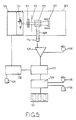
- Fig. 4 is a block diagram of an apparatus according to an aspect of the present invention;
- Figure 5 is a block diagram showing timing and calibration controls used in the embodiments of Figures 6 and 7,
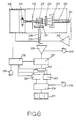
- Figure 6 is a block diagram of an apparatus according to the present invention, and
- Figure 7 is a block diagram of a further apparatus according to the present invention interfaced with a micro-computer for control and result analysis purposes.
- In an example of the present invention, the apparatus comprises a high intensity light source comprising a xenon
flash discharge tube 10, such as is typically used in photography powered by a small dry cell. This tube, in conjunction with interference filters and suitable attenuation means 11, 12, gives a narrow band width source of radiation with a maximum at 479 nm. The filters are desired to give a maximum at 473 nm but production defects may cause a small shift of a few nm from this from filter to filter. - Alternatively, a high intensity output light emitting diode can be used. This has the advantage that the wavelength of the emitted light (e.g.480 nm) can be controlled quite accurately and so reduces the need for extensive filtering.
- A
cuvette 13 is charged with 3.0 ml of physiological saline/4 percent polyethylene glycol, 20µl of Zaponin®/KCN, which is a trademark, and is available from Ortho Pharmaceutical and 5µl of whole blood. 40 µl of anti IgG antiserum is added to this mixture. It is possible to increase the sensitivity of the method according to the present invention by using particle bound antibodies e.g latex bound antibodies which cause agglomerates to form which scatter radiation more effectively. - The
cuvette 13 is made from a suitable transparent material and is placed in the path of thelight 16 from theflash tube 10. Because it is not necessary to effect any pre-treatment to the blood sample before it is introduced into the cuvette, it is possible to reduce the amount of handling of the sample to a minimum. This reduces any contact the operator may have with the blood sample to a minimum and so increases the safety of the present method and apparatus. - A
photo diode detector 14 is arranged to receive anylight 17 which is scattered through a given angle from the sample, in the present case the angle is 90°. Theinterference filters 11 are placed between theflash tube 10 and thedetector 14 such that only light of a specified wavelength is transmitted to thedetector 14. - A
further detector 15 is positioned to detectlight 18 transmitted by the sample at a given wavelength (selected by means of futher filters 20) corresponding to haemoglobin absorption. Thisdetector 15 is linked via control circuitry 19 to theflash tube 10 and terminates the flash when sufficient light has been received. This automatically compensates for the red blood cell content of the sample. - For instance, when it is desired to find the concentration of a particular protein in a sample of whole blood, compensation is needed.
- Referring now to Figs 1-3, the wavelength of light used is chosen such that the signal from the complex is relatively high and the signal from haemoglobin is at a relative minimum (x) and the total signal relative to background signal is as strong as possible. This is done to ensure that the strength of the signal obtained is mainly effected by the concentration of the complex rather than other incidental factors. In the present case the wavelength chosen is 473 nm (± a few nm due to variations between filters). The
detector 14 is linked to a calibrateddisplay 21 such that the signal may be directly displayed in terms of antigen concentration. - Referring now to Fig. 5 those parts which are the same as shown in Fig. 4 are given the same reference numerals in the 100 series. Located within an
optical chamber 125 are flash charge and trigger circuitry located within a screenedcompartment 126 controlling activation of thexenon discharge tube 110, saidtube 110, interference filter andillumination aperture sample 113, alight sink 127 and thedetector 114 in ascatter aperture pipe 128. Thelight sink 127 serves to absorb any light which is transmitted by the sample and so prevent any reflections within thechamber 125 which may affect the readings. Thedetector 114 andaperture pipe 128 are arranged in such a way that only light which has been scattered through substantially 90° falls upon thedetector 114. Thedetector 114 emits a signal to adetector amplifier 129 which has means 130 for adjusting the gain on theamplifier 129 and hence allows adjustment of the sensitivity of the apparatus. - A signal from the
amplifier 129 is taken to apeak detector 131 which is connected to atiming circuit 132 provided with adjustment means 133. The timing circuit is also connected to the trigger circuitry incompartment 126. Thetiming circuit 132 controls the activation of thetube 110 and thepeak detector 131. Activation of thetiming circuits 132 causes the tube to discharge at a given time after the immunochemical reaction has been initiated in thecuvette 113. Thepeak detector 131 is activated a short time after thetube 110 is discharged in order to eliminate any e.m.f. peak effects caused by the discharge. Thepeak detector 131 continues to function until a peak is reached when no more readings are taken. The signal from thepeak detector 131 is fed into adigital multimeter 134 which is provided with controls for zeroing 135 andcalibration 136. The readings from the multimeter are shown on adigital display 121. - This apparatus does not cater for compensation for differences between test blanks or in differences in haemoglobin level between samples, and is not therefore exemplary of the invention, but merely shows timing and calibration controls included in the embodiments of Figures 6 and 7.
- Activation of the timing
circuits 132 may be achieved manually by operating a switch when thecuvette 113 has been inserted, or insertion of thecuvette 113 can cause automatic operation by use of a micro-switch. - Referring now to Fig. 6 those parts which correspond to those shown in previous drawings are given the same reference numerals in the 200 series. In this embodiment, the
interference filter 211 is located between thecuvette 213 and thedetector 214. Afurther interference filter 220 is located between thecuvette 213 and thelight sink 227. Atransmission aperture pipe 240 having afurther detector 241 therein is provided in thelight sink 227 and is arranged to receive light which has been transmitted through the sample. The signal from thefurther detector 241 is passed to an associatedamplifier 242 which in turn sends a signal to the flash change and trigger circuitry. This arrangement is used to control the duration of the flash in order to compensate for the amount of light absorbed by the haemoglobin in the sample. - The signal from the
detector 214 is fed to apeak detector 231 via anamplifier 229 as before, the peak detector being controlled by timingcircuitry 232. However, the output from the peak detector is fed through a two-way switch 243 to either a first sample and holdcircuit 244 or a second sample and holdcircuit 245. Both sample and holdcircuits switch 243 are controlled by the timingcircuits 232. The output of the sample and holdcircuits digital multimeter 234 withcalibration control 236 and displayed on adigital display 221. - In use, a first reading is taken when the immunological reaction is initiated and the
switch 243 is operated by thecircuit 232 such that the output from thepeak detector 231 is fed to the first sample and holdcircuits 244. At a pre-set time after this first reading, a second reading is taken and is fed to the second sample and holdcircuits 245. The output from the first sample and hold circuits is fed to a zero reference pin on themultimeter 234 and so the output from the second sample and holdcircuits 245 can be displayed to give the change in scatter intensity after said pre-set time interval, the zero reading being used to compensate for any scatter from the sample which is not due to the immunological reaction. - In Fig. 7 parts corresponding to these parts shown in previous drawings are given the same reference numerals in the 300 series. The apparatus shown in Fig. 7 is controlled by a micro computer which handles timing control and data analysis operations.
- In addition to the
detectors tube 310. This can be used to improve the accuracy of the apparatus. The output from eachdetector amplifier respective peak detector peak detector 331a, 33ab, 331c is fed to amultiplexer 354 and then to an analogue todigital converter 355 which is connected to amicro computer 356. Themicro computer 356 replaces the timing circuits shown in previous embodiments and also controlssample processor 357 which can process the sample accurately before the readings are taken and so improve overall accuracy. - When there is high interference to the signal from the complex due to other proteins, it is preferable to use a rate determining method. In this case, measurements are taken at specific time intervals after the blood sample and the antigen are mixed. Typically, a number of readings over a few seconds and the detected signals are fed to data analysis means which allows determination of the rate of formation of the antigen/antibody complex and hence the concentration of the antibody.
- Although the present invention has been described with relation to determination of antigen content, it will be clear that this method may also be employed to determine the content of a first antigen protein in a sample of blood by utilizing one or more other antibodies which is specific to the first antibody.
Claims (11)
- A method of quantifying, in a whole blood sample, a molecular component which will react with a reagent to form an antigen-antibody complex, comprising the steps of mixing said sample with said reagent to form said complex, exposing said sample to a source of light radiation and measuring the intensity of radiation scattered through a given angle by said complex, characterised in that the red cells in said sample are lysed, in that the wavelength of the radiation is such that the ratio of the intensity of detected scattered radiation to that of radiation absorbed by haemoglobin from said lysed red cells is maximised, and in that the intensity of light transmitted through said sample is detected and used to modify the levels of detected scattered light so that measurements derived therefrom substantially correspond to the levels of said antigen-antibody complex.
- A method as claimed in Claim 1 which includes modification of said levels of detected scattered light in response to the incident light from said source onto said sample.
- A method as claimed in Claim 1 or Claim 2 in which the wavelength of said radiation is selected from the range 460-530 nm.
- A method as claimed in Claim 2 in which the wavelength of said radiation is selected from the range 460-510 nm.
- A method as claimed in any preceding claim in which the intensity of said scattered radiation is measured at time intervals, to determine the rate of formation of said antigen-antibody complex.
- A method as claimed in any preceding claim in which said radiation is obtained from a xenon flash tube.
- A method as claimed in any preceding claim in which said component is a protein.
- A method as claimed in Claim 7 in which said protein is an immunoglobulin.
- An apparatus for carrying out the method of any one of Claims 1 to 8, comprising means (13) for receiving said sample and said reagent, a light source (10) for illuminating said sample, and devices (14, 114 or 214 or 314) for detecting the intensity of light scattered at a predetermined angle by said sample, and for quantifying said component from said detected intensity, characterised in that said light has a wavelength such that the ratio of the intensity of detected scattered radiation to that of radiation absorbed by the haemoglobin from said lysed red cells is maximised, and in that said apparatus includes a device (15 or 241 or 341) for detecting the intensity of light transmitted through said sample and a circuit (19 or 242 or 342, 354, 355, 356) for modifying the levels of detected scattered light so that measurements derived therefrom substantially correspond to the levels of said antigen-antibody complex.
- An apparatus as claimed in Claim 9 which includes a device (15, 19) for generating a signal corresponding to the amount of light transmitted by the sample, said light source (10) being responsive to a predetermined level of said signal to terminate said radiation.
- An apparatus as claimed in Claim 9 or Claim 10 in which said light source (10) is a xenon flash tube.
Priority Applications (1)
| Application Number | Priority Date | Filing Date | Title |
|---|---|---|---|
| AT86308159T ATE75048T1 (en) | 1985-10-25 | 1986-10-21 | METHOD AND APPARATUS FOR DETERMINING ANTIBODY CONTENT OF BLOOD. |
Applications Claiming Priority (2)
| Application Number | Priority Date | Filing Date | Title |
|---|---|---|---|
| GB858526355A GB8526355D0 (en) | 1985-10-25 | 1985-10-25 | Determination of antibody content of blood |
| GB8526355 | 1985-10-25 |
Publications (2)
| Publication Number | Publication Date |
|---|---|
| EP0223427A1 EP0223427A1 (en) | 1987-05-27 |
| EP0223427B1 true EP0223427B1 (en) | 1992-04-15 |
Family
ID=10587247
Family Applications (1)
| Application Number | Title | Priority Date | Filing Date |
|---|---|---|---|
| EP86308159A Expired - Lifetime EP0223427B1 (en) | 1985-10-25 | 1986-10-21 | Method and apparatus for the determination of the antibody content of blood |
Country Status (10)
| Country | Link |
|---|---|
| US (1) | US4889815A (en) |
| EP (1) | EP0223427B1 (en) |
| JP (1) | JPS62142274A (en) |
| AT (1) | ATE75048T1 (en) |
| AU (1) | AU604218B2 (en) |
| CA (1) | CA1286222C (en) |
| DE (1) | DE3684880D1 (en) |
| DK (1) | DK509686A (en) |
| FI (1) | FI864286A7 (en) |
| GB (1) | GB8526355D0 (en) |
Families Citing this family (16)
| Publication number | Priority date | Publication date | Assignee | Title |
|---|---|---|---|---|
| US5017009A (en) * | 1986-06-26 | 1991-05-21 | Ortho Diagnostic Systems, Inc. | Scattered total internal reflectance immunoassay system |
| US4935346A (en) | 1986-08-13 | 1990-06-19 | Lifescan, Inc. | Minimum procedure system for the determination of analytes |
| US5736407A (en) * | 1994-01-05 | 1998-04-07 | Degussa Aktiengesellschaft | Process for determining the thickening effect of silicon dioxide |
| US6855562B1 (en) | 1996-07-30 | 2005-02-15 | Horiba, Ltd. | Immunoassay method for lyzed whole blood |
| JP3249919B2 (en) * | 1996-07-30 | 2002-01-28 | 株式会社堀場製作所 | Immunoassay method |
| EP0905514B1 (en) * | 1997-09-27 | 2003-11-26 | Horiba, Ltd. | Blood cell count/immunoassay apparatus using whole blood |
| DE19948587A1 (en) * | 1999-10-08 | 2001-04-12 | Dade Behring Marburg Gmbh | Spectrophotometric and nephelometric detection unit |
| US6458326B1 (en) | 1999-11-24 | 2002-10-01 | Home Diagnostics, Inc. | Protective test strip platform |
| US6900059B1 (en) * | 1999-11-26 | 2005-05-31 | Associates Of Cape Cod, Inc. | Reader for conducting assays |
| US6562625B2 (en) | 2001-02-28 | 2003-05-13 | Home Diagnostics, Inc. | Distinguishing test types through spectral analysis |
| US6541266B2 (en) | 2001-02-28 | 2003-04-01 | Home Diagnostics, Inc. | Method for determining concentration of an analyte in a test strip |
| US6525330B2 (en) | 2001-02-28 | 2003-02-25 | Home Diagnostics, Inc. | Method of strip insertion detection |
| US7016791B2 (en) * | 2002-10-02 | 2006-03-21 | Airadvice, Inc. | Particle sizing refinement system |
| AU2003279801A1 (en) * | 2002-10-02 | 2004-04-23 | Airadvice, Inc. | Method and apparatus for particle sizing |
| US11733170B2 (en) * | 2019-08-07 | 2023-08-22 | International Business Machines Corporation | Optical sensor system for quantitative colorimetric liquid analysis |
| CN111157469A (en) * | 2019-12-31 | 2020-05-15 | 河海大学常州校区 | Gas-liquid two-phase discharge liquid-phase active ingredient online detection device and method |
Family Cites Families (11)
| Publication number | Priority date | Publication date | Assignee | Title |
|---|---|---|---|---|
| US4080264A (en) * | 1976-03-01 | 1978-03-21 | Massachusetts Institute Of Technology | Immunoassay by light scattering spectroscopy |
| US4204837A (en) * | 1978-03-14 | 1980-05-27 | Beckman Instruments, Inc. | Method of rate immunonephelometric analysis |
| JPS5925460B2 (en) * | 1978-05-19 | 1984-06-18 | 株式会社日立製作所 | Nephelometric immunoassay method and device |
| DE2918342A1 (en) * | 1979-05-07 | 1980-11-20 | Behringwerke Ag | LATEX REAGENT |
| US4284412A (en) * | 1979-07-13 | 1981-08-18 | Ortho Diagnostics, Inc. | Method and apparatus for automated identification and enumeration of specified blood cell subclasses |
| US4419583A (en) * | 1980-05-31 | 1983-12-06 | Noeller Hans Guenter | Polarization fluoroimmunoassay with pulsed light source |
| DE3026077A1 (en) * | 1980-07-10 | 1982-06-09 | Hans Günter Priv.Doz. Dr.med. 6900 Heidelberg Nöller | High-intensity flashlight nephelometer - using xenon flash bulb in one or a few pulses |
| US4766083A (en) * | 1982-04-04 | 1988-08-23 | Wako Pure Chemical Industries, Ltd. | Method for the photometric determination of biological agglutination |
| JPS58173455A (en) * | 1982-04-05 | 1983-10-12 | Wako Pure Chem Ind Ltd | Measurement of light scattering |
| FR2531718B1 (en) * | 1982-08-16 | 1986-11-21 | Sanofi Sa | REAGENT ALLOWING A VERY HIGH SENSITIVITY OF THE CHARACTERISTIC ANTIGEN OF HEPATITIS B VIRUS IN HUMAN BIOLOGICAL LIQUIDS |
| US5398297A (en) * | 1992-07-27 | 1995-03-14 | Tektronix, Inc. | Improved color rendering method for intensity-variable printing based upon a dithering table |
-
1985
- 1985-10-25 GB GB858526355A patent/GB8526355D0/en active Pending
-
1986
- 1986-10-21 DE DE8686308159T patent/DE3684880D1/en not_active Expired - Fee Related
- 1986-10-21 AT AT86308159T patent/ATE75048T1/en not_active IP Right Cessation
- 1986-10-21 EP EP86308159A patent/EP0223427B1/en not_active Expired - Lifetime
- 1986-10-22 AU AU64358/86A patent/AU604218B2/en not_active Ceased
- 1986-10-23 FI FI864286A patent/FI864286A7/en not_active Application Discontinuation
- 1986-10-23 US US07/922,359 patent/US4889815A/en not_active Expired - Fee Related
- 1986-10-24 DK DK509686A patent/DK509686A/en not_active Application Discontinuation
- 1986-10-24 JP JP61252088A patent/JPS62142274A/en active Pending
- 1986-10-24 CA CA000521348A patent/CA1286222C/en not_active Expired - Fee Related
Also Published As
| Publication number | Publication date |
|---|---|
| US4889815A (en) | 1989-12-26 |
| FI864286A7 (en) | 1987-04-26 |
| EP0223427A1 (en) | 1987-05-27 |
| FI864286A0 (en) | 1986-10-23 |
| GB8526355D0 (en) | 1985-11-27 |
| AU6435886A (en) | 1987-04-30 |
| CA1286222C (en) | 1991-07-16 |
| DK509686D0 (en) | 1986-10-24 |
| ATE75048T1 (en) | 1992-05-15 |
| DE3684880D1 (en) | 1992-05-21 |
| DK509686A (en) | 1987-04-26 |
| AU604218B2 (en) | 1990-12-13 |
| JPS62142274A (en) | 1987-06-25 |
Similar Documents
| Publication | Publication Date | Title |
|---|---|---|
| US4889815A (en) | Nephelometric method for determination of an antigen or antibody content in whole blood | |
| US4925299A (en) | Hemoglobin detector | |
| US5478750A (en) | Methods for photometric analysis | |
| US5750410A (en) | Method of and apparatus for immune analysis | |
| JPH0619351B2 (en) | Latex agglutination reaction measuring device | |
| US4988630A (en) | Multiple beam laser instrument for measuring agglutination reactions | |
| ATE239911T1 (en) | ANALYZER | |
| NO750639L (en) | ||
| CA1047788A (en) | Nephelometer having means semiautomatically cancelling components from scattering by particles smaller or larger than those of interest | |
| JPH03503454A (en) | Optical reader for immunoassays | |
| EP0903571A2 (en) | Apparatus and method for determining the concentration of specific substances | |
| JPS61202142A (en) | Analyzing method and apparatus using absorbance | |
| EP0786665B1 (en) | Method and apparatus for immune analysis | |
| JP2002506981A (en) | Method and apparatus for measuring protein | |
| US6887430B1 (en) | Apparatus for immune analysis | |
| JPH07113635B2 (en) | Method for determining prozone in immune reaction | |
| US4240753A (en) | Method for the quantitative determination of turbidities, especially of immune reactions | |
| JP4536968B2 (en) | Blood test equipment | |
| JPH03221837A (en) | Method and device for measuring body to be tested | |
| EP0433629B1 (en) | A method for the qualitative and quantitative determination of antibodies against bacterial antigens by means of the photometric measurement of agglutination | |
| JPH01313737A (en) | Inspection device for body to be inspected | |
| JPS6058826B2 (en) | Nephelometry method | |
| JPH0619350B2 (en) | Body fluid component analysis method and apparatus | |
| JP6657016B2 (en) | Automatic analyzer | |
| WO2025220348A1 (en) | Method for testing for blood in milk, and device for testing for blood in milk |
Legal Events
| Date | Code | Title | Description |
|---|---|---|---|
| PUAI | Public reference made under article 153(3) epc to a published international application that has entered the european phase |
Free format text: ORIGINAL CODE: 0009012 |
|
| AK | Designated contracting states |
Kind code of ref document: A1 Designated state(s): AT BE CH DE ES FR GB GR IT LI LU NL SE |
|
| 17P | Request for examination filed |
Effective date: 19871118 |
|
| 17Q | First examination report despatched |
Effective date: 19891009 |
|
| GRAA | (expected) grant |
Free format text: ORIGINAL CODE: 0009210 |
|
| AK | Designated contracting states |
Kind code of ref document: B1 Designated state(s): AT BE CH DE ES FR GB GR IT LI LU NL SE |
|
| PG25 | Lapsed in a contracting state [announced via postgrant information from national office to epo] |
Ref country code: IT Free format text: LAPSE BECAUSE OF FAILURE TO SUBMIT A TRANSLATION OF THE DESCRIPTION OR TO PAY THE FEE WITHIN THE PRE;WARNING: LAPSES OF ITALIAN PATENTS WITH EFFECTIVE DATE BEFORE 2007 MAY HAVE OCCURRED AT ANY TIME BEFORE 2007. THE CORRECT EFFECTIVE DATE MAY BE DIFFERENT FROM THE ONE RECORDED.SCRIBED TIME-LIMIT Effective date: 19920415 Ref country code: NL Effective date: 19920415 Ref country code: SE Effective date: 19920415 Ref country code: LI Effective date: 19920415 Ref country code: AT Effective date: 19920415 Ref country code: GR Free format text: LAPSE BECAUSE OF FAILURE TO SUBMIT A TRANSLATION OF THE DESCRIPTION OR TO PAY THE FEE WITHIN THE PRESCRIBED TIME-LIMIT Effective date: 19920415 Ref country code: CH Effective date: 19920415 Ref country code: FR Effective date: 19920415 Ref country code: BE Effective date: 19920415 |
|
| REF | Corresponds to: |
Ref document number: 75048 Country of ref document: AT Date of ref document: 19920515 Kind code of ref document: T |
|
| REF | Corresponds to: |
Ref document number: 3684880 Country of ref document: DE Date of ref document: 19920521 |
|
| PG25 | Lapsed in a contracting state [announced via postgrant information from national office to epo] |
Ref country code: ES Free format text: LAPSE BECAUSE OF FAILURE TO SUBMIT A TRANSLATION OF THE DESCRIPTION OR TO PAY THE FEE WITHIN THE PRESCRIBED TIME-LIMIT Effective date: 19920726 |
|
| REG | Reference to a national code |
Ref country code: CH Ref legal event code: PL |
|
| EN | Fr: translation not filed | ||
| NLV1 | Nl: lapsed or annulled due to failure to fulfill the requirements of art. 29p and 29m of the patents act | ||
| PG25 | Lapsed in a contracting state [announced via postgrant information from national office to epo] |
Ref country code: LU Free format text: LAPSE BECAUSE OF NON-PAYMENT OF DUE FEES Effective date: 19921031 |
|
| PLBE | No opposition filed within time limit |
Free format text: ORIGINAL CODE: 0009261 |
|
| STAA | Information on the status of an ep patent application or granted ep patent |
Free format text: STATUS: NO OPPOSITION FILED WITHIN TIME LIMIT |
|
| 26N | No opposition filed | ||
| PGFP | Annual fee paid to national office [announced via postgrant information from national office to epo] |
Ref country code: GB Payment date: 19951012 Year of fee payment: 10 |
|
| PGFP | Annual fee paid to national office [announced via postgrant information from national office to epo] |
Ref country code: DE Payment date: 19951026 Year of fee payment: 10 |
|
| PG25 | Lapsed in a contracting state [announced via postgrant information from national office to epo] |
Ref country code: GB Effective date: 19961021 |
|
| GBPC | Gb: european patent ceased through non-payment of renewal fee |
Effective date: 19961021 |
|
| PG25 | Lapsed in a contracting state [announced via postgrant information from national office to epo] |
Ref country code: DE Effective date: 19970701 |