EP0223017A1 - Process for metering fluid metal, and pump therefor - Google Patents
Process for metering fluid metal, and pump therefor Download PDFInfo
- Publication number
- EP0223017A1 EP0223017A1 EP86113282A EP86113282A EP0223017A1 EP 0223017 A1 EP0223017 A1 EP 0223017A1 EP 86113282 A EP86113282 A EP 86113282A EP 86113282 A EP86113282 A EP 86113282A EP 0223017 A1 EP0223017 A1 EP 0223017A1
- Authority
- EP
- European Patent Office
- Prior art keywords
- delivery
- feed
- liquid metal
- pump
- funding
- Prior art date
- Legal status (The legal status is an assumption and is not a legal conclusion. Google has not performed a legal analysis and makes no representation as to the accuracy of the status listed.)
- Granted
Links
Images
Classifications
-
- B—PERFORMING OPERATIONS; TRANSPORTING
- B22—CASTING; POWDER METALLURGY
- B22D—CASTING OF METALS; CASTING OF OTHER SUBSTANCES BY THE SAME PROCESSES OR DEVICES
- B22D39/00—Equipment for supplying molten metal in rations
Definitions
- the present invention relates to a method for metering liquid metal according to the preamble of claim 1, in particular using an electromagnetic pump.
- EP-A-0 095 620 a method for regulating the delivery rate of an inductive liquid metal feed pump is already known, in which several different parameters are used to regulate the pump. From this document it is also known that the liquid metal level must always be held at a defined position in the conveyor pipe during the breaks in delivery in order to enable precise metering.
- the object of the present invention is to create a simplified method for metering liquid metal, which requires little instrumentation and control technology.
- a method according to the main claim is proposed.
- the invention is based on the knowledge that the delivery rate, which is necessary in the delivery breaks to maintain a certain delivery head in a feed system, is already required for the control Contains information about the conveyor system. With a low level of the melt in the melt container, for example, or with a high melt temperature, an increased delivery rate is required even during the delivery breaks to maintain the specified delivery head in the feed system. It is therefore not necessary to measure the corresponding parameters in the melt container.
- the delivery rate of the feed pump is regulated and the fill level, ie the height of the liquid metal column in the feed system, is measured.
- the fill level ie the height of the liquid metal column in the feed system.
- the liquid metal flow in the feed system is throttled by means of a defined throttle point.
- a defined throttle point In the case of a pure time control of the metering device, it is important that constant delivery quantities per unit of time are always achieved in the delivery times, whereby these should not change in the course of the operating time. The influence of other deposits in the feed system is greatly reduced by a defined throttle point, since the cross-section of the throttle point essentially determines the delivery rate per unit of time.
- the area of the feed system which is not filled with liquid metal is kept under protective gas in the feed breaks, namely by gushing feed at the end of the feed times and by low feed in the feed breaks.
- This measure which is particularly important for easily oxidizable liquid metals, for example magnesium, additionally reduces the risk of oxidic deposits in the feed system.
- Claim 6 describes an electromagnetic pump that is particularly suitable for the method. Normally, each such pump shows a functional dependency of the delivery pressure ⁇ P for a given square of the coil current I2 on the temperature of the melt. According to the invention, the pump is designed so that ⁇ P / I2 is as independent as possible of the melt temperature. This is possible through appropriate geometry and coil dimensioning. As a result, the control only needs to take into account the liquid metal level in the melt container, but not the melt temperature, which increases the accuracy.
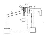
- the drawing shows a schematic representation of a metering system for liquid metal with its associated control devices.
- the casting head 1 which can be filled with liquid metal by a liquid metal feed pump 2 via a feed pipe 3, is particularly emphasized in scale.
- the liquid metal comes from a conventional melt container or the like, not shown here.
- the casting head 1 has a prechamber 4, an overflow section 7 and an outlet chamber 8.
- a fill level measuring arrangement 5 is arranged in the pre-chamber 4, preferably an inductive fill level meter which can be inserted from below into a corresponding pocket tube. By means of this fill level meter 5, the liquid metal level 6 in the antechamber 4 can be measured precisely and precisely adjusted to a specific target value in the delivery pauses.
- the overflow section 7 or, as shown here, the outlet chamber 8 has a throttle point 9 which forms a defined delivery cross section for the liquid metal. Furthermore, the outlet chamber 8, preferably behind the throttle point 9, has a protective gas feed 10 through which protective gas can be supplied.
- a slide valve 11 at the lower end 12 of the outlet chamber 8 enables the outlet chamber to be closed during breaks in delivery.
- a controllable valve 13 enables protective gas to be supplied in gushes from a storage container 14.
- Central control electronics 16 control the entire metering process. For this purpose, the electronics are first supplied with the level values measured in a level measuring electronics 15 in the prechamber 4. From this, the control electronics 16 determines the delivery rate of the delivery pump 2 during the delivery breaks, so that a precise fill level 6 can be maintained.
- the control circuit 16 increases the delivery rate for a certain time by a certain amount, so that the desired amount of liquid metal is promoted.
- the delivery rate is then reduced again to the initial value and the liquid metal level 6 of the prechamber is brought to the previous setpoint.
- the valve 13 is opened at the end of the conveying process and a surge of protective gas is let into the outlet chamber 8. This prevents the entry of oxygen into the casting head 1.
- By closing the slide valve 11, the oxygen-free atmosphere in the casting head 1 is maintained and dripping is prevented.
- the proposed pouring head is particularly suitable for conveying liquid metal in connection with electromagnetic feed pumps, since these have good controllability and fast response times.
Landscapes
- Engineering & Computer Science (AREA)
- Mechanical Engineering (AREA)
- Casting Support Devices, Ladles, And Melt Control Thereby (AREA)
- Feeding, Discharge, Calcimining, Fusing, And Gas-Generation Devices (AREA)
- Loading And Unloading Of Fuel Tanks Or Ships (AREA)
- Infusion, Injection, And Reservoir Apparatuses (AREA)
Abstract
Description
Die vorliegende Erfindung betrifft ein Verfahren zur Dosierung von Flüssigmetall nach dem Oberbegriff des Anspruchs 1, insbesondere unter Verwendung einer elektromagnetischen Pumpe. Aus der EP-A-0 095 620 ist bereits ein Verfahren zur Regelung der Förderleistung einer induktiven Flüssigmetallförderpumpe bekannt, bei welcher mehrere verschiedene Parameter zur Regelung der Pumpe benutzt werden. Aus dieser Schrift ist auch bekannt, daß während der Förderpausen der Flüssigmetallspiegel immer an einer definierten Stelle im Förderrohr gehalten werden muß, um eine präzise Dosierung zu ermöglichen.The present invention relates to a method for metering liquid metal according to the preamble of claim 1, in particular using an electromagnetic pump. From EP-A-0 095 620 a method for regulating the delivery rate of an inductive liquid metal feed pump is already known, in which several different parameters are used to regulate the pump. From this document it is also known that the liquid metal level must always be held at a defined position in the conveyor pipe during the breaks in delivery in order to enable precise metering.
Die bisherigen Verfahren zur Dosierung von Flüssigmetall gingen in ihrem Regelungs- bzw. Steuerkonzept davon aus, daß für eine präzise Dosierung mehrere Parameter, so beispielsweise die Höhe der Schmelze im Vorratsbehälter und deren Temperatur, bekannt sein mußten, damit die Förderleistung der Pumpe in den Förderzeiten entsprechend eingestellt werden konnte.The previous methods for dosing liquid metal assumed in their regulation or control concept that for precise dosing several parameters, such as the height of the melt in the storage container and its temperature, had to be known in order for the delivery rate of the pump in the delivery times could be set accordingly.
Aufgabe der vorliegenden Erfindung ist die Schaffung eines vereinfachten Verfahrens zur Dosierung von Flüssigmetall, welches mit einem geringen Aufwand an Instrumentierung und Regelungstechnik auskommt. Zur Lösung dieser Aufgabe wird ein Verfahren nach dem Hauptanspruch vorgeschlagen. Die Erfindung geht dabei von der Erkenntnis aus, daß die Förderleistung, welche in den Förderpausen zur Einhaltung einer bestimmten Förderhöhe in einem Zuführsystem nötig ist, schon alle für die Regelung benötigten Informationen über das Fördersystem enthält. Bei einem niedrigen Spiegel der Schmelze im Schmelzenbehälter beispielsweise oder bei hoher Schmelzentemperatur wird schon in den Förderpausen eine erhöhte Förderleistung zur Einhaltung der bestimmten Förderhöhe im Zuführsystem benötigt. Es ist daher nicht nötig, die entsprechenden Parameter im Schmelzenbehälter zu messen. Vielmehr kann man während der Förderzeiten die Pumpleistung immer um einen bestimmten Betrag über die Pausenleistung erhöhen und erreicht dadurch eine konstante Fördermenge pro Zeiteinheit, so daß eine präzise Dosierung durch reine Zeitsteuerung des Pumpvorganges möglich ist. Dies vereinfacht die Steuerung des Dosiervorganges Außer einem Füllstandsfühler wird keine weitere Instrumentierung benötigt. Das bisher beschriebene Verfahren weist jedoch bei sehr hohen Anforderungen an die Genauigkeit eine Schwierigkeit auf. Die Flüssigmetallsäule im Zuführsystem ist eine schwingfähige Masse, deren Einregelung auf einen bestimmten Sollwert mit einem einfachen Proportionalregler nicht genügend genau ist. Es muß daher ein Regler mit Integralanteil, vorzugsweise ein PID-Regler oder ein ID-Regler verwendet werden. Geregelt wird die Förderleistung der Förderpumpe und gemessen wird der Füllstand, d. h. die Höhe der Flüssigmetallsäulle im Zuführsystem. Bei dieser Art der Regelung stellt sich keine konstante Förderleistung zur Einhaltung einer bestimmten Flüssigmetallsäulenhöhe ein, sondern es finden während der Förderpausen ständig kleine Regelschwankungen statt. Dennoch läßt sich der Mittelwert der Förderleistung in den Förderpausen, welcher für das erfindungsgemäße Verfahren von Bedeutung ist, leicht ermitteln, indem der Integralanteil des Reglers getrennt gemessen bzw. berechnet wird, woraus sich dann der Mittelwert der Förderleistung ergibt, zu dem die zusätzliche Förderleistung in den Förderzeiten addiert werden muß.The object of the present invention is to create a simplified method for metering liquid metal, which requires little instrumentation and control technology. To solve this problem, a method according to the main claim is proposed. The invention is based on the knowledge that the delivery rate, which is necessary in the delivery breaks to maintain a certain delivery head in a feed system, is already required for the control Contains information about the conveyor system. With a low level of the melt in the melt container, for example, or with a high melt temperature, an increased delivery rate is required even during the delivery breaks to maintain the specified delivery head in the feed system. It is therefore not necessary to measure the corresponding parameters in the melt container. Rather, one can always increase the pumping capacity during the delivery times by a certain amount over the break performance and thereby achieve a constant delivery rate per unit of time, so that precise metering is possible through pure time control of the pumping process. This simplifies the control of the dosing process. Apart from a level sensor, no further instrumentation is required. However, the method described so far has a problem with very high demands on the accuracy. The liquid metal column in the feed system is an oscillating mass, the adjustment of which to a certain setpoint is not sufficiently precise with a simple proportional controller. A controller with an integral component, preferably a PID controller or an ID controller, must therefore be used. The delivery rate of the feed pump is regulated and the fill level, ie the height of the liquid metal column in the feed system, is measured. With this type of control, there is no constant delivery rate to maintain a certain liquid metal column height, but there are constantly small control fluctuations during the delivery breaks. Nevertheless, the mean value of the delivery rate during the delivery breaks, which is important for the method according to the invention, can easily be determined by separately measuring or calculating the integral part of the controller, which then gives the average value of the delivery rate at which the additional delivery rate in the funding times must be added.
In weiterer Ausgestaltung der Erfindung wird im Anspruch 3 vorgeschlagen, daß der Flüssigmetallstrom im Zuführsystem, vorzugsweise in dessen End- bzw. Auslaßbereich mittels einer definierten Drosselstelle gedrosselt wird. Bei einer reinen Zeitsteuerung der Dosiervorrichtung ist es wichtig, daß in den Förderzeiten immer konstante Fördermengen pro Zeiteinheit erreicht werden, wobei sich diese im Laufe der Betriebszeit nicht verändern sollen. Durch eine definierte Drosselstelle werden Einflüsse von sonstigen Ablagerungen im Zuführsystem stark verringert, da im wesentlichen der Querschnitt der Drosselstelle die Fördermenge pro Zeiteinheit bestimmt.In a further embodiment of the invention it is proposed in claim 3 that the liquid metal flow in the feed system, preferably in its end or outlet area, is throttled by means of a defined throttle point. In the case of a pure time control of the metering device, it is important that constant delivery quantities per unit of time are always achieved in the delivery times, whereby these should not change in the course of the operating time. The influence of other deposits in the feed system is greatly reduced by a defined throttle point, since the cross-section of the throttle point essentially determines the delivery rate per unit of time.
In weiterer Ausgestaltung der Erfindung wird im Anspruch 4 vorgeschlagen, daß in den Förderpausen der nicht mit Flüssigmetall gefüllte Bereich des Zuführsystems unter Schutzgas gehalten wird, und zwar durch schwallartige Zufuhr am Ende der Förderzeiten und durch geringe Zufuhr in den Förderpausen. Diese Maßnahme, welche insbesondere für leicht oxidierbare Flüssigmetalle, beispielsweise Magnesium, von Bedeutung ist, verringert zusätzlich das Risiko von oxidischen Ablagerungen im Zuführsystem.In a further embodiment of the invention it is proposed in claim 4 that the area of the feed system which is not filled with liquid metal is kept under protective gas in the feed breaks, namely by gushing feed at the end of the feed times and by low feed in the feed breaks. This measure, which is particularly important for easily oxidizable liquid metals, for example magnesium, additionally reduces the risk of oxidic deposits in the feed system.
Ergänzend dazu wird im Anspruch 5 noch vorgeschlagen, daß am Ende der Förderzeiten nach Beendigung des Flüssigmetallflusses das Ende des Zuführsystems mittels eines Schiebers oder dergleichen verschlossen wird. Dadurch wird das System weitgehend gegen Sauerstoffzufuhr abgedichtet, ohne daß der Verbrauch an Schutzgas besonders hoch wird.In addition, it is also proposed in
In Anspruch 6 wird eine besonders für das Verfahren geeignete elektromagnetische Pumpe beschrieben. Normalerweise zeigt jede solche Pumpe eine funktionale Abhängigkeit des Förderdruckes ΔP bei gegebenem Quadrat des Spulenstromes I² von der Temperatur der Schmelze. Erfindungsgemäß wird die Pumpe so ausgelegt, daß ΔP /I2 möglichst unabhängig von der Schmelzentemperatur ist. Dies ist durch entsprechende Geometrie und Spulendimensionierung möglich. Dadurch braucht die Regelung nur noch den Flüssigmetallspiegel im Schmelzenbehälter, nicht jedoch die Schmelzentemperatur zu berücksichtigen, wodurch die Genauigkeit erhöht wird.Claim 6 describes an electromagnetic pump that is particularly suitable for the method. Normally, each such pump shows a functional dependency of the delivery pressure ΔP for a given square of the coil current I² on the temperature of the melt. According to the invention, the pump is designed so that ΔP / I2 is as independent as possible of the melt temperature. This is possible through appropriate geometry and coil dimensioning. As a result, the control only needs to take into account the liquid metal level in the melt container, but not the melt temperature, which increases the accuracy.
Die Zeichnung zeigt in schematischer Darstellung ein Dosiersystem für Flüssigmetall mit seinen zugehörigen Regeleinrichtungen. Besonders im Maßstab herausgestellt ist der Gießkopf 1, welcher von einer Flüssigmetallförderpumpe 2 über ein Zuführrohr 3 mit Flüssigmetall gefüllt werden kann. Das Flüssigmetall stammt aus einem hier nicht dargestellten üblichen Schmelzenbehälter oder dergleichen. Der Gießkopf 1 weist eine Vorkammer 4, einen Überlaufabschnitt 7 und eine Auslaßkammer 8 auf. In der Vorkammer 4 ist eine Füllstandsmeßanordnung 5 angeordnet, und zwar vorzugsweise ein induktiver Füllstandsmesser, welcher von unten in ein entsprechendes Sackrohr einführbar ist. Mittels dieses Füllstandsmessers 5 kann der Flüssigmetallspiegel 6 in der Vorkammer 4 genau gemessen und in den Förderpausen auf einen ganz bestimmten Sollwert präzise eingeregelt werden. Der Überlaufabschnitt 7 bzw., wie hier dargestellt die Auslaßkammer 8 weist eine Drosselstelle 9 auf, welche einen definierten Förderquerschnitt für das Flüssigmetall bildet. Ferner weist die Auslaßkammer 8, vorzugsweise hinter der Drosselstelle 9 eine Schutzgaseinspeisung 10 auf, durch welche Schutzgas zugeführt werden kann. Ein Verschlußschieber 11 am unteren Ende 12 der Auslaßkammer 8, ermöglicht ein Verschließen der Auslaßkammer in Förderpausen. Ein steuerbares Ventil 13 ermöglicht die schwallweise Zufuhr von Schutzgas aus einem Vorratsbehälter 14. Eine zentrale Steuerelektronik 16 steuert den gesamten Dosiervorgang. Dazu wird die Elektronik zunächst mit den in einer Füllstandsmeßeektronik 15 gemessenen Füllstandswerten in der Vorkammer 4 beaufschlagt. Daraus bestimmt die Steuerelektronik 16 die Förderleistung der Förderpumpe 2 in den Förderpausen, so daß ein präziser Füllstand 6 eingehalten werden kann. Während der Förderzeiten erhöht die Steuerschaltung 16 die Förderleistung für eine bestimmte Zeit um einen bestimmten Betrag, so daß die gewünschte Flüssigmetallmenge gefördert wird. Anschließend wird die Förderleistung wieder auf den Ausgangswert reduziert und der Flüssigmetallspiegel 6 der Vorkammer auf den vorherigen Sollwert gebracht. Gleichzeitig wird bei Beendigung des Fördervorganges das Ventil 13 geöffnet und ein Schwall Schutzgas in die Auslaßkammer 8 eingelassen. Dadurch wird der Zutritt von Sauerstoff in den Gießkopf 1 verhindert. Durch Schließen des Verschlußschiebers 11 wird die sauerstofffreie Atmosphäre im Gießkopf 1 erhalten und ein Nachtropfen verhindert. Der vorgeschlagene Gießkopf eignet sich in besonderer Weise zur Förderung von Flüssigmetall in Verbindung mit elektromagnetischen Förderpumpen, da diese eine gute Regelbarkeit und schnelle Ansprechzeiten besitzen.The drawing shows a schematic representation of a metering system for liquid metal with its associated control devices. The casting head 1, which can be filled with liquid metal by a liquid
Claims (6)
dadurch gekennzeichnet,
daß die Förderleistung während der Förderzeiten immer um einen bestimmten Betrag über die zur Einhaltung der Förderhöhe (6) in den Förderpausen nötige Förderleistung erhöht wird.1. A method for dosing liquid metal, wherein by regulating the delivery rate of a delivery pump (2), in particular an electromagnetic pump, a certain delivery head (6) in a feed system (3, 4, 7, 8) in the delivery pauses by means of a level sensor (5) ) complied with and the funding is increased during the funding periods,
characterized by
that the delivery rate is always increased during the delivery times by a certain amount above the delivery rate required to maintain the funding level (6) in the delivery breaks.
dadurch gekennzeichnet,
daß die Regelung der Förderhöhe während der Förderpausen durch einen Regler mit Integralanteil, vorzugsweise einen PID-Regler oder einen ID-Regler erfolgt, wobei der Integralanteil des Reglers getrennt gemessen bzw. berechnet wird,woraus dann der Mittelwert der Förderleistung in den Förderpausen bestimmt wird, zu dem die zusätzliche Fördereistung in den Förderzeiten addiert wird.2. The method according to claim 1,
characterized by
the regulation of the delivery head during the delivery pauses is carried out by a controller with an integral part, preferably a PID controller or an ID controller, the integral part of the controller being measured or calculated separately, from which the mean value of the delivery rate in the delivery pauses is then determined, to which the additional funding is added during funding times.
dadurch gekennzeichnet,
daß der Flüssigmetallstrom im Zuführsystem (3, 4, 7, 8), vorzugsweise in dessen End- bzw. Auslaßbereich (7, 8) mittels einer definienten Drosselstelle (9) gedrosselt wird.3. The method according to claim 1 or 2,
characterized by
that the liquid metal flow in the feed system (3, 4, 7, 8), preferably in its end or outlet area (7, 8) is throttled by means of a defined throttle point (9).
dadurch gekennzeichnet,
daß in den Förderpausen der nicht mit Flüssigmetall gefüllte Bereich (7, 8) des Zuführsystems (3, 4, 7, 8) unter Schutzgas gehalten wird, und zwar durch schwallartige Zufuhr am Ende der Förderzeiten und durch geringe Zufuhr in den Förderpausen.4. The method according to claim 1, 2 or 3,
characterized by
that the area (7, 8) of the feed system (3, 4, 7, 8) not filled with liquid metal is kept under protective gas in the delivery breaks, namely by gushing feed at the end of the delivery times and by low feed in the delivery breaks.
dadurch gekennzeichnet,
daß am Ende der Förderzeiten, nach Beendigung des Flüssigmetallflusses, das Ende (12) des Zuführsystems (3, 4, 7, 8) mittels eines Schiebers (11)oder dergleichen verschlossen wird.5. The method according to claim 4,
characterized by
that at the end of the delivery times, after the liquid metal flow has ended, the end (12) of the feed system (3, 4, 7, 8) is closed by means of a slide (11) or the like.
dadurch gekennzeichnet,
daß die Pumpe so ausgelegt ist, daß das Verhältnis des Förderdruckes zum Quadrat des in den Pumpenspulen fließenden Stromes (ΔP/I²) sich möglichst wenig in Abhängigkeit von der Schmelzentemperatur ändert.6. Electromagnetic pump, in particular for performing the method according to one of claims 1 to 5,
characterized by
that the pump is designed so that the ratio of the delivery pressure to the square of the current flowing in the pump coils (ΔP / I²) changes as little as possible depending on the melt temperature.
Priority Applications (1)
| Application Number | Priority Date | Filing Date | Title |
|---|---|---|---|
| AT86113282T ATE54592T1 (en) | 1985-10-07 | 1986-09-26 | METHOD OF DOSING LIQUID METAL AND ASSOCIATED PUMP. |
Applications Claiming Priority (2)
| Application Number | Priority Date | Filing Date | Title |
|---|---|---|---|
| DE3535796 | 1985-10-07 | ||
| DE3535796 | 1985-10-07 |
Publications (2)
| Publication Number | Publication Date |
|---|---|
| EP0223017A1 true EP0223017A1 (en) | 1987-05-27 |
| EP0223017B1 EP0223017B1 (en) | 1990-07-18 |
Family
ID=6282991
Family Applications (1)
| Application Number | Title | Priority Date | Filing Date |
|---|---|---|---|
| EP86113282A Expired - Lifetime EP0223017B1 (en) | 1985-10-07 | 1986-09-26 | Process for metering fluid metal, and pump therefor |
Country Status (3)
| Country | Link |
|---|---|
| EP (1) | EP0223017B1 (en) |
| AT (1) | ATE54592T1 (en) |
| DE (1) | DE3672757D1 (en) |
Cited By (1)
| Publication number | Priority date | Publication date | Assignee | Title |
|---|---|---|---|---|
| US5636680A (en) * | 1994-06-29 | 1997-06-10 | Dansk Industri Syndikat A/S | Method and device for terminating the casting process after non-gravity casting of moulds, especially green-sand moulds, particularly with easily oxidable metals or metal alloys |
Families Citing this family (1)
| Publication number | Priority date | Publication date | Assignee | Title |
|---|---|---|---|---|
| CN102909357A (en) * | 2012-10-31 | 2013-02-06 | 重庆硕龙科技有限公司 | Quantitative pouring method of light alloy melt |
Citations (2)
| Publication number | Priority date | Publication date | Assignee | Title |
|---|---|---|---|---|
| DE2540217A1 (en) * | 1975-09-10 | 1977-03-24 | Aeg Elotherm Gmbh | PROCEDURE FOR COMMISSIONING ELECTROMAGNETIC CHANNELS FOR TRANSPORTING LIQUID METALS AND SUITABLE CHANNELS FOR PERFORMING THE PROCESS |
| EP0095620A1 (en) * | 1982-05-27 | 1983-12-07 | INTERATOM Gesellschaft mit beschränkter Haftung | Method and device for regulating the delivery capacity of an inductive delivery pump for liquid metals |
-
1986
- 1986-09-26 AT AT86113282T patent/ATE54592T1/en active
- 1986-09-26 EP EP86113282A patent/EP0223017B1/en not_active Expired - Lifetime
- 1986-09-26 DE DE8686113282T patent/DE3672757D1/en not_active Expired - Fee Related
Patent Citations (2)
| Publication number | Priority date | Publication date | Assignee | Title |
|---|---|---|---|---|
| DE2540217A1 (en) * | 1975-09-10 | 1977-03-24 | Aeg Elotherm Gmbh | PROCEDURE FOR COMMISSIONING ELECTROMAGNETIC CHANNELS FOR TRANSPORTING LIQUID METALS AND SUITABLE CHANNELS FOR PERFORMING THE PROCESS |
| EP0095620A1 (en) * | 1982-05-27 | 1983-12-07 | INTERATOM Gesellschaft mit beschränkter Haftung | Method and device for regulating the delivery capacity of an inductive delivery pump for liquid metals |
Cited By (1)
| Publication number | Priority date | Publication date | Assignee | Title |
|---|---|---|---|---|
| US5636680A (en) * | 1994-06-29 | 1997-06-10 | Dansk Industri Syndikat A/S | Method and device for terminating the casting process after non-gravity casting of moulds, especially green-sand moulds, particularly with easily oxidable metals or metal alloys |
Also Published As
| Publication number | Publication date |
|---|---|
| DE3672757D1 (en) | 1990-08-23 |
| EP0223017B1 (en) | 1990-07-18 |
| ATE54592T1 (en) | 1990-08-15 |
Similar Documents
| Publication | Publication Date | Title |
|---|---|---|
| EP2855002B1 (en) | Method and device for mixing at least two liquid components | |
| DE4433543C1 (en) | Adjusting and checking flow through valves | |
| EP2975486B2 (en) | Method for filling a container with a fill product by means of a proportional valve | |
| DE1297827B (en) | Method and device for regulating the amount of metal flowing out of a pouring ladle | |
| DE2149244A1 (en) | Method and device for controlling the flow rates of a dielectric in a spark erosion process as a function of the impedance in the machining gap | |
| DE2747133B2 (en) | Dosing device for molten metal | |
| DE1508203B2 (en) | REGULATING DEVICE FOR CONTINUOUS ADJUSTMENT OF A CONTAINER WITH A CONSTANT FLOW OF LIQUID METAL | |
| DE2123653B2 (en) | Device for the production of an eluent | |
| DE2826060B2 (en) | Method and device for regulating a low-pressure casting plant | |
| EP2376243B1 (en) | Device for detecting the flow and method therefor | |
| EP0248829B1 (en) | Control device for a melt electrode | |
| EP0223017B1 (en) | Process for metering fluid metal, and pump therefor | |
| DE2926863A1 (en) | METHOD FOR CONTROLLING THE SPOUT SLIDER OF A VESSEL | |
| AT502525A1 (en) | METHOD FOR CONTINUOUSLY GRAZING A METAL MELT | |
| DE3206641A1 (en) | METHOD FOR OPERATING A PRESSURE OVEN FOR METAL MELTING AND OVEN FOR CARRYING OUT THIS METHOD | |
| DE4029386C2 (en) | Method and device for dosing liquids, in particular molten metal | |
| DE2548750A1 (en) | ARRANGEMENT FOR DOSING THE MELT TO BE FILLED FROM A PRESSURE FILLING OVEN | |
| EP0172385B1 (en) | Device for mixing beverages | |
| EP0221331B1 (en) | Casting head for a liquid metal metering apparatus, and method for using it | |
| DE2817115A1 (en) | METHOD OF CONTROLLING A SLOPE SLIDER IN CONTINUOUS CASTING | |
| DE1508203C (en) | Control device for continuously applying a constant flow of liquid metal to a container | |
| DE2220134B2 (en) | Device for the controlled pouring of a mold with liquid metal | |
| DE2435485A1 (en) | Level control for belt in grill mould or extruder - with continuous equalisation ofdefference between nominal and actual values | |
| DE10256878A1 (en) | Procedure for controlling the amount of overflow in filling systems | |
| EP0451929A2 (en) | Method for determination and regulating the level of a metal melting bath |
Legal Events
| Date | Code | Title | Description |
|---|---|---|---|
| PUAI | Public reference made under article 153(3) epc to a published international application that has entered the european phase |
Free format text: ORIGINAL CODE: 0009012 |
|
| AK | Designated contracting states |
Kind code of ref document: A1 Designated state(s): AT BE CH DE FR GB IT LI NL SE |
|
| 17P | Request for examination filed |
Effective date: 19870626 |
|
| 17Q | First examination report despatched |
Effective date: 19880502 |
|
| GRAA | (expected) grant |
Free format text: ORIGINAL CODE: 0009210 |
|
| AK | Designated contracting states |
Kind code of ref document: B1 Designated state(s): AT BE CH DE FR GB IT LI NL SE |
|
| PG25 | Lapsed in a contracting state [announced via postgrant information from national office to epo] |
Ref country code: SE Effective date: 19900718 Ref country code: NL Effective date: 19900718 Ref country code: BE Effective date: 19900718 |
|
| REF | Corresponds to: |
Ref document number: 54592 Country of ref document: AT Date of ref document: 19900815 Kind code of ref document: T |
|
| REF | Corresponds to: |
Ref document number: 3672757 Country of ref document: DE Date of ref document: 19900823 |
|
| GBT | Gb: translation of ep patent filed (gb section 77(6)(a)/1977) | ||
| ET | Fr: translation filed | ||
| PG25 | Lapsed in a contracting state [announced via postgrant information from national office to epo] |
Ref country code: LI Effective date: 19900930 Ref country code: CH Effective date: 19900930 |
|
| ITF | It: translation for a ep patent filed |
Owner name: STUDIO JAUMANN |
|
| NLV1 | Nl: lapsed or annulled due to failure to fulfill the requirements of art. 29p and 29m of the patents act | ||
| PLBE | No opposition filed within time limit |
Free format text: ORIGINAL CODE: 0009261 |
|
| STAA | Information on the status of an ep patent application or granted ep patent |
Free format text: STATUS: NO OPPOSITION FILED WITHIN TIME LIMIT |
|
| REG | Reference to a national code |
Ref country code: CH Ref legal event code: PL |
|
| 26N | No opposition filed | ||
| PGFP | Annual fee paid to national office [announced via postgrant information from national office to epo] |
Ref country code: GB Payment date: 19910822 Year of fee payment: 6 |
|
| PGFP | Annual fee paid to national office [announced via postgrant information from national office to epo] |
Ref country code: AT Payment date: 19910828 Year of fee payment: 6 |
|
| PGFP | Annual fee paid to national office [announced via postgrant information from national office to epo] |
Ref country code: FR Payment date: 19910917 Year of fee payment: 6 |
|
| ITTA | It: last paid annual fee | ||
| PGFP | Annual fee paid to national office [announced via postgrant information from national office to epo] |
Ref country code: DE Payment date: 19911127 Year of fee payment: 6 |
|
| PG25 | Lapsed in a contracting state [announced via postgrant information from national office to epo] |
Ref country code: GB Effective date: 19920926 Ref country code: AT Effective date: 19920926 |
|
| GBPC | Gb: european patent ceased through non-payment of renewal fee |
Effective date: 19920926 |
|
| PG25 | Lapsed in a contracting state [announced via postgrant information from national office to epo] |
Ref country code: FR Effective date: 19930528 |
|
| PG25 | Lapsed in a contracting state [announced via postgrant information from national office to epo] |
Ref country code: DE Effective date: 19930602 |
|
| REG | Reference to a national code |
Ref country code: FR Ref legal event code: ST |
|
| PG25 | Lapsed in a contracting state [announced via postgrant information from national office to epo] |
Ref country code: IT Free format text: LAPSE BECAUSE OF NON-PAYMENT OF DUE FEES;WARNING: LAPSES OF ITALIAN PATENTS WITH EFFECTIVE DATE BEFORE 2007 MAY HAVE OCCURRED AT ANY TIME BEFORE 2007. THE CORRECT EFFECTIVE DATE MAY BE DIFFERENT FROM THE ONE RECORDED. Effective date: 20050926 |