EP0222990A2 - Door system for motor vehicles - Google Patents
Door system for motor vehicles Download PDFInfo
- Publication number
- EP0222990A2 EP0222990A2 EP86111724A EP86111724A EP0222990A2 EP 0222990 A2 EP0222990 A2 EP 0222990A2 EP 86111724 A EP86111724 A EP 86111724A EP 86111724 A EP86111724 A EP 86111724A EP 0222990 A2 EP0222990 A2 EP 0222990A2
- Authority
- EP
- European Patent Office
- Prior art keywords
- door
- cross member
- shell
- parts
- door part
- Prior art date
- Legal status (The legal status is an assumption and is not a legal conclusion. Google has not performed a legal analysis and makes no representation as to the accuracy of the status listed.)
- Granted
Links
Images


Classifications
-
- B—PERFORMING OPERATIONS; TRANSPORTING
- B60—VEHICLES IN GENERAL
- B60J—WINDOWS, WINDSCREENS, NON-FIXED ROOFS, DOORS, OR SIMILAR DEVICES FOR VEHICLES; REMOVABLE EXTERNAL PROTECTIVE COVERINGS SPECIALLY ADAPTED FOR VEHICLES
- B60J5/00—Doors
- B60J5/04—Doors arranged at the vehicle sides
- B60J5/0468—Fixation or mounting means specific for door components
- B60J5/0469—Fixation or mounting means specific for door components for door panels, e.g. hemming
-
- B—PERFORMING OPERATIONS; TRANSPORTING
- B60—VEHICLES IN GENERAL
- B60J—WINDOWS, WINDSCREENS, NON-FIXED ROOFS, DOORS, OR SIMILAR DEVICES FOR VEHICLES; REMOVABLE EXTERNAL PROTECTIVE COVERINGS SPECIALLY ADAPTED FOR VEHICLES
- B60J5/00—Doors
- B60J5/04—Doors arranged at the vehicle sides
- B60J5/0412—Lower door structure
- B60J5/0415—Outer panel
-
- B—PERFORMING OPERATIONS; TRANSPORTING
- B60—VEHICLES IN GENERAL
- B60J—WINDOWS, WINDSCREENS, NON-FIXED ROOFS, DOORS, OR SIMILAR DEVICES FOR VEHICLES; REMOVABLE EXTERNAL PROTECTIVE COVERINGS SPECIALLY ADAPTED FOR VEHICLES
- B60J5/00—Doors
- B60J5/04—Doors arranged at the vehicle sides
- B60J5/0463—Conceptual assembling of door, i.e. how door frame parts should be fitted together to form door
-
- B—PERFORMING OPERATIONS; TRANSPORTING
- B60—VEHICLES IN GENERAL
- B60J—WINDOWS, WINDSCREENS, NON-FIXED ROOFS, DOORS, OR SIMILAR DEVICES FOR VEHICLES; REMOVABLE EXTERNAL PROTECTIVE COVERINGS SPECIALLY ADAPTED FOR VEHICLES
- B60J5/00—Doors
- B60J5/04—Doors arranged at the vehicle sides
- B60J5/048—Doors arranged at the vehicle sides characterised by the material
- B60J5/0481—Doors arranged at the vehicle sides characterised by the material plastic
Definitions
- the invention relates to a door system according to the preamble of claim 1.
- Known vehicle doors consist of a one-piece inner wall and a one-piece outer wall, this outer wall in each case being permanently connected to the door body.
- the inner wall is provided with mounting openings for the insertion of window regulator parts into the space between the inner and outer wall. These openings are relatively small, so that the installation of the window lifter parts with the window is time-consuming and labor-intensive. After installation, the inner wall is still covered with a covering or the like.
- Other known vehicle doors have subassemblies (DE-OS 32 09 052) which are connected to the window lifter parts outside the door and installed in the door in this manner.
- the object of the invention is to provide a door system which ensures simple installation of assembly unit parts and has an automatically mountable and robot-weldable base body which is lightweight and can be easily upgraded or disassembled for repairs.
- a door base body is formed, the parts of which can be assembled by robot assembly and integrally are interconnectable.
- a shell construction of the individual parts forming the base body and a targeted dimensioning of these parts create a lightweight door that meets the specified strength requirements for torsion and bending.
- This door base body forms a base structure that is easily accessible from both sides for the assembly and disassembly of unit parts within the door, such as window lifter device, pane and similar components.
- These parts can be installed immediately in their final position without retrofitting, and the feeding and fastening of these parts can be done by robotic assembly due to the free accessibility to the mounting location.
- the inner part of the door complete with all parts such as armrests, loudspeakers, etc., and the outer part of the door make it easy to replace the manual or even a motor-driven window lifting device during repairs, without having to carry out complex dismantling work such as dismantling the armrest or other components Need to become. Even if the lower outer part of the door is damaged, this door part is easily replaced, so that a replacement is possible without effort and in a manner that is easy to repair.
- An additional longitudinal stiffening of the outer door parts is achieved by a ram protection strip, which is provided below a butt edge between the two outer parts and at the same time secures a side impact.
- An elastic strip is provided to visually cover the abutting edge formed between the two outer door parts.
- the door system essentially comprises two assemblies, the first door assembly comprising a base body 1, the individual parts of which are integrally connected to one another. These individual parts essentially consist of a door frame 2, a cross member 3, a hinge pillar 4, a lock pillar 5, an upper outer door part 6 and a door shaft support 7.
- the second door assembly essentially comprises an inner door part 8 and a lower outer door part 9, which is in a longitudinal plane XX is separated from the upper outer door part 6. This second door assembly is connected to the first door assembly via a releasable fastening. Between the door parts 8 and 6, 9, a window lifter device 10 and a disc 11 are held on the cross member 9.
- the base body 1 of the first door assembly forms a stable support structure that is open to the outside. It is composed of the door frame 2 to which the further individual parts 3 to 7 of the door system are attached.
- the hinge column 4 which comprises two half-shells 13 and 14 connected to a box girder, is fastened to the front leg 12 of the door frame 2.
- a reinforcement 15 for holding a hinge 16 is provided within the column 4.
- a holding leg 17 of the half-shell 13 extends beyond its connection point 18 on the inner half-shell 14 and is connected to an inner half-shell 19 of the cross member 3 and to the door frame 2, whereas the outer half shell 20 of the cross member 3 is supported on the two legs 12 and 21
- the cross member 3 is used to hold the window lift device 10.
- the lock column 5 With the leg 21 of the door frame 2 and the inner half-shell 19 of the cross member, the lock column 5 is also connected.
- a lock cylinder 22 is held between the upper outer door part 6 and the lock column 5, which is designed with a single shell.
- a locking wedge 23 of the lock is indicated in Fig. 8.
- the door shaft support 7 is attached to the upper outer door part 6.
- This outer door part 6 and the door shaft support 7 are also integrally connected at the end to the door frame 2 and form a one-piece unit with this and the other individual door parts 3 to 5.
- the unit is accessible from both sides, sc that an assembly of modules located in the door , e.g. the window lifter device 10 is easily possible.
- the door is encapsulated by the second assembly by: encapsulating the inner door part 8 and the lower outer door part 9.
- the inner door part 8 preferably consists of a plastic shell and is detachably connected to the lower outer door part 9, which is also made of plastic, by screwing means.
- the lower outer door part 9 has a molded-on edge strip 26, which forms a circumferential contact surface 27 for the inner door part 8 and has the fastening nuts 28 or the like means for fixing the screws 41.
- a seal can also be provided in the strip 26.
- the edge strip 26 is provided in a horizontal fastening section 29 and vertical fastening sections 30 and 31, which is shown in more detail in FIG. 7.
- the lower detachable outer door part 9 is divided from the firmly connected upper outer door part 6 approximately in the region of the greatest vehicle width in the longitudinal direction.
- a quasi-positive connection is created via a holding device 32, which consists of two interlocking U-profile connecting strips 33, 34.
- An elastic seal e.g. made of rubber or the like.
- Below this holding device 32, immediately after the connecting bar 34, a channel 35 which is displaced inward is provided below this holding device 32, immediately after the connecting bar 34, a channel 35 which is displaced inward is provided.
- an impact protection strip 37 consisting of a rigid support is held, which is covered on the outside by an elastic strip 38. This extends beyond the abutting edge 36 of the two outer door parts 6 and 9 (FIG. 4).
- the ram protection strip 37 is screwed to the door parts 8 and 9 at each end and is supported on the door base body.
- the inner door part 8 has 3 spacing cams 39 at the level of the cross member, in which screws 40, which are pulled through the half-shell 19 of the cross member 3, are fastened for fixing the inner door part 8.
- the components of the first door assembly are preferably constructed and have such welding spots that a robot assembly and welding is possible. So be first the two-shell components such as the hinge pillar 4, the cross member 3 and the door shaft bracket 7 as well as the upper outer door part 6 and the lock pillar 5 are integrally connected to the door frame 2. Due to the inner and outer opening of the door, which is laterally delimited by the vertical legs 12 and 21 of the door frame 2, the installation units (window lifter 10, pane 11) can be mounted on the cross member 3. The completed door inner part 8 is connected together with the lower outer door part 9 and assembled supplemented by the ram protection strip 37.
Abstract
Das Türsystem für ein Kraftfahrzeug umfasst im wesentlichen einen Grundrahmen mit einem Türinnen- und -außenteil. Zwischen diesen Teilen sind an einem mit dem Grundrahmen verbundenen Querträger Einbauaggregate gehalten. Eine erste Türbaugruppe umfasst einen aus Träger und Säulenteilen (Türrahmen, Querträger, Scharniersäule, Schloßsäule, oberes Türaußenteil, Türschachtträger) bestehenden vormontierten Basiskörper, dessen Einzelteile stoffschlüssig miteinander verbunden sind. Sie bilden eine zur Türinnen- und -außenseite hin offene einteilige Tragstruktur zur Montage von innenliegenden Einbauaggregateteilen (Fensterhebeeinrichtung, Türscheibe). Diese Tragstruktur ist über eine zweite, lösbar befestigte und aus einem Türinnenteil und einem unteren Türaußenteil bestehende Baugruppe außen- und innenseitig kapselnd umschlossen. Das Türinnenteil besteht aus einer Kunststoffschale, die mit dem unteren, ebenfalls aus Kunststoff bestehenden Türaußenteil lösbar verbunden wird.The door system for a motor vehicle essentially comprises a base frame with an inner and outer part. Installation units are held between these parts on a cross member connected to the base frame. A first door assembly comprises a preassembled base body consisting of carrier and column parts (door frame, cross member, hinge column, lock column, upper door outer part, door shaft carrier), the individual parts of which are integrally connected to one another. They form a one-piece support structure that is open to the inside and outside of the door for the assembly of internal installation unit parts (window lifting device, door pane). This support structure is encapsulated on the outside and inside by a second, detachably fastened assembly consisting of an inner door part and a lower outer door part. The inner door part consists of a plastic shell, which is detachably connected to the lower outer door part, which is also made of plastic.
Das Türaußenteil ist in einer etwa horizontalen Längsebene geteilt ausgeführt, wobei das obere Türaußenteil integrierter unlösbarer Bestandteil des Basiskörpers ist und das untere Türaußenteil wird über eine Halteeinrichtung am oberen Türaußenteil lösbar befestigt. 
Description
Die Erfindung bezieht sich auf ein Türsystem nach dem Oberbegriff des Anspruchs 1.The invention relates to a door system according to the preamble of
Bekannte Fahrzeugtüren bestehen aus einer einteiligen Innenwand und einer einteiligen Außenwand, wobei diese Außenwand jeweils unlösbar mit dem Türkörper verbunden wird. Die Innenwand ist mit Montageöffnungen zum Einführen von Fensterheberteilen in den Raum zwischen der Innen- und Außenwand versehen. Diese Öffnungen sind relativ klein bemessen, so daß der Einbau der Fensterheberteile mit dem Fenster zeitraubend und arbeitsaufwendig ist. Nach dem Einbau wird die Innenwand noch über eine Verkleidung oder dergleichen abgedeckt. Weitere bekannte Fahrzeugtüren weisen Aggregateträger auf (DE-OS 32 09 052), die außerhalb der Tür mit den Fensterheberteilen verbunden und derart bestückt in die Tür eingebaut werden. Mit einem derartigen Türaufbau wird zwar die zeitraubende und arbeitsaufwendige Montage bei der Herstellung der Tür vermieden, aber bei einer Reparatur sind stets aufwendige Auf- und Abrüstarbeiten erforderlich, um den Fensterheber und/oder die Scheibe bzw. weitere Einbauteile zu reparieren und/oder zu ersetzen.Known vehicle doors consist of a one-piece inner wall and a one-piece outer wall, this outer wall in each case being permanently connected to the door body. The inner wall is provided with mounting openings for the insertion of window regulator parts into the space between the inner and outer wall. These openings are relatively small, so that the installation of the window lifter parts with the window is time-consuming and labor-intensive. After installation, the inner wall is still covered with a covering or the like. Other known vehicle doors have subassemblies (DE-OS 32 09 052) which are connected to the window lifter parts outside the door and installed in the door in this manner. With a door structure of this type, the time-consuming and labor-intensive assembly in the manufacture of the door is avoided, but in the case of a repair, time-consuming upgrading and dismantling work is always required in order to repair and / or replace the window lifter and / or the pane or other installation parts .
Aufgabe der Erfindung ist es, ein Türsystem zu schaffen, das eine einfache Montage von Einbauaggregateteilen gewährleistet und einen automatisch montierbaren und roboter-schweißbaren Basiskörper aufweist, der leichtbauend und in einfacher Weise aufrüst- bzw. bei Reparaturen wieder abrüstbar sein soll.The object of the invention is to provide a door system which ensures simple installation of assembly unit parts and has an automatically mountable and robot-weldable base body which is lightweight and can be easily upgraded or disassembled for repairs.
Diese Aufgabe wird erfindungsgemäß durch die kennzeichnenden Merkmale des Anspruchs 1 gelöst. Weitere vorteilhafte Ausbildungen der Erfindung beinhalten die Unteransprüche.This object is achieved by the characterizing features of
Die mit der Erfindung hauptsächlich erzielten Vorteile bestehen darin, daß ein Tür-Basiskörper gebildet wird, dessen Teile durch Roboter-Montage zusammensetzbar und stoffschlüssig miteinander verbindbar sind. Durch eine Schalenbauweise der einzelnen den Basiskörper bildenden Teile sowie einer gezielten Dimensionierung dieser Teile, wird eine leichtbauende Tür geschaffen, welche die vorgegebenen Festigkeitsanforderungen auf Torsion und Biegung erfüllt. Dieser Türbasiskörper bildet eine von beiden Seiten gut zugängliche Basisstruktur zur Montage und Demontage von Aggregateteilen innerhalb der Tür wie Fensterhebereinrichtung, Scheibe und dergleichen Bauteile. Diese Teile sind sofort in ihrer endgültigen Position ohne Nachrüstarbeiten einbaubar, wobei das Zuführen und Befestigen dieser Teile aufgrund der freien Zugänglichkeit zum Anbringungsort durch Roboter-Montage erfolgen kann. Durch das mit allen Teilen wie Armlehne, Lautsprecher usw. komplettierte Türinnenteil und durch das Türaußenteil ist es bei einer Reparatur in einfacher Weise möglich, die manuelle oder auch eine motorgetriebene Fensterhebeeinrichtung zu ersetzen, ohne daß aufwendige Abrüstarbeiten wie z.B. Abbau der Armlehne oder sonstiger Bauteile durchgeführt werden müssen. Auch wird bei einer Beschädigung des unteren Türaußenteils ein leichtes Auswechseln dieses Türteils erreicht, wodurch ohne Aufwand und reparaturfreundlich ein Ersatz möglich ist.The main advantages achieved with the invention are that a door base body is formed, the parts of which can be assembled by robot assembly and integrally are interconnectable. A shell construction of the individual parts forming the base body and a targeted dimensioning of these parts create a lightweight door that meets the specified strength requirements for torsion and bending. This door base body forms a base structure that is easily accessible from both sides for the assembly and disassembly of unit parts within the door, such as window lifter device, pane and similar components. These parts can be installed immediately in their final position without retrofitting, and the feeding and fastening of these parts can be done by robotic assembly due to the free accessibility to the mounting location. The inner part of the door, complete with all parts such as armrests, loudspeakers, etc., and the outer part of the door make it easy to replace the manual or even a motor-driven window lifting device during repairs, without having to carry out complex dismantling work such as dismantling the armrest or other components Need to become. Even if the lower outer part of the door is damaged, this door part is easily replaced, so that a replacement is possible without effort and in a manner that is easy to repair.
Da das Türinnenteil und das untere Türaußenteil nicht wesentlich zur Stabilität der Tür beitragen müssen, können diese Teile leicht dimensioniert und darüber hinaus aus Kunststoff hergestellt werden.Since the inner part of the door and the lower outer part of the door do not have to contribute significantly to the stability of the door, these parts can be easily dimensioned and, moreover, can be made of plastic.
Eine zusätzliche Längsversteifung der Türaußenteile wird durch eine Rammschutzleiste erzielt, die unterhalb einer Stoßkante zwischen den beiden Außenteilen vorgesehen ist und gleichzeitig einen Seitenaufprall absichert. Zur optischen Abdeckung der zwischen den beiden Türaußenteilen gebildeten Stoßkante ist eine elastische Leiste vorgesehen.An additional longitudinal stiffening of the outer door parts is achieved by a ram protection strip, which is provided below a butt edge between the two outer parts and at the same time secures a side impact. An elastic strip is provided to visually cover the abutting edge formed between the two outer door parts.
Ein Ausführungsbeispiel der Erfindung ist in der Zeichnung dargestellt und wird im folgenden näher beschrieben. Es zeigt
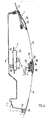
- Fig. 1 eine schematisch dargestellte Tür mit den durchgeführten Horizontal- und Vertikalschnitten,
- Fig. 2 einen Horizontalschnitt durch die Tür im Scharnierbereich gemäß der Linie II-II der Fig. 1,
- Fig. 3 einen Horizontalschnitt durch die Tür oberhalb des unteren Scharniers gemäß der Linie III-III der Fig. 4,
- Fig. 4 einen Vertikalschnitt durch die Tür gemäß der Linie IV-IV der Fig. 1,
- Fig. 5 einen Vertikalschnitt durch die Tür im Bereich der Türunterkante gemäß der Linie V-V der Fig. 1,
- Fig. 6 einen Horizontalschnitt durch die Tür im Bereich der Rammschutzleiste gemäß der Linie VI-VI der Fig. 1,
- Fig. 7 eine Exposionsdarstellung der Tür mit ihren Einzelelementen, und
- Fig. 8 einen Horizontalschnitt durch die Tür im Bereich des Schlosses nach der Linie VIII-VIII der Fig. 1.
- 1 is a schematically illustrated door with the horizontal and vertical sections,
- 2 is a horizontal section through the door in the hinge area along the line II-II of FIG. 1,
- 3 is a horizontal section through the door above the lower hinge along the line III-III of FIG. 4,
- 4 shows a vertical section through the door according to line IV-IV of FIG. 1,
- 5 shows a vertical section through the door in the region of the lower edge of the door according to the line VV of FIG. 1,
- 6 shows a horizontal section through the door in the area of the crash protection strip according to line VI-VI of FIG. 1,
- Fig. 7 is an exploded view of the door with its individual elements, and
- 8 is a horizontal section through the door in the area of the lock along the line VIII-VIII of FIG. 1st
Das Türsystem umfasst im wesentlichen zwei Baugruppen, wobei die erste Türbaugruppe einen Basiskörper 1 umfasst, dessen Einzelteile stoffschlüssig miteinander verbunden sind. Diese Einzelteile bestehen im wesentlichen aus einem Türrahmen 2, einem Querträger 3, einer Scharniersäule 4, einer Schloßsäule 5, einem oberen Türaußenteil 6 und einem Türschachtträger 7. Die zweite Türbaugruppe umfasst im wesentlichen ein Türinnenteil 8 und ein unteres Türaußenteil 9, das in einer Längsebene X-X vom oberen Türaußenteil 6 getrennt ist. Die Verbindung dieser zweiten Türbaugruppe mit der ersten Türbaugruppe erfolgt über eine lösbare Befestigung. Zwischen den Türteilen 8 und 6, 9 ist am Querträger 9 eine Fensterhebereinrichtung 10 und in dieser eine Scheibe 11 gehalten.The door system essentially comprises two assemblies, the first door assembly comprising a
Der Basiskörper 1 der ersten Türbaugruppe bildet eine stabile nach außen hin offene Tragstruktur. Sie ist zusammengesetzt aus dem Türrahmen 2, an dem die weiteren Einzelteile 3 bis 7 des Türsystems befestigt sind. So ist am vornliegenden Schenkel 12 des Türrahmens 2 die Scharniersäule 4 befestigt, welche zwei zu einem Kastenträger verbundene Halbschalen 13 und 14 umfasst. Innerhalb der Säule 4 ist eine Verstärkung 15 zur Haltung eines Scharniers 16 vorgesehen. Ein Halteschenkel 17 der Halbschale 13 ist über seinen Verbindungsort 18 an der innenliegenden Halbschale 14 hinausgeführt und mit einer inneren Halbschale 19 des Querträgers 3 sowie mit dem Türrahmen 2 verbunden, wogegen die äußere Halbschale 20 des Querträgers 3 an den beiden Schenkeln 12 und 21 abgestützt ist.Der Querträger 3 dient zur Aufnahme der Fensterhebereinrichtung 10.The
Mit dem Schenkel 21 des Türrahmens 2 und der inneren Halbschale 19 des Querträgers ist desweiteren die Schloßsäule 5 verbunden. Ein Schließzylinder 22 ist zwischen dem oberen Türaußenteil 6 und der Schloßsäule 5, die einschalig ausgeführt ist, gehalten. Ein Schließkeil 23 des Schlosses ist in Fig. 8 angedeutet.With the
Nachdem diese Einzelteile wie Scharniersäule 4, Schloßsäule 5 und Querträger 3 stoffschlüssig mit dem Türrahmen 2 verbunden sind, wird an das obere Türaußenteil 6 der Türschachtträger 7 angesetzt. Dieser besteht im wesentlichen aus zwei miteinander verbundenen Halbschalen 24 und 25, wobei die äußere Halbschale flächig an der Innenseite des oberen Türaußenteils 6 geklebt ist. Dieses Türaußenteil 6 sowie der Türschachtträger 7 sind endseitig ebenfalls stoffschlüssig mit dem Türrahmen 2 verbunden und bilden eine einteilige Baueinheit mit diesem und den anderen Türeinzelteilen 3 bis 5. Die Baueinheit ist von beiden Seiten her zugänglich, sc daß eine Montage von in der Tür liegenden Baugruppen, z.B. der Fensterhebereinrichtung 10, einfach möglich wird.After these individual parts such as
Nach dem Einbau dieser Aggregatteile wird die Tür durch die zweite Baugruppe gemeinsam durch: das Türinnenteil 8 und das untere Türaußenteil 9 kapselnd umschlossen. Das Türinnenteil 8 besteht vorzugsweise aus einer Kunststoffschale und wird mit dem unteren, ebenfalls aus Kunststoff bestehenden Türaußenteil 9 über Schraubmittel lösbar verbunden. Hierzu weist das untere Türaußenteil 9 eine angeformte Randleiste 26 auf, die eine umlaufende Anlagefläche 27 für das Türinnenteil 8 bildet und die Befestigungsmuttern 28 oder dergleichen Mittel zum Festsetzen der Schrauben 41 aufweist. Auch kann eine Dichtung in der Leiste 26 vorgesehen sein. Insbesondere ist die Randleiste 26 in einem horizontalen Befestigungsabschnitt 29 und vertikalen Befestigungsabschnitten 30 und 31 vorgesehen, was in Fig. 7 näher dargestellt ist.After installing these unit parts, the door is encapsulated by the second assembly by: encapsulating the
Das untere lösbare Türaußenteil 9 ist vom fest verbundenen oberen Türaußenteil 6 etwa im Bereich der größten Fahrzeugbreite in Längsrichtung geteilt ausgeführt. Über eine Halteeinrichtung 32, die aus zwei ineinandergreifenden U-profilförmigen Verbindungsleisten 33, 34 besteht, wird eine quasi formschlüssige Verbindung geschaffen. Zwischen diesen Leisten kann eine elastische Dichtung, z.B. aus Gummi oder dergleichen, angeordnet sein. Unterhalb dieser Halteeinrichtung 32, unmittelbar anschließend an die Verbindungsleiste 34, ist eine nach innen verlagerte Rinne 35 vorgesehen. In dieser ist eine aus einem biegesteifen Träger bestehende Rammschutzleiste 37 gehalten, die nach außen hin über eine elastische Leiste 38 abgedeckt ist. Diese erstreckt sich über die Stoßkante 36 der beiden Türaußenteile 6 und 9 hinaus (Fig. 4). Die Rammschutzleiste 37 ist jeweils endseitig mit den Türteilen 8 und 9 verschraubt und stützt sich am Türbasiskörper ab.The lower detachable outer door part 9 is divided from the firmly connected upper
Das Türinnenteil 8 weist in Höhe des Querträgers 3 Abstandsnocken 39 auf, in denen durch die Halbschale 19 des Querträgers 3 gezogene Schrauben 40 zum Festlegen des Türinnenteils 8 befestigt werden.The
Die Bauteile der ersten Türbaugruppe sind vorzugsweise so aufgebaut und weisen solche Schweißpunkte auf, daß eine Roboter-Montage und -Schweißung möglich wird. So werden zuerst die zweischalig ausgeführten Bauteile wie die Scharniersäule 4, der Querträger 3 und der Türschachtträger 7 sowie das obere Türaußenteil 6 und die Schloßsäule 5 stoffschlüssig mit dem Türrahmen 2 verbunden. Durch die von den vertikalen Schenkeln 12 und 21 des Türrahmens 2 seitlich begrenzte Innen-und Außenöffnung der Tür sind die Einbauaggregate (Fensterheber 10, Scheibe 11) am Querträger 3 montierbar. Das komplettierte Türinnenteil 8 wird zusammen mit dem unteren Türaußenteil 9 verbunden und durch die Rammschutzleiste 37 ergänzt zusammengebaut.The components of the first door assembly are preferably constructed and have such welding spots that a robot assembly and welding is possible. So be first the two-shell components such as the
Claims (14)
Applications Claiming Priority (2)
| Application Number | Priority Date | Filing Date | Title |
|---|---|---|---|
| DE3537303 | 1985-10-19 | ||
| DE19853537303 DE3537303A1 (en) | 1985-10-19 | 1985-10-19 | DOOR SYSTEM FOR MOTOR VEHICLES |
Publications (3)
| Publication Number | Publication Date |
|---|---|
| EP0222990A2 true EP0222990A2 (en) | 1987-05-27 |
| EP0222990A3 EP0222990A3 (en) | 1987-08-05 |
| EP0222990B1 EP0222990B1 (en) | 1988-12-28 |
Family
ID=6284002
Family Applications (1)
| Application Number | Title | Priority Date | Filing Date |
|---|---|---|---|
| EP86111724A Expired EP0222990B1 (en) | 1985-10-19 | 1986-08-25 | Door system for motor vehicles |
Country Status (4)
| Country | Link |
|---|---|
| US (1) | US4704822A (en) |
| EP (1) | EP0222990B1 (en) |
| JP (1) | JPS6299209A (en) |
| DE (2) | DE3537303A1 (en) |
Cited By (5)
| Publication number | Priority date | Publication date | Assignee | Title |
|---|---|---|---|---|
| EP0476351A1 (en) * | 1990-08-30 | 1992-03-25 | Schade Kg | Vehicle door |
| FR2695891A1 (en) * | 1992-09-24 | 1994-03-25 | Peugeot | Protective assembly for vehicle structural components - is formed from lateral reinforcement components, which slide one over the other on frontal shock loading |
| EP0601286A1 (en) * | 1992-12-11 | 1994-06-15 | YMOS AKTIENGESELLSCHAFT Industrieprodukte | Motor vehicle door |
| EP0630775A1 (en) * | 1993-06-26 | 1994-12-28 | VAW Aluminium AG | Vehicle door |
| US5822927A (en) * | 1993-06-26 | 1998-10-20 | Vaw Aluminium Ag | Motor vehicle door |
Families Citing this family (22)
| Publication number | Priority date | Publication date | Assignee | Title |
|---|---|---|---|---|
| US4743062A (en) * | 1986-09-19 | 1988-05-10 | The Dow Chemical Company | Vehicle door assembly |
| US4845894A (en) * | 1987-08-25 | 1989-07-11 | The Budd Company | Method of mounting an outer skin to an inner panel of a vehicle door |
| DE3728776C1 (en) * | 1987-08-28 | 1989-03-02 | Daimler Benz Ag | Motor-vehicle door with a longitudinally divided outer panel |
| JPH0260824A (en) * | 1988-08-25 | 1990-03-01 | Honda Motor Co Ltd | On-vehicle door structure |
| US5117549A (en) * | 1989-02-21 | 1992-06-02 | Davidson Textron Inc. | Automotive door panels and method of assembly therefor |
| FR2643860B1 (en) * | 1989-03-03 | 1991-06-21 | Rockwell Cim | SUPPORT FOR PRE-ASSEMBLED AND PRESET EQUIPMENT FOR A MOTOR VEHICLE DOOR AND DOOR COMPRISING THE SAME |
| US5095659A (en) * | 1989-05-02 | 1992-03-17 | Atoma International, A Magna International Company | Automobile door modular assembly |
| US4984389A (en) * | 1989-05-02 | 1991-01-15 | Atoma International, A Magna International Company | Automobile door with flush mounted glass |
| FR2648762B1 (en) * | 1989-06-27 | 1991-10-18 | Rockwell Cim | INTERIOR TRIM PANEL OF A VEHICLE DOOR, CORRESPONDING DOOR, AND METHOD OF MOUNTING THE DOOR |
| IT1237607B (en) * | 1989-11-21 | 1993-06-08 | Fiat Auto Spa | HINGE DEVICE FOR A VEHICLE SIDE DOOR |
| CA2054577C (en) * | 1991-01-25 | 1996-03-12 | Larry Holt | Module for vehicle door |
| US5787645A (en) * | 1992-07-06 | 1998-08-04 | Ymos Aktiengesellschaft Industrieprodukte | Motor vehicle door frame |
| DE4422745B4 (en) * | 1994-06-29 | 2005-10-06 | ED. SCHARWäCHTER GMBH | Motor vehicle door |
| JP3410372B2 (en) * | 1998-08-31 | 2003-05-26 | アイシン精機株式会社 | Vehicle door lock operation system and vehicle door provided with the door lock operation system |
| US6390533B1 (en) * | 1998-08-31 | 2002-05-21 | Honda Giken Kogyo Kabushiki Kaisha | Synthetic resin vehicle door outer panel |
| DE19946307A1 (en) * | 1999-09-28 | 2001-04-12 | Meritor Automotive Gmbh | Vehicle door and assembly process |
| US6508035B1 (en) * | 2000-07-25 | 2003-01-21 | Alcoa Inc. | Ultra-lightweight thin sliding door for a vehicle |
| US7363750B2 (en) * | 2000-07-25 | 2008-04-29 | Alcoa Inc. | Sliding vehicle door with a moveable window assembly |
| US20060264554A1 (en) * | 2005-05-17 | 2006-11-23 | Arnold Lustiger | Fiber reinforced polypropylene composite door core modules |
| US20080098655A1 (en) * | 2006-10-31 | 2008-05-01 | Jeffrey Valentage | Integrated bracket for mounting pulley |
| JP6123743B2 (en) * | 2014-07-04 | 2017-05-10 | トヨタ自動車株式会社 | Vehicle door structure |
| LU92949B1 (en) | 2016-01-15 | 2017-08-10 | Mdh Hologram S A | Apparatus for viewing three-dimensional images and videos in real environments |
Citations (5)
| Publication number | Priority date | Publication date | Assignee | Title |
|---|---|---|---|---|
| DE2127724A1 (en) * | 1971-06-04 | 1972-12-07 | Ford-Werke AG, 5000 Köln | Vehicle door, in particular for passenger vehicles |
| DE3004897A1 (en) * | 1980-02-09 | 1981-08-27 | Audi Nsu Auto Union Ag, 7107 Neckarsulm | VEHICLE DOOR, ESPECIALLY SIDE DOOR OF A CAR |
| WO1981003467A1 (en) * | 1980-06-09 | 1981-12-10 | Budd Co | Plastic door for an automobile |
| DE3104681A1 (en) * | 1980-02-11 | 1981-12-24 | The Budd Co., 48084 Troy, Mich. | PLASTIC DOOR FOR A MOTOR VEHICLE |
| DE3209052A1 (en) * | 1982-03-12 | 1983-09-29 | Brose Fahrzeugteile GmbH & Co KG, 8630 Coburg | Vehicle doors |
Family Cites Families (5)
| Publication number | Priority date | Publication date | Assignee | Title |
|---|---|---|---|---|
| GB1392710A (en) * | 1971-08-21 | 1975-04-30 | Gkn Sankey Ltd | Doors for vehicles |
| GB2108912B (en) * | 1981-10-23 | 1985-05-22 | Fiat Auto Spa | Method of constructing a motor vehicle door |
| DE3217640A1 (en) * | 1982-03-12 | 1983-11-17 | Brose Fahrzeugteile GmbH & Co KG, 8630 Coburg | VEHICLE DOOR |
| JPS59171714A (en) * | 1983-03-04 | 1984-09-28 | Honda Motor Co Ltd | Door for automobile |
| DE3666190D1 (en) * | 1985-06-25 | 1989-11-23 | Mazda Motor | Vehicle door structure having plastic door panel |
-
1985
- 1985-10-19 DE DE19853537303 patent/DE3537303A1/en not_active Withdrawn
-
1986
- 1986-08-25 EP EP86111724A patent/EP0222990B1/en not_active Expired
- 1986-08-25 DE DE8686111724T patent/DE3661506D1/en not_active Expired
- 1986-10-17 JP JP61245624A patent/JPS6299209A/en active Pending
- 1986-10-20 US US06/920,455 patent/US4704822A/en not_active Expired - Fee Related
Patent Citations (5)
| Publication number | Priority date | Publication date | Assignee | Title |
|---|---|---|---|---|
| DE2127724A1 (en) * | 1971-06-04 | 1972-12-07 | Ford-Werke AG, 5000 Köln | Vehicle door, in particular for passenger vehicles |
| DE3004897A1 (en) * | 1980-02-09 | 1981-08-27 | Audi Nsu Auto Union Ag, 7107 Neckarsulm | VEHICLE DOOR, ESPECIALLY SIDE DOOR OF A CAR |
| DE3104681A1 (en) * | 1980-02-11 | 1981-12-24 | The Budd Co., 48084 Troy, Mich. | PLASTIC DOOR FOR A MOTOR VEHICLE |
| WO1981003467A1 (en) * | 1980-06-09 | 1981-12-10 | Budd Co | Plastic door for an automobile |
| DE3209052A1 (en) * | 1982-03-12 | 1983-09-29 | Brose Fahrzeugteile GmbH & Co KG, 8630 Coburg | Vehicle doors |
Cited By (5)
| Publication number | Priority date | Publication date | Assignee | Title |
|---|---|---|---|---|
| EP0476351A1 (en) * | 1990-08-30 | 1992-03-25 | Schade Kg | Vehicle door |
| FR2695891A1 (en) * | 1992-09-24 | 1994-03-25 | Peugeot | Protective assembly for vehicle structural components - is formed from lateral reinforcement components, which slide one over the other on frontal shock loading |
| EP0601286A1 (en) * | 1992-12-11 | 1994-06-15 | YMOS AKTIENGESELLSCHAFT Industrieprodukte | Motor vehicle door |
| EP0630775A1 (en) * | 1993-06-26 | 1994-12-28 | VAW Aluminium AG | Vehicle door |
| US5822927A (en) * | 1993-06-26 | 1998-10-20 | Vaw Aluminium Ag | Motor vehicle door |
Also Published As
| Publication number | Publication date |
|---|---|
| EP0222990A3 (en) | 1987-08-05 |
| EP0222990B1 (en) | 1988-12-28 |
| US4704822A (en) | 1987-11-10 |
| DE3661506D1 (en) | 1989-02-02 |
| DE3537303A1 (en) | 1987-04-23 |
| JPS6299209A (en) | 1987-05-08 |
Similar Documents
| Publication | Publication Date | Title |
|---|---|---|
| EP0222990B1 (en) | Door system for motor vehicles | |
| DE10023193B4 (en) | Vehicle body for a front end of a motor vehicle | |
| DE3104681C2 (en) | Motor vehicle door made of plastic | |
| EP3710342B1 (en) | Side sill arrangement of a body of an electrically operable motor vehicle | |
| EP0613798B1 (en) | Vehicle door, especially for motor vehicles | |
| EP0253967B1 (en) | Vehicle bumper | |
| EP0601286B1 (en) | Motor vehicle door | |
| EP0152110B1 (en) | Edge cover strip for a glass pane, in particular for a door wing made completely of glass | |
| DE102005044283A1 (en) | Motor vehicle body with an adapter carrier for a roof module, adapter carrier therefor, and method for their preparation | |
| EP0786398A1 (en) | Motor vehicle with body structure and assembling jig | |
| DE10114018B4 (en) | Receiving and connecting device for a bow / rear bumper of a motor vehicle | |
| WO2020120076A1 (en) | Energy storage underbody for a motor car body-in-white | |
| DE19629060A1 (en) | Roof rail arrangement for motor vehicles | |
| EP1911662A1 (en) | Vehicle body base and a platform system | |
| DE202007005265U1 (en) | Mounting plate for door closer, has receiving side opposite to mounting side for receiving door closer, where closer is fastened with mounting side at receiving body such as door frame, where plate is made steel material | |
| EP1253045B1 (en) | Apparatus for attaching a mounting element to a vehicle body structur | |
| DE2638440C3 (en) | Roll-over protective frames for motor vehicles | |
| DE602004003082T2 (en) | A method of assembling a motor vehicle body with doors, vehicle body made according to the method, and doors for such a vehicle body | |
| DE19727010A1 (en) | Motor vehicle door manufacture window frame module | |
| DE4007391C2 (en) | Mounting flange for a cover strip | |
| EP1346879B1 (en) | Profile for a side sill of a motor vehicle | |
| DE10200516A1 (en) | Vehicle door or flap | |
| EP0373143B1 (en) | Tank, especially a fuel tank for motor vehicles | |
| DE19732700B4 (en) | Frame arrangement for a cover part of a vehicle roof | |
| DE19524506A1 (en) | Front wing reinforcing structure in vehicle body |
Legal Events
| Date | Code | Title | Description |
|---|---|---|---|
| PUAI | Public reference made under article 153(3) epc to a published international application that has entered the european phase |
Free format text: ORIGINAL CODE: 0009012 |
|
| AK | Designated contracting states |
Kind code of ref document: A2 Designated state(s): DE FR GB IT NL SE |
|
| PUAL | Search report despatched |
Free format text: ORIGINAL CODE: 0009013 |
|
| AK | Designated contracting states |
Kind code of ref document: A3 Designated state(s): DE FR GB IT NL SE |
|
| 17P | Request for examination filed |
Effective date: 19870818 |
|
| 17Q | First examination report despatched |
Effective date: 19880506 |
|
| ITF | It: translation for a ep patent filed |
Owner name: DE DOMINICIS & MAYER S.R.L. |
|
| GRAA | (expected) grant |
Free format text: ORIGINAL CODE: 0009210 |
|
| AK | Designated contracting states |
Kind code of ref document: B1 Designated state(s): DE FR GB IT NL SE |
|
| REF | Corresponds to: |
Ref document number: 3661506 Country of ref document: DE Date of ref document: 19890202 |
|
| GBT | Gb: translation of ep patent filed (gb section 77(6)(a)/1977) | ||
| ET | Fr: translation filed | ||
| PLBE | No opposition filed within time limit |
Free format text: ORIGINAL CODE: 0009261 |
|
| STAA | Information on the status of an ep patent application or granted ep patent |
Free format text: STATUS: NO OPPOSITION FILED WITHIN TIME LIMIT |
|
| 26N | No opposition filed | ||
| PGFP | Annual fee paid to national office [announced via postgrant information from national office to epo] |
Ref country code: SE Payment date: 19900724 Year of fee payment: 5 |
|
| PGFP | Annual fee paid to national office [announced via postgrant information from national office to epo] |
Ref country code: FR Payment date: 19900727 Year of fee payment: 5 |
|
| PGFP | Annual fee paid to national office [announced via postgrant information from national office to epo] |
Ref country code: GB Payment date: 19900813 Year of fee payment: 5 |
|
| PGFP | Annual fee paid to national office [announced via postgrant information from national office to epo] |
Ref country code: DE Payment date: 19900822 Year of fee payment: 5 |
|
| ITTA | It: last paid annual fee | ||
| PGFP | Annual fee paid to national office [announced via postgrant information from national office to epo] |
Ref country code: NL Payment date: 19900831 Year of fee payment: 5 |
|
| PG25 | Lapsed in a contracting state [announced via postgrant information from national office to epo] |
Ref country code: GB Effective date: 19910825 |
|
| PG25 | Lapsed in a contracting state [announced via postgrant information from national office to epo] |
Ref country code: SE Effective date: 19910826 |
|
| PG25 | Lapsed in a contracting state [announced via postgrant information from national office to epo] |
Ref country code: NL Effective date: 19920301 |
|
| NLV4 | Nl: lapsed or anulled due to non-payment of the annual fee | ||
| GBPC | Gb: european patent ceased through non-payment of renewal fee | ||
| PG25 | Lapsed in a contracting state [announced via postgrant information from national office to epo] |
Ref country code: FR Effective date: 19920430 |
|
| PG25 | Lapsed in a contracting state [announced via postgrant information from national office to epo] |
Ref country code: DE Effective date: 19920501 |
|
| REG | Reference to a national code |
Ref country code: FR Ref legal event code: ST |
|
| EUG | Se: european patent has lapsed |
Ref document number: 86111724.0 Effective date: 19920306 |
|
| PG25 | Lapsed in a contracting state [announced via postgrant information from national office to epo] |
Ref country code: IT Free format text: LAPSE BECAUSE OF NON-PAYMENT OF DUE FEES;WARNING: LAPSES OF ITALIAN PATENTS WITH EFFECTIVE DATE BEFORE 2007 MAY HAVE OCCURRED AT ANY TIME BEFORE 2007. THE CORRECT EFFECTIVE DATE MAY BE DIFFERENT FROM THE ONE RECORDED. Effective date: 20050825 |