EP0222652A1 - Kraft- und Torsionsmessvorrichtung und ihre Anwendung an einer Fühler- oder Greifeinrichtung - Google Patents
Kraft- und Torsionsmessvorrichtung und ihre Anwendung an einer Fühler- oder Greifeinrichtung Download PDFInfo
- Publication number
- EP0222652A1 EP0222652A1 EP86402335A EP86402335A EP0222652A1 EP 0222652 A1 EP0222652 A1 EP 0222652A1 EP 86402335 A EP86402335 A EP 86402335A EP 86402335 A EP86402335 A EP 86402335A EP 0222652 A1 EP0222652 A1 EP 0222652A1
- Authority
- EP
- European Patent Office
- Prior art keywords
- branches
- gauges
- branch
- measurement
- symmetry
- Prior art date
- Legal status (The legal status is an assumption and is not a legal conclusion. Google has not performed a legal analysis and makes no representation as to the accuracy of the status listed.)
- Granted
Links
Images


Classifications
-
- G—PHYSICS
- G01—MEASURING; TESTING
- G01L—MEASURING FORCE, STRESS, TORQUE, WORK, MECHANICAL POWER, MECHANICAL EFFICIENCY, OR FLUID PRESSURE
- G01L5/00—Apparatus for, or methods of, measuring force, work, mechanical power, or torque, specially adapted for specific purposes
- G01L5/22—Apparatus for, or methods of, measuring force, work, mechanical power, or torque, specially adapted for specific purposes for measuring the force applied to control members, e.g. control members of vehicles, triggers
- G01L5/226—Apparatus for, or methods of, measuring force, work, mechanical power, or torque, specially adapted for specific purposes for measuring the force applied to control members, e.g. control members of vehicles, triggers to manipulators, e.g. the force due to gripping
-
- B—PERFORMING OPERATIONS; TRANSPORTING
- B25—HAND TOOLS; PORTABLE POWER-DRIVEN TOOLS; MANIPULATORS
- B25J—MANIPULATORS; CHAMBERS PROVIDED WITH MANIPULATION DEVICES
- B25J13/00—Controls for manipulators
- B25J13/08—Controls for manipulators by means of sensing devices, e.g. viewing or touching devices
- B25J13/085—Force or torque sensors
-
- G—PHYSICS
- G01—MEASURING; TESTING
- G01L—MEASURING FORCE, STRESS, TORQUE, WORK, MECHANICAL POWER, MECHANICAL EFFICIENCY, OR FLUID PRESSURE
- G01L5/00—Apparatus for, or methods of, measuring force, work, mechanical power, or torque, specially adapted for specific purposes
- G01L5/16—Apparatus for, or methods of, measuring force, work, mechanical power, or torque, specially adapted for specific purposes for measuring several components of force
- G01L5/161—Apparatus for, or methods of, measuring force, work, mechanical power, or torque, specially adapted for specific purposes for measuring several components of force using variations in ohmic resistance
- G01L5/1627—Apparatus for, or methods of, measuring force, work, mechanical power, or torque, specially adapted for specific purposes for measuring several components of force using variations in ohmic resistance of strain gauges
Definitions
- the invention relates to a sensor for measuring forces and torques remarkable in particular for its small size and for its modular nature.
- the invention also relates to a probe and a gripper using one or more sensors of this type.
- wrist sensors are generally either sensitive to temperature, or designed so that decoupling between the three forces and the three measured couples is delicate and requires very complex calculations.
- French patent application No. 2,520,279 describes a device making it possible to determine a force and two torques for each of the fingers of the gripper.
- French Patent No. 2,375,962 describes a two-finger gripper each comprising three blades located in orthogonal planes and working in flexion, each blade being equipped with strain gauges. However, only three measurements are made on each of the fingers, which in practice limits the applications of this device to the same cases as for the wrist sensors.
- the main object of the present invention is a sensor for measuring forces and torques making it possible to measure three forces and two or three torques in a small volume and in particular with a very small footprint in the plane orthogonal to the axis of symmetry of the sensor, which allows in particular the insertion of such a sensor directly into the finger of a gripper.
- the invention also relates to a sensor for measuring forces and torques having a good decoupling between the quantities measured and whose modular nature allows the production of grippers in which each of the fingers is equipped with a sensor ensuring at will the number of measurements desired.
- a sensor for measuring forces and torques comprises two U-shaped parts, each comprising two measuring branches connected to their base by a intermediate branch, the branches of the same part passing through a plane of symmetry containing an axis of longitudinal symmetry Z, said parts being placed in opposite direction with said planes of symmetry of each part orthogonal to one another, and their axes of symmetry combined, the ends of the measurement branches of each of said parts being connected to the intermediate branch of the other part by two cylindrical connections each allowing rotation and translation along the same axis X, Y orthogonal to the axis Z and parallel to said plane of symmetry of said other part, each of the measurement branches being able to deform in said plane of symmetry of the part to which this branch belongs, measurement gauges constraints being arranged on these measurement branches so as to measure the forces exerted in the three directions X, Y and Z and the moments of the couples around the directions X and Y.
- each of the measurement branches has two parallel and opposite plane faces, or thogonal to said plane of symmetry of the part to which this branch belongs and parallel to said longitudinal axis of symmetry Z; the strain measurement gauges are placed on these faces.
- strain measurement gauges are preferably placed two by two on the opposite faces of one of the measurement branches of each part. Preferably, and to optimize the sensitivity, they are placed respectively near the base and the end of this branch.
- the forces exerted in the direction Z are preferably measured by means of two strain measurement gauges arranged on the opposite faces of one of the measurement branches of one of the parts and of two other measurement gauges. of stresses arranged on the opposite faces of one of the measurement branches of the other part.
- the moments of the couples exerted around the directions X and Y are preferably measured by means of four strain measurement gauges arranged on the opposite faces of two measurement branches of each of the parts, substantially at the same level along the Z axis. .
- each of the cylindrical connections comprises a cylindrical pin passing through the end of one of the measurement branches and of the ears formed on either side of this end on the intermediate branch of the U-shaped part to which this branch of measurement does not belong, an elastic centering member being mounted on the pin between the end of the measurement branch and each of the ears.
- the intermediate branch of one of said parts supports a gripping part in a rotary manner around the axis Z, return means being provided to urge the gripping part towards an angular position of rest around of the Z axis, measurement means being interposed between this part and the gripping part to measure this rotation.
- the measurement means can in particular be magnetic or optical.
- the intermediate branch of one of the U-shaped pieces rigidly supports a flexible piece in torsion around the axis Z, at least one pair of strain gauges being disposed on this working piece in torsion.
- a probe capable of following the contour of an object by contact of this object with the end of a rod mounted on a support comprises, between the rod and the support, a sensor made of as previously defined, the sensor parts being fixed respectively by their intermediate branches on the support and on the probe rod.
- the invention also relates to a gripping device with at least two gripping fingers each comprising a gripping end and a base by which the fingers are movably mounted on a support, characterized in that each gripping finger comprises a sensor, said U-shaped parts of each sensor being fixed respectively by their intermediate branches on the base and on the gripping end of the finger to which it belongs.
- FIG. 1 represents the basic module of the sensor according to the invention, which makes it possible to measure the forces applied along three orthogonal axes X, Y and Z, as well as the moment of the couples around the axes X and Y.
- This module generally designated by the reference 10, will now be described in detail with reference to FIG. 1.
- the module 10 comprises two parts 12a and 12b, monolithic and each having approximately the shape of a U. These parts are preferably identical. However, they can also be slightly different as shown in Figure 1.
- the part 12a comprises an intermediate branch 14a and two parallel measuring branches 16a and 18a, connected by their base to the branch 14a.
- the part 12b comprises an intermediate branch 14b and two parallel measuring branches 16b and 18b connected by their base to the branch 14b.
- each of the parts 12a and 12b has a plane of symmetry passing through each of the three branches which constitute it, as well as a longitudinal axis of symmetry.
- Each of the measurement branches 16a, 18a and 16b, 18b has over the major part of its length a uniform rectangular section.
- the parallel and opposite plane faces corresponding to the longest sides of this rectangular section are orthogonal to the plane of symmetry of the corresponding part and parallel to the longitudinal axis of symmetry of this part.
- the internal face will be the face of each of the measurement branches facing the axis of symmetry of the corresponding part and the external face the opposite face of this same branch.
- each of the measurement branches 16a, 18a and 16b, 18b behaves like a beam capable of bending in the plane of symmetry of the part to which it belongs, while being relatively rigid in a direction orthogona the to this plane and to the axis of symmetry of the part.
- the parts 12a and 12b are placed in the opposite direction or head to tail, so that their axes of symmetry are merged and their planes of symmetry defined above are orthogonal.
- the axes X, Y and Z are defined so that the axis Z corresponds to the axis of symmetry common to the two parts 12a and 12b, the axes X and Y being perpendicular to the axis Z and contained respectively in the plane of symmetry of the part 12a and in the plane of symmetry of the part 12b.
- the parts 12a and 12b are fitted one inside the other, so that the ends of the branches 16b and 18b are opposite the branch 14a and that the ends of the branches 16a and 18a are in face of branch 14b.
- the parts 12a and 12b are interconnected by four cylindrical connections, each allowing limited rotation and translation.
- the other two cylindrical connections are obtained by means of cylindrical pins 20b and 22b which pass respectively through the ends of the branches 16b and 18b as well as ears formed on either side of these ends on the intermediate branch 14a.
- the axes of these pins 20b and 22b are parallel to each other as well as to the axis X defined above.
- Elastic washers 24b and 26b are also placed on the pins 20b and 22b between the ends of the branches 16b and 18b and the ears formed on the branch 14a. A relative displacement between the ends of the branches 16b and 18b and the intermediate branch 14a as well as an automatic centering of these branches are thus obtained.
- the elastic washers 24a, 26a and 24b, 26b could be replaced by any other elastic centering device with low hysteresis such as springs or metal washers.
- the application of a relative force parallel to the axis X between the parts 12a and 12b has the effect of making the branches 16a and 18a of the part 12a bend in this direction, while there is practically no bending of the branches 16b and 18b of the part 12b, the offset along X produced between the parts 12a and 12b under the effect of the bending of the branches 16a and 18a being compensated by the elastic washers 24b and 26b.
- the application of a force in the longitudinal direction Z between the parts 12a and 12b has the effect of making each of the branches 16a, 18a, 16b and 18b work simultaneously in traction or in compression.
- one and the other of the branches 16a and 18a of the part 12a (the branch 18a in FIG. 1) is fitted with a first series of four gauges J1, J2 , J′1, J′2 allowing to measure the bending of this branch. More precisely, the gauges J1 and J2 are placed on the internal face of the branch 18a and the gauges J′1 and J′2 are placed on the external face of this same branch, the gauges J1 and J′1 being placed near the base of this branch while the gauges J2 and J′2 are placed near its end.
- gauges K1, K2, K′1 and K′2 are mounted on one of the measurement branches of the part 12b (the branch 18b in FIG. 1), in order to measure the bending of this branch under the effect of a force Fy in the direction Y.
- the gauges K1 and K2 are mounted on the internal face of the branch 18b and the gauges K′1 and K′2 on the external face of this same branch.
- the gauges K1 and K′1 are placed close to the end of the branch 18b while the gauges K2 and K′2 are close to the base of this branch.
- the gauges J1, J2, J′1, J′2 and K1, K2, K′1, K′2 can be relatively few gauges sensitive such as gauges with film weft.
- the gauges J9 and J′9 are mounted respectively on the external face and on the internal face of the branch 16a, near the end of the latter and the gauges K9 and K′9 are placed respectively on the external face and on the internal face of the branch 16b, near the base thereof.
- the sensitive axes of the gauges J9 and J′9 mounted on the branch 16a are orthogonal to the sensitive axes of the gauges K9 and K′9 mounted on the branch 16b.
- the sensitive axes of the gauges J9 and J′9 are oriented along Z
- the sensitive axes of the gauges K9 and K′9 are oriented along X.
- the sensitive axes of the gauges J9 and J′9 are oriented along Y
- the sensitive axes of the gauges K9 and K′9 are oriented along Z.
- the measurement of the moment Mx of this couple is made by means of a group of four gauges K3, K′3, K4, K′4 mounted two by two on each of these branches. More precisely, the gauges K3 and K′3 are mounted respectively on the internal face and on the external face of the branch 18b, approximately in the middle thereof, and the gauges K4 and K′4 are respectively mounted on the external face and on the internal face of the branch 16b, approximately in the middle of the latter.
- gauges J3, J′3, J ′, J′4 are mounted on the branches 16a and 18a of the part 12a to measure the moment My of the torque around the Y axis. More precise, the gauges J3 and J′3 are mounted respectively on the internal and external faces of the branch 18a, approximately in the middle of the latter and the gauges J4 and J′4 are mounted respectively on the external and internal faces of the branch 16a, approximately in the middle of it.
- the gauges J9, J′9, K′9; J3, J′3, J4, J′4 and K3, K′3, K4, K′4 are preferably gauges with good sensitivity such as semiconductor gauges.
- the gauges each constituting groups of gauges making it possible to measure the forces F X , F Y and F Z as well as the moments M X and M Y of the couples around the axes X and Y are mounted in identical electrical circuits, one of which is shown as an example in Figure 2.
- FIG. 2 shows more precisely the electrical circuit making it possible to measure the force F X in the direction X by means of the gauges J1 and J2, J′1 and J′2.
- these four gauges are connected to form a Wheastone bridge, the gauge J1 being connected between two terminals of the gauges J′1 and J′2 while the gauge J2 is connected to the two other terminals of the gauges J′1 and I 2.
- a voltage source V (or current I) is connected between the terminal common to the gauges J1 and J′2 and between the terminal common to the gauges J2 and J′1.
- the voltage measured by the device D (or respectively the current) between the terminals common to the gauges J1 and J′1 and the terminals common to the gauges J2 and J′2 is representative of the signal F X.
- a comparable circuit is formed with the gauges K1, K2, K′1 and K′2 to measure the signal F Y.
- the gauges K′1, K2, K1 and K′2 respectively replace the gauges J1, J2, J′1 and J′2 in FIG. 2.
- the electrical circuit making it possible to determine the force F Z in the direction Z is also identical to the circuit shown in FIG. 2, the gauges K9, K′9, J9 and J′9 respectively replacing the gauges J1, J2, J′1 and J′2.
- the measurement of the moment of the torque M Y around the Y axis is carried out using a circuit identical to that of FIG. 2, the gauges J1, J2, J′1 and J′2 being replaced respectively by the gauges J4, J′4 and J3 and J′3.
- the strain measurement gauges are arranged at substantially the same distance from the origin of the sensor.
- the moment M Z of the torque applied around the longitudinal axis Z of the sensor can also be determined.
- the module extends along its longitudinal axis Z, in the form of a cylindrical rod 28.
- the parts 12a and 12b being identical, the rod 28 is fixed as the case may be, on the branch 14a of the part 12a, or on the branch 14b of the part 12b.
- the rod 28 rotatably supports, thanks to bearings 30, a gripping part 32.
- the angular position of this part 32 around the axis Z is determined at rest by a return spring 34 interposed between this part 32 and the part 12a or 12b of the module 10 supporting the rod 28.
- This relative rotation can be measured using various known means and in particular using an optical or magnetic system (not shown).
- this measurement is carried out by means of a magnetic system constituted by a differential magneto-resistance 36 attached to a magnet 38 mounted on a support 40 itself fixed on the rod 28 in the immediate vicinity of the module 10.
- a piece of soft iron 42 normally placed facing the magneto-resistance 36 when no torque is applied around the Z axis, we can thus measure the moment M Z.
- an electrical circuit such as that shown in Figure 5 can be used.
- the magneto-resistance 36 with which two resistors R1 and R2 are associated to form a Wheastone bridge.
- a voltage is applied between the common terminal to the resistor R1 and to the magneto-resistance 36 and the common terminal to the resistor R2 and to the magneto-resistance 36 by means of a voltage source V (or possibly of current I for better noise immunity). It is thus possible to measure, using a device D, the voltage (or the current respectively) between the magneto-resistance 36 and the terminal common to the resistors R1 and R2, this voltage being representative of the moment M Z of the torque applied around the Z axis.
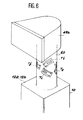
- FIG. 6 A second solution to the problem of measuring the moment M Z is represented in FIG. 6.
- this solution one interposed between one of the parts 12a and 12b of the module 10 and a gripping part 48b a metal part 60 working in torsion around the axis Z.
- strain gauges By bonding strain gauges to this part working in torsion and mounting these gauges in an electrical measurement circuit, we can determine in a known manner the moment of the torsional torque exerted on this part, that is to say the moment M Z.
- gauges T1, T2, T′1, T′2 are placed at the same level along Z on the part 60 and circumferentially distributed at 90 ° from one another around this room.
- the gauges T1, T′1 on the one hand and T2, T′2 on the other hand are located in diametrically opposite locations and oriented at 45 ° and in opposite directions relative to the Z axis.
- the moment M Z is measured.
- only two gauges such as the gauges T1, T′1 or T2, T′2 could however be used.
- This application relates to a gripper 44 essentially consisting of a support 46 on which are mounted two fingers 48 and 50.
- the fingers 48 and 50 could be articulated on the support 46. In the embodiment shown in FIG. 6, they remain constantly parallel to each other and move by sliding on the support 46, under the effect of a control device not shown.
- each of the fingers 48 and 50 has, between its base 48a, 50a res pectively and its gripping end 48b, 50b respectively a sensor for measuring forces and torques C1, C2 produced in accordance with the invention.
- the sensor C1 mounted in the finger 48 can be a sensor measuring three forces and two couples such as the basic module described above with reference to FIG. 1.
- the gripping part 48b constituting the end of this finger is then a cylindrical part mounted so as to be able to rotate freely around an axis coincident with the longitudinal axis of the sensor 10, along the Z axis.
- the moment of the torque applied around the Z axis is therefore always zero and justifies the absence of means used to measure this moment.
- the other finger 50 may on the contrary comprise a sensor C2 making it possible to measure three forces and three couples.
- the sensor C2 is then formed by the module 10, equipped for example with the magneto-resistance device described above with reference to FIGS. 3 and 4.
- the gripping end 50b of this finger 50 is then constituted by a part comprising for example a gripping surface having in section in the plane X, Y the shape of a V, as illustrated in FIG. 6.
- the gripping part 50b can pivot slightly around an axis coincident with the longitudinal axis Z of the sensor 10, in order to better adapt to the object than the we want to grasp.
- a clamp produced in the manner which has just been described with reference to FIG. 7 ensures the gripping of any object while allowing to know at all times the interaction components between this object and each of the fingers of the pliers.
- the invention is not limited to this application and also relates to the case where sensors according to the invention are introduced into each of the fingers of a clamp comprising three or more fingers.
- sensors according to the invention are introduced into each of the fingers of a clamp comprising three or more fingers.
- Such pliers will be used to solve more complex cases, for example when an object must be grasped at three points.
- the fingers or the entire clamp can then grasp an object without exerting unnecessary stress on the latter resulting from incorrect object-clamp positioning and without the object sliding on the surface on which it is placed.
- a sensor constituted by the module described above with reference to FIG. 1, possibly supplemented by the measurement of the torque around the Z axis in the manner described by way of example with reference to FIG. 3, is placed in a probe intended to follow the periphery of an object with contact.
- One of the two parts constituting the sensor is then fixed by its intermediate branch on a support constituted by a servo-carrying device such as a robot.
- the other part of the sensor also carries by its intermediate branch a rod extending along the longitudinal axis Z and terminated by a spherical part.
- the measurement of the forces and torques carried out by the sensor makes it possible to send to the carrier device or to the robot information that can be interpreted as a change of track instruction. jectory or orientation, so that the sphere remains subject to contact with the part to be followed.
- One of the uses of such a probe can consist in a self-adaptation of a robot having to perform work on the contour of a part whose manufacturing processes do not allow perfect reproducibility from one copy to the next. 'other.
- the setpoints issued by the sensor can for example be superimposed on an ideal pre-recorded trajectory in order to allow its adaptation to each part without modifying the standard program.
- the small dimensions of the sensor are not obtained at the cost of the suppression of the continuous components of the measured signals, as is the case, for example, in piezoelectric devices whose very nature only allows the detection of variations in stresses and not those of absolute or permanent constraints.
- the senor described above by way of example can undergo various modifications without departing from the scope of the invention.
- the two parts constituting the basic module can be slightly different from each other, in particular as regards their intermediate branches.
- their monolithic character is desirable but not imperative, the measurement branches being able to be rigidly fixed on the intermediate branches.
- the measuring arms may not be perfectly straight and parallel to each other and their section may not be uniform or rectangular, provided that their deformations under the effect of forces and torques remain comparable to those which have been described.
Applications Claiming Priority (2)
| Application Number | Priority Date | Filing Date | Title |
|---|---|---|---|
| FR8515886 | 1985-10-25 | ||
| FR8515886A FR2589238B1 (fr) | 1985-10-25 | 1985-10-25 | Capteur de mesure d'efforts et de couples et applications d'un tel capteur a un palpeur et a un dispositif de prehension |
Publications (2)
| Publication Number | Publication Date |
|---|---|
| EP0222652A1 true EP0222652A1 (de) | 1987-05-20 |
| EP0222652B1 EP0222652B1 (de) | 1990-01-31 |
Family
ID=9324207
Family Applications (1)
| Application Number | Title | Priority Date | Filing Date |
|---|---|---|---|
| EP86402335A Expired - Lifetime EP0222652B1 (de) | 1985-10-25 | 1986-10-17 | Kraft- und Torsionsmessvorrichtung und ihre Anwendung an einer Fühler- oder Greifeinrichtung |
Country Status (5)
| Country | Link |
|---|---|
| US (1) | US4706506A (de) |
| EP (1) | EP0222652B1 (de) |
| JP (1) | JPS62102129A (de) |
| DE (1) | DE3668702D1 (de) |
| FR (1) | FR2589238B1 (de) |
Families Citing this family (26)
| Publication number | Priority date | Publication date | Assignee | Title |
|---|---|---|---|---|
| US4899576A (en) * | 1987-08-24 | 1990-02-13 | Haake-Fisons Instruments, Inc. | Method for testing repeatability of a rheologic system |
| US6293585B1 (en) | 1999-07-12 | 2001-09-25 | Gagetek Technologies Holdings Company | Torsional sensing load cell |
| US6499360B1 (en) * | 2001-05-22 | 2002-12-31 | Gagetek Technologies Holdings Company | Torsional sensing load cell with overload protection |
| KR100473782B1 (ko) * | 2002-05-20 | 2005-03-08 | 삼성탈레스 주식회사 | 유한 회전축의 교차 관성모멘트 측정장치 및 그 방법 |
| DE10304019A1 (de) * | 2003-02-01 | 2004-11-04 | Kuka Roboter Gmbh | Verfahren zum Überwachen einer Maschine und derartige Maschine, insbesondere Roboter |
| US7788984B2 (en) | 2003-12-04 | 2010-09-07 | Mts Systems Corporation | Platform balance |
| US20060191355A1 (en) * | 2003-12-04 | 2006-08-31 | Mts Systems Corporation | Platform balance |
| WO2008076192A2 (en) | 2006-11-13 | 2008-06-26 | Raytheon Sarcos Llc | Versatile endless track for lightweight mobile robots |
| US8185241B2 (en) | 2006-11-13 | 2012-05-22 | Raytheon Company | Tracked robotic crawler having a moveable arm |
| US7845440B2 (en) | 2006-11-13 | 2010-12-07 | Raytheon Sarcos, Llc | Serpentine robotic crawler |
| DE602007013793D1 (de) | 2006-11-13 | 2011-05-19 | Raytheon Co | Anpassbare spuranordnung für einen raupenroboter |
| CZ302109B6 (cs) * | 2006-12-04 | 2010-10-20 | CVUT v Praze - Fakulta strojní CENTRUM AUTOMOBILU A SPALOVACÍCH MOTORU JOSEFA BOŽKA II | Multiaxiální variabilní silový snímac |
| US8002716B2 (en) | 2007-05-07 | 2011-08-23 | Raytheon Company | Method for manufacturing a complex structure |
| US8571711B2 (en) | 2007-07-10 | 2013-10-29 | Raytheon Company | Modular robotic crawler |
| US8392036B2 (en) | 2009-01-08 | 2013-03-05 | Raytheon Company | Point and go navigation system and method |
| US8317555B2 (en) | 2009-06-11 | 2012-11-27 | Raytheon Company | Amphibious robotic crawler |
| US8935014B2 (en) | 2009-06-11 | 2015-01-13 | Sarcos, Lc | Method and system for deploying a surveillance network |
| US8393422B1 (en) | 2012-05-25 | 2013-03-12 | Raytheon Company | Serpentine robotic crawler |
| US9031698B2 (en) | 2012-10-31 | 2015-05-12 | Sarcos Lc | Serpentine robotic crawler |
| US10591373B2 (en) | 2013-08-01 | 2020-03-17 | Mts Systems Corporation | Load transducer having a biasing assembly |
| WO2015017806A2 (en) | 2013-08-01 | 2015-02-05 | Mts Systems Corporation | Two-axis sensor body for a load transducer and platform balance with the same |
| US9409292B2 (en) | 2013-09-13 | 2016-08-09 | Sarcos Lc | Serpentine robotic crawler for performing dexterous operations |
| US9566711B2 (en) | 2014-03-04 | 2017-02-14 | Sarcos Lc | Coordinated robotic control |
| DE102015215099B3 (de) * | 2015-08-07 | 2016-12-08 | Dr. Doll Holding Gmbh | Kraft-Moment-Sensor sowie Dehnmessstreifen-System und Platinenanordnung für einen derartigen Kraft-Moment-Sensor |
| CN109514589B (zh) * | 2018-12-11 | 2021-12-17 | 上海应用技术大学 | 一种测力式机器人末端装置 |
| CN112061769B (zh) * | 2020-09-18 | 2022-04-15 | 合肥伊丰电子封装有限公司 | 一种多轴向换位调节用夹取装置 |
Citations (3)
| Publication number | Priority date | Publication date | Assignee | Title |
|---|---|---|---|---|
| US3434342A (en) * | 1965-12-06 | 1969-03-25 | Lear Siegler Inc | Force sensing apparatus |
| US4367532A (en) * | 1979-10-12 | 1983-01-04 | Nordson Corporation | Manually programmable robot with power-assisted motion during programming |
| US4478089A (en) * | 1982-06-29 | 1984-10-23 | International Business Machines Corporation | Tri-axial force transducer for a manipulator gripper |
Family Cites Families (3)
| Publication number | Priority date | Publication date | Assignee | Title |
|---|---|---|---|---|
| US3561263A (en) * | 1968-08-08 | 1971-02-09 | Task Corp | Force and moment dynamometer |
| DE2727704C3 (de) * | 1977-06-21 | 1982-12-09 | Deutsche Forschungs- und Versuchsanstalt für Luft- und Raumfahrt e.V., 5000 Köln | Kraft-Drehmoment-Fühler |
| US4520679A (en) * | 1982-10-06 | 1985-06-04 | Yotaro Hatamura | Load converter |
-
1985
- 1985-10-25 FR FR8515886A patent/FR2589238B1/fr not_active Expired
-
1986
- 1986-10-17 EP EP86402335A patent/EP0222652B1/de not_active Expired - Lifetime
- 1986-10-17 DE DE8686402335T patent/DE3668702D1/de not_active Expired - Lifetime
- 1986-10-22 JP JP61249808A patent/JPS62102129A/ja active Pending
- 1986-10-24 US US06/922,750 patent/US4706506A/en not_active Expired - Fee Related
Patent Citations (3)
| Publication number | Priority date | Publication date | Assignee | Title |
|---|---|---|---|---|
| US3434342A (en) * | 1965-12-06 | 1969-03-25 | Lear Siegler Inc | Force sensing apparatus |
| US4367532A (en) * | 1979-10-12 | 1983-01-04 | Nordson Corporation | Manually programmable robot with power-assisted motion during programming |
| US4478089A (en) * | 1982-06-29 | 1984-10-23 | International Business Machines Corporation | Tri-axial force transducer for a manipulator gripper |
Non-Patent Citations (1)
| Title |
|---|
| WEAR, vol. 31, no. 1, janvier 1975, pages 179-184, Elsevier Sequoia SA, Lausanne, CH; H.U. MITTMANN et al.: "A new device for simultaneous measurement of friction force, normal force and friction coefficient" * |
Also Published As
| Publication number | Publication date |
|---|---|
| FR2589238B1 (fr) | 1987-11-20 |
| US4706506A (en) | 1987-11-17 |
| FR2589238A1 (fr) | 1987-04-30 |
| JPS62102129A (ja) | 1987-05-12 |
| DE3668702D1 (de) | 1990-03-08 |
| EP0222652B1 (de) | 1990-01-31 |
Similar Documents
| Publication | Publication Date | Title |
|---|---|---|
| EP0222652B1 (de) | Kraft- und Torsionsmessvorrichtung und ihre Anwendung an einer Fühler- oder Greifeinrichtung | |
| EP0143673B1 (de) | Mit mehreren Kontaktgreifflächen versehene Greifer | |
| EP2164685B1 (de) | Klemme für handhabungsroboter mit verbesserter greifgenauigkeit und mindestens eine solche klemme umfassender handhabungsroboter | |
| EP0218546B1 (de) | Vorrichtung für die Mikropositionierung | |
| EP0840023A1 (de) | Flexibles planares Gelenk mit einzelnen, monolithischen Modulen | |
| FR2534682A1 (fr) | Tete de palpeur pour la verification de dimensions lineaires | |
| WO1983004302A1 (fr) | Dispositf de manipulation d'une piece cylindrique ou spherique | |
| EP0589778A1 (de) | Montageteil sowie Montageverfahren - und maschine | |
| EP2718066B1 (de) | Werkzeug für eine mikrotechnische klammer | |
| EP1316778B1 (de) | Tastsonde und Verfahren zu deren Zusammensetzung | |
| FR2578471A1 (fr) | Appareil et procede pour la manipulation automatisee de puces electroniques | |
| CH672182A5 (de) | ||
| EP0916934A1 (de) | Numerischer Kraftsensor mit einer elastisch verformbaren Messzelle und Verfahren zur direkten Messung einer angewendeten Kraft | |
| EP0085605B1 (de) | Greifvorrichtung mit Greifkraftmesssystem, versehen mit einer mehrere Freiheitsgrade aufweisenden gegliederten Struktur eingebaut zwischen seiner Kontaktplatte und seinem Halter | |
| EP0147363B1 (de) | Verfahren und Vorrichtung zur Positionierung einer optischen Faser bezüglich eines anderen optischen Bestandteiles | |
| FR2529333A1 (fr) | Poignet a detection de six composantes d'effort | |
| EP1672309A1 (de) | Motorisierter und orientierbarer Messkopf | |
| EP0069073A1 (de) | Kraftmesseinrichtung | |
| WO2000023778A1 (fr) | Detecteur de position a cellule de detection micro-usinee | |
| EP1248073B1 (de) | Verfahren zur Bestimmung der Grösse der Deformation eines Taststiftes | |
| WO2009016229A1 (fr) | Dispositif articule a pantographes | |
| EP0855575B1 (de) | Messwertgebervorrichtung, insbesondere zum Ermitteln der räumlichen Lage eines Objekts, wie z.B. der Lage einer Fahrzeugwindschutzscheibe relativ zum Fahrzeug | |
| FR2631118A1 (fr) | Dispositif capteur d'effort a six composantes, notamment pour la robotique | |
| WO2022161674A1 (fr) | Systeme de test electrique de plaquette de circuits integres sous champ magnetique | |
| FR2658602A1 (fr) | Dispositif de commande manuelle pour machines de mesure tridimensionnelle a deplacements motorises. |
Legal Events
| Date | Code | Title | Description |
|---|---|---|---|
| PUAI | Public reference made under article 153(3) epc to a published international application that has entered the european phase |
Free format text: ORIGINAL CODE: 0009012 |
|
| AK | Designated contracting states |
Kind code of ref document: A1 Designated state(s): BE DE GB IT SE |
|
| 17P | Request for examination filed |
Effective date: 19871024 |
|
| 17Q | First examination report despatched |
Effective date: 19890210 |
|
| GRAA | (expected) grant |
Free format text: ORIGINAL CODE: 0009210 |
|
| AK | Designated contracting states |
Kind code of ref document: B1 Designated state(s): BE DE GB IT SE |
|
| REF | Corresponds to: |
Ref document number: 3668702 Country of ref document: DE Date of ref document: 19900308 |
|
| ITF | It: translation for a ep patent filed |
Owner name: JACOBACCI & PERANI S.P.A. |
|
| GBT | Gb: translation of ep patent filed (gb section 77(6)(a)/1977) | ||
| PGFP | Annual fee paid to national office [announced via postgrant information from national office to epo] |
Ref country code: SE Payment date: 19900918 Year of fee payment: 5 Ref country code: DE Payment date: 19900918 Year of fee payment: 5 |
|
| PGFP | Annual fee paid to national office [announced via postgrant information from national office to epo] |
Ref country code: BE Payment date: 19900927 Year of fee payment: 5 |
|
| PGFP | Annual fee paid to national office [announced via postgrant information from national office to epo] |
Ref country code: GB Payment date: 19901012 Year of fee payment: 5 |
|
| ITTA | It: last paid annual fee | ||
| PLBE | No opposition filed within time limit |
Free format text: ORIGINAL CODE: 0009261 |
|
| STAA | Information on the status of an ep patent application or granted ep patent |
Free format text: STATUS: NO OPPOSITION FILED WITHIN TIME LIMIT |
|
| 26N | No opposition filed | ||
| PG25 | Lapsed in a contracting state [announced via postgrant information from national office to epo] |
Ref country code: GB Effective date: 19911017 |
|
| PG25 | Lapsed in a contracting state [announced via postgrant information from national office to epo] |
Ref country code: SE Effective date: 19911018 |
|
| PG25 | Lapsed in a contracting state [announced via postgrant information from national office to epo] |
Ref country code: BE Effective date: 19911031 |
|
| BERE | Be: lapsed |
Owner name: COMMISSARIAT A L'ENERGIE ATOMIQUE Effective date: 19911031 |
|
| GBPC | Gb: european patent ceased through non-payment of renewal fee | ||
| PG25 | Lapsed in a contracting state [announced via postgrant information from national office to epo] |
Ref country code: DE Effective date: 19920701 |
|
| EUG | Se: european patent has lapsed |
Ref document number: 86402335.3 Effective date: 19920510 |
|
| PG25 | Lapsed in a contracting state [announced via postgrant information from national office to epo] |
Ref country code: IT Free format text: LAPSE BECAUSE OF NON-PAYMENT OF DUE FEES;WARNING: LAPSES OF ITALIAN PATENTS WITH EFFECTIVE DATE BEFORE 2007 MAY HAVE OCCURRED AT ANY TIME BEFORE 2007. THE CORRECT EFFECTIVE DATE MAY BE DIFFERENT FROM THE ONE RECORDED. Effective date: 20051017 |