EP0222476A2 - Vorrichtung zur Übernahme von Daten bei Auftreten asynchroner Signale - Google Patents
Vorrichtung zur Übernahme von Daten bei Auftreten asynchroner Signale Download PDFInfo
- Publication number
- EP0222476A2 EP0222476A2 EP86307391A EP86307391A EP0222476A2 EP 0222476 A2 EP0222476 A2 EP 0222476A2 EP 86307391 A EP86307391 A EP 86307391A EP 86307391 A EP86307391 A EP 86307391A EP 0222476 A2 EP0222476 A2 EP 0222476A2
- Authority
- EP
- European Patent Office
- Prior art keywords
- counter
- transducer
- microprocessor
- latch
- latches
- Prior art date
- Legal status (The legal status is an assumption and is not a legal conclusion. Google has not performed a legal analysis and makes no representation as to the accuracy of the status listed.)
- Granted
Links
- 238000005259 measurement Methods 0.000 claims description 24
- 230000004913 activation Effects 0.000 claims description 9
- 238000000034 method Methods 0.000 claims description 6
- 230000001360 synchronised effect Effects 0.000 claims description 6
- 238000001514 detection method Methods 0.000 claims description 4
- 230000008569 process Effects 0.000 claims description 3
- 230000002596 correlated effect Effects 0.000 claims 1
- 238000002592 echocardiography Methods 0.000 abstract description 27
- 230000007704 transition Effects 0.000 abstract description 22
- 230000004323 axial length Effects 0.000 abstract description 18
- 239000004973 liquid crystal related substance Substances 0.000 abstract description 10
- 230000035945 sensitivity Effects 0.000 abstract description 5
- 239000007790 solid phase Substances 0.000 abstract description 2
- 239000000523 sample Substances 0.000 description 47
- 210000004087 cornea Anatomy 0.000 description 9
- 238000010586 diagram Methods 0.000 description 8
- 210000003128 head Anatomy 0.000 description 7
- 208000002177 Cataract Diseases 0.000 description 5
- 239000000463 material Substances 0.000 description 5
- 230000002207 retinal effect Effects 0.000 description 5
- 238000005070 sampling Methods 0.000 description 5
- 238000001356 surgical procedure Methods 0.000 description 5
- NIXOWILDQLNWCW-UHFFFAOYSA-N acrylic acid group Chemical group C(C=C)(=O)O NIXOWILDQLNWCW-UHFFFAOYSA-N 0.000 description 4
- 238000005516 engineering process Methods 0.000 description 4
- 230000003287 optical effect Effects 0.000 description 4
- 210000001525 retina Anatomy 0.000 description 4
- 238000012937 correction Methods 0.000 description 3
- 230000005284 excitation Effects 0.000 description 3
- 238000012545 processing Methods 0.000 description 3
- 230000000007 visual effect Effects 0.000 description 3
- 239000004593 Epoxy Substances 0.000 description 2
- 238000013016 damping Methods 0.000 description 2
- 239000007943 implant Substances 0.000 description 2
- 238000012986 modification Methods 0.000 description 2
- 230000004048 modification Effects 0.000 description 2
- 208000001491 myopia Diseases 0.000 description 2
- 230000004379 myopia Effects 0.000 description 2
- NDVLTYZPCACLMA-UHFFFAOYSA-N silver oxide Chemical compound [O-2].[Ag+].[Ag+] NDVLTYZPCACLMA-UHFFFAOYSA-N 0.000 description 2
- WFKWXMTUELFFGS-UHFFFAOYSA-N tungsten Chemical compound [W] WFKWXMTUELFFGS-UHFFFAOYSA-N 0.000 description 2
- 229910052721 tungsten Inorganic materials 0.000 description 2
- 239000010937 tungsten Substances 0.000 description 2
- 206010002945 Aphakia Diseases 0.000 description 1
- 230000003213 activating effect Effects 0.000 description 1
- 210000001742 aqueous humor Anatomy 0.000 description 1
- 238000004364 calculation method Methods 0.000 description 1
- 230000008859 change Effects 0.000 description 1
- 230000000994 depressogenic effect Effects 0.000 description 1
- 238000011156 evaluation Methods 0.000 description 1
- 238000000605 extraction Methods 0.000 description 1
- 239000011521 glass Substances 0.000 description 1
- 208000014733 refractive error Diseases 0.000 description 1
- 230000000630 rising effect Effects 0.000 description 1
- 239000004065 semiconductor Substances 0.000 description 1
- 229910001923 silver oxide Inorganic materials 0.000 description 1
- 239000007787 solid Substances 0.000 description 1
- 210000001519 tissue Anatomy 0.000 description 1
Images


Classifications
-
- A—HUMAN NECESSITIES
- A61—MEDICAL OR VETERINARY SCIENCE; HYGIENE
- A61B—DIAGNOSIS; SURGERY; IDENTIFICATION
- A61B3/00—Apparatus for testing the eyes; Instruments for examining the eyes
- A61B3/10—Objective types, i.e. instruments for examining the eyes independent of the patients' perceptions or reactions
- A61B3/1005—Objective types, i.e. instruments for examining the eyes independent of the patients' perceptions or reactions for measuring distances inside the eye, e.g. thickness of the cornea
-
- A—HUMAN NECESSITIES
- A61—MEDICAL OR VETERINARY SCIENCE; HYGIENE
- A61B—DIAGNOSIS; SURGERY; IDENTIFICATION
- A61B8/00—Diagnosis using ultrasonic, sonic or infrasonic waves
- A61B8/10—Eye inspection
-
- G—PHYSICS
- G01—MEASURING; TESTING
- G01S—RADIO DIRECTION-FINDING; RADIO NAVIGATION; DETERMINING DISTANCE OR VELOCITY BY USE OF RADIO WAVES; LOCATING OR PRESENCE-DETECTING BY USE OF THE REFLECTION OR RERADIATION OF RADIO WAVES; ANALOGOUS ARRANGEMENTS USING OTHER WAVES
- G01S15/00—Systems using the reflection or reradiation of acoustic waves, e.g. sonar systems
- G01S15/02—Systems using the reflection or reradiation of acoustic waves, e.g. sonar systems using reflection of acoustic waves
- G01S15/06—Systems determining the position data of a target
- G01S15/08—Systems for measuring distance only
- G01S15/10—Systems for measuring distance only using transmission of interrupted, pulse-modulated waves
- G01S15/101—Particularities of the measurement of distance
-
- G—PHYSICS
- G01—MEASURING; TESTING
- G01S—RADIO DIRECTION-FINDING; RADIO NAVIGATION; DETERMINING DISTANCE OR VELOCITY BY USE OF RADIO WAVES; LOCATING OR PRESENCE-DETECTING BY USE OF THE REFLECTION OR RERADIATION OF RADIO WAVES; ANALOGOUS ARRANGEMENTS USING OTHER WAVES
- G01S15/00—Systems using the reflection or reradiation of acoustic waves, e.g. sonar systems
- G01S15/88—Sonar systems specially adapted for specific applications
Definitions
- CMOS digital devices cannot reliably run an 11-bit synchronous counter system at 40 MHz using current semiconductor technology. It would therefore be useful to devise a CMOS based system that sampled ultrasonic echoes at frequencies in the 40 MHz range in order to achieve greater sensitivity, resolution and accuracy of measurement.
- cataract surgery The most commonly performed operation in ophthalmology is cataract surgery.
- a cataract is an opacification of the biological lens inside the eye.
- cataract extraction one of several techniques is used to remove the opacified lens material. Once removed, it is possible to implant an artificial lens in I order to restore optical integrity to the eye, eliminating the need for thick cataract glasses or contact lenses.
- IOL intraocular lens
- the important variables are corneal curvature (keratometry), size of the eye (axial length), and knowledge of where inside the eye the IOL is to be implanted (anterior or posterior chamber).
- Measurement of axial length is performed ultrasonically by a device referred to as a biometric ruler.
- a biometric ruler Through such an instrument, the major internal structures of the eye can be imaged and their dimensions measured.
- the early biometric rulers employed a piezoelectric transducer, in a hand-held probe attached via a cable to an oscilloscope.
- Second generation instruments still require the examiner to detect the pattern consistent with an axial scan. Then, electronics are used to calculate and display the desired measurement in millimeters. It would be desirable to have a portable, digital, ultrasonic biometer ruler for displaying the axial length of the eye, using microporcessor technology to assess the echo waveforms and displaying digitally a readout representing as accurately as possible the true axial length of the eye.
- the present invention is related to the apparatus disclosed in U.S. application 781,148 entitled “Self-Contained Hand-Held Ultrasonic Instrument for Ophthalmic Use” filed 27 September 1985 in the names of Steven E. Feldon, M.D., and David A. Wallace, M.D. and incorporated herein by reference.
- the present invention is also related to the apparatus disclosed in the U.S. application 781,240 entitled “Hand-Held Self-Contained Electrical Tonometer” filed 27 September 1985 in the names of David A. Wallace, M.D., Steven E. Feldon, M.D., Robert A. Monsour and Gary P. Mezack and incorporated herein by reference.
- the present invention relates to a completely portable digital ultrasonic instrument for measuring corneal thickness (pachymeter) or axial length (biometer ruler) of the eye.
- corneal thickness is displayed digitally on a liquid crystal display ( L C D ).
- the pachymeter incorporates a 20 ---------------------MHz solid phase piezoelectric transducer, a microprocessor, a gate array, a hybrid analog receiver, a liquid crystal display and four batteries.
- axial length is measured using a 10 MHz transducer and the software in the microprocessor is modified.
- a small pinjack connector is available to link the unit to other electronic devices such as a microcomputer, personal computer or printer.
- the ultrasonic echoes generated by the transducer and various interfaces in the eye are sampled at the rate of 40 MHz which results in equal or greater sensitivity, resolution and accuracy as compared to other ultrasonic units currently available.
- the 40 MHz sample rate achieves a resolution of 25 ns. Since it is not possible to reliably run an 11-bit synchronous counter at 40 MHz using current CMOS technology, a 2-bit grey code counter running at 40 MHz is used to clock a 9-bit synchronous counter. After an echo is detected, three successive measurement times are generated. A grey code counter is sampled during the first two sample periods and the 9-bit synchronous counter is sampled during the first and third sample periods.
- the appropriate 9-bit sample can be selected for comparison to subsequent samples which occur as a result of subsequently detected ultrasonic echoes.
- Using this technique insures that the selected 9-bit sample does not occur when the 9-bit synchronous counter is in a state of transition.
- the apparatus allows for high speed, high accuracy measurement of the time between asynchronous ultrasonic echoes which translates into highly accurate thickness measurements necessary in the field of ophthalmology.
- the instrument can be operated as a biometric ruler for measurement of the dimensions of the major internal structures of the eye as well as measurement of the true axial length which is the distance from the cornea to the retina along the visual axis of the eye.
- a pinjack connector also allows the biometric ruler unit to be attached to an oscilloscope which in turn displays the ultrasonic echoes as they occur.
- the instruments comprises a housing 20 which is contoured such that it can be easily grasped in the manner of a writing pen.
- the tip of the instrument is a piezoelectric ultrasonic transducer element 22 mounted to a swan neck connector 24.
- the other functioning components of the instrument include an activation button 26, located on the anterior dorsal surface in close approximation to the index fingertip of the user, a liquid crystal display 28 (LCD), a reset button (not shown), a removable battery cover 30, and a pinjack connector 32 ( Figure 4).
- the 20 MHz transducer 22 comprises a plastic ultrasonically transparent, contact head 34, and a recessed piezoelectric ultrasonic transducer 22.
- This cone shaped contact head 34 is attached to the transducer 22 which is attached to the swan neck connector 24 which connects to the housing 20 of the pachymeter 36.
- the backing of the transducer 22 is a .005 inch piece of tungsten-loaded epoxy which is an acoustically inert material.
- the piezoelectric transducer element has a frequency of 20 MHz. It is activated by means of a hybrid transceiver, which is connected to a microprocessor via a gate array. One to three pulses of current are delivered to the transducer from the hybrid transceiver.
- a first echo corresponds to the front corneal surface and a second echo corresponds to the back corneal surface.
- the time between the two corneal echoes is proportional to the corneal thickness. Because sound is estimated to travel at a rate of 1640 meters/sec through corneal tissue, the time between the emitted signal and the reflected echoes can be converted to millimeters, using standard formulae.
- the active transducer element is opaque and is centered at the posterior edge of the cone shaped contact head 34.
- the contact head is made of a clear acrylic material that allows the instrument tip to be better visualized under an operating microscope.
- the small size of the transducer 22 and the contact head 34 minimizes the area of the corneal surface which is obscured by the transducer 22.
- the swan neck connector 24 is designed such that it is rather easy for the user to place the contact head 34 into contact with the corneal surface perpendicularly while viewing the eye under an operating microscope. In essence, the combined clear acrylic contact head 34 and the swan neck connector 24 both facilitate perpendicular alignment of the transducer 22 to the corneal surface.
- the transducer must be aligned perpendicular to the corneal surface in order to obtain detectable echoes from the inner corneal w surface adjacent to the aqueous humor.
- the shortest echographic distance corresponds to the actual corneal thickness. Being slightly off perpendicular to the visual axis would result in spurious readings being obtained.
- an acrylic multistepped calibration block which simulates the corneal interfaces, is placed on a flat surface.
- the pachymeter 36 is then held perpendicularly to the surface of the block and the activation switch 26 is pressed once and then released.
- a beeper and miniature speaker provide a series of clicks followed by a beep.
- the pachymeter reading from the surface will be displayed on the LCD display 28. This output should be within .01 mm of the calibration block measurement printed on its surface.
- the same housing 20 is used.
- the tip of the instrument is a 10 MHz piezoelectric ultrasonic transducer element (not shown) mounted within a standoff 38 as shown in Figure 1B.
- a special acoustically mismatched damping material is utilized to prevent "ringing" of the ultrasonic transducer which might preclude interpretation or detection of early echoes.
- Other functional components of the instrument include an activation button 26 located on the anterior dorsal surface in the close approximation to the index fingertip of the user, a liquid crystal display 28, a reset button (not shown) and a removable battery cover 30.
- the transducer head 42 is a focusing element with a focal length of 24 millimeters, corresponding to an area near the retina of the eye.
- the diameter of the focusing element is 0.3 inch.
- a light-emitting diode 40 In the center of the focusing element is a light-emitting diode 40. The patient is asked to look at the light-emitting diode 40, which has been activated, as the probe is placed in contact with the corneal surface. This allows the patient to center the eye on the transducer, facilitating axial measurements.
- damping of the transducer "ring" is provided by .005 inch acoustically mismatched material (not shown) such as tungsten-loaded epoxy.
- the transducer element has a frequency of 10 MHz. It is activated by means of a hybrid transceiver which connects to a microprocessor via a gate array. The average speed of sound through the eye is approximately at 1560 meters per second. The time between the emitted signal, corresponding to the corneal surface, and reflected echoes are then converted into millimeters using standard formulae. One to three pulses of current are delivered to activate the transducer. After sending out the ultrasonic signal, the transducer is switched to a detection mode.
- the first echo corresponds to the transducer-corneal interface. All subsequent echoes are measured relative to this.
- the second echo found within a "window" of 1.5 to 5 millimeters from the corneal surface, corresponds to the anterior lenticular surface.
- the third echo falling into a window of 1.5 to 6.5 millimeters behind the anterior lenticular echo, corresponds to the posterior lenticular surface.
- the fourth echo located 18.5 to 29.0 millimeters behind the corneal surface echo, corresponds to the retinal surface.
- the fifth echo,- 0.29 to 2.5 millimeter behind the retina corresponds to the scleral surface. Echoes which occur outside the given windows will be ignored.
- the 10 MHz transducer is calibrated by use of an acrylic block with multiple interfaces which simulates a standardized eye. This is placed on a flat surface and the transducer head 42 is then held perpendicular to the surface of the block and the activation switch 26 is pressed once and then released. A series of clicks will sound, following which there will be a beep. The biometric ruler reading from this source will be demonstrated on the display 28. This output should be within 0.1 millimeters of the calibration block measurement printed on its surface.
- Figure 2A shows typical information that is displayed on the digital readout 28 when the 20 MHz transducer is used and Figure 2B shows typical information displayed when the 10 MHz transducer is substituted for the 20 MHz transducer of Figure lA.
- Figure 3 shows a top view of the instrument with the top cover 42 ( Figure lA) removed.
- the batteries 42 are located to the rear of the instrument.
- the liquid crystal display 28 is connected to a circuit board 44 (Fig. 4) and is located adjacent to the microprocessor 46.
- a gate array 48 is located on the same circuit board 44 between the microprocessor 46 and a hybrid transceiver 54.
- the activation switch 26 is located between the hybrid transceiver 54 and the connector 24.
- the total length of the unit is approximately 7.25 inches and it weighs approximately 2 ounces.
- Figure 4 shows a sectional view of the housing 20 of the pachymeter 36 with the various components installed.
- a reset switch 50 At the rear end of the housing 20 is located a reset switch 50 and a Murata microspeaker 52 is located directly beneath the microprocessor 46f on the opposite side of circuit board 44.
- a pinjack 32 located directly below the printed circuit board 44. This pinjack 32 is for an RS232 interface and is used to send data such as corneal thickness or axial length from the pachymeter or biometric ruler to outside instruments such as a microcomputer, a personal computer or printer.
- All elements of the instrument are connected to a multilayered circuit board 44. Mounted off the board are four silver oxide batteries 41. Mounted on the circuit board is the discrete circuitry related to transducer signal processing. Also on the circuit board are connectors to the display 28, the reset button 50, and the RS232 pinjack 32.
- the system of the present invention allows for the accurate recording of time between the reception of asynchronous ultrasonic echoes. It is desirable to sample the ultrasonic echoes at high frequency.
- a grey code counter is clocked at a frequency of 40 MHz. The grey code counter is then used to clock a 9-bit counter. After an echo is received, three successive measurement periods, 25 ns apart, sample both the grey code counter and the 9-bit counter. By comparison of the two grey code samples, it can be determined which of the 9-bit samples occur when the 9-bit counter is stable while still allowing for an accuracy of 25 ns. This will be explained in greater detail later.
- FIG. 5 is a detailed block diagram of the present system.
- This system consists of a hybrid transceiver and signal processor 54, a gate array 48, a microprocessor 46, and a display 28.
- the hybrid transceiver 54 utilizes several dozen discrete, but miniaturized components.
- the primary circuit is a multistage amplifier with provisions for rectification of the received echoes. Due to the speed of the 20 MHz transducer, the gate array 48, is necessary to both activate the transducer and also to receive the signal from the transducer.
- the gate array 48 processes and sends signals back to the microprocessor 46 at a rate appropriate to that device. As previously stated, one to three excitation pulses are sent to the transducer 22, afterwards the transducer is switched to "listen" mode.
- This cycle of excitation and reception is performed at a rate of approximately 100 Hz.
- the initial ultrasonic wave sent through the cornea must be damped electronically to prevent interference with the echoes.
- the microprocessor keeps track of the leading edges of the received echoes.
- a search begins for the minimum distance between interior and posterior surfaces of the cornea. In other words, a minimum of delay between the time of excitation and the time of echo reception is sought by the microprocessor software. As long as , new minimums for corneal thickness are being achieved, processing continues. A barely audible click corresponds to achieving a new minimum.
- Once there has been no new minimum over a period of 2 to 3 seconds the eight lowest values which are consecutive are averaged statistically in order to determine the corneal thickness.
- a beep is then sounded signifying the end of processing.
- the result is displayed on the liquid crystal display 28, and the measurement number is also sent in ASCII form to an RS232 pinjack 32.
- the initial ultrasonic wave sent to the cornea is damped both physically and electronically in order to prevent interference with echoes off the anterior corneal surface.
- the microprocessor which uses a different program in this mode, keeps track of the minimum amplitudes of the received echoes. If these are above initial threshold level, the threshold is progressively increased until peaks are no longer detected. Sensitivity is then increased by a small amount so that detection occurs at the peak of the signal rather than at the leading edge. These functions are the same as when the 20 MHz transducer is used.
- the initial algorithm is to search for four peaks in addition to the anterior corneal spike at the level of the transducer head.
- This algorithm is required because pressure on the cornea from the transducer head can artificially shorten the axial length.
- a running average of the maximal length is kept under either circumstance, and when the average is stable, a reading is presented to the liquid crystal display 28 (as shown in Figure 2B), at which time a beep also sounds. During the reading cycle, each time a new reading with a longer axis length is identified, a barely audible click is heard. Once no new maxima occur over a period of two to three seconds, the lowest consecutive values are averaged statistically in order to determine axial length, which corresponds to the beep as mentioned. The reading is accomplished by annunciator lights 56 ( Figure 2B), indicating whether four or three peaks were used to determine the reading. Each of the four noncorneal peaks is identified as a separate annunciator 56. Therefore, the actual pattern of the waveform used to identify axial length is available to the user.
- the axial length is not only available as a display on the liquid crystal display, it is also sent in ASCII form to an RS232 pinjack 32 ( Figure 4). Alternatively, the actual waveforms can be transmitted to an oscilloscope.
- the anterior and posterior lenticular spikes are not available. Axial length calculation is required for the placement of secondary lens implants with appropriate power. Because it is impossible to align multiple interfaces to ensure axial scan, the reliability of such measurements is less than could be expected in aphakic patients. Therefore, in order to initiate an aphakic mode measurement, the activation button 26 is pressed twice in rapid succession. The patient is then asked to look at LED emitter 40 ( Figure 1B) in the middle of the transducer head 42 ( Figure 1B). Once the retinal and scleral spikes are identified using the thresholding identification algorithms, the maximum length is sought in a manner analogous to the evaluation performed in the aphakic examination. The results: are displayed on the display 28, sent to the pinjack 32, and the annunciators 56 corresponding to the retinal and scleral spikes are illuminated on the LCD 28.
- FIG 6 is a partial block diagram of the gate array 48.
- the clock 58 is operating at a frequency of 40 MHz. They grey code counter 64 is clocked at 40 MHz via line 62. The clock 58 is also used to clock the sample pulse generator 90 via the lead 60.
- the clock 58 and grey code counter 64, as well as a 9- bit counter 92, run continuously and independently of any ultrasonic echoes that are received. When an ultrasonic echo is received on a lead 86, the measurement sequence is initiated.
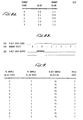
- the grey code counter 64 has a continuous output corresponding to the output as shown in Figure 8A, column 2. As shown in Figure 8A, the grey code output in sequence goes from 00 to 01 to 11 to 10 and then back to 00 in a continuous fashion.
- This grey code output is converted to a binary output also as shown in Figure 8A, column 3.
- the grey code output 00 corresponds to the binary output 11 or 3. It is important to note that upon the transition of the grey code output from 00 to 01, a transition of the binary output is from 11, or 3, to 00 or 0. When this transition occurs, a 9-bit counter 92 is advanced by one count. The 9-bit counter 92 counts continuously from 0 to 511 in binary. When the decimal number 511 is reached, the counter wraps around and continues to count from 0 to 511 again, independently of any ultrasonic echoes that are received. An ultrasonic echo, received on line 86, initiates the sampling process.
- the sample pulse generator 90 generates three sample pulses Pl, P2 and P3 which are present on the leads 102, 104 and 106, respectively.
- the Pl sample pulse occurs 100 ns after an echo is received on lead 86. 25 ns later, sample pulse P2 is generated and 25 ns after that sample pulse P3 is generated.
- a sample pulse is present on lead 102 which causes latch 68 to sample the output of the grey code counter.
- a sample pulse is sent to latch 96 which samples and holds the current counter value of 9-bit counter 92.
- a sample signal is sent via lead 104 to latch 72 which takes another sample of the current grey code count in the grey code counter 64.
- waveform 108 is a representation of the signal from the 40 MHz clock 58 of Figure 6.
- the waveform 110 represents the least significant bit out of grey code counter 64 and the waveform 112 (Gl) represents the other signal (the most significant bit) out of the grey code counter 64.
- Waveform 114 represents the output out of the 9-bit counter 92.
- Waveform 116 represents an ultrasonic echo received on lead 86 into sample pulse generator 90.
- the waveforms 118, 120 and 122 represent the sample pulses P1, P2 and P3 generated in the sample pulse generator (shift register) 90. It should be noted that it is critical that the grey code counter is clocked on the opposite edge of the clock 58 (waveform 108) from the sample pulse generator 90 to avoid metastability in the grey code samples.
- Dotted line 130 of Figure 9 shows that the waveform 110 goes high. This transition causes the 9-bit counter, waveform 114, to start its transition to its next count. Note that the rising edge of waveform 116, the received echo, occurs, in this example, during a transition of the 9-bit counter 92. Since there is a built-in delay of 100 ns between the leading edge of the echo 68 and the leading edge of the sample pulse P1, 118, this delay can be eliminated because it is present for each echo that is sampled.
- the grey code counter 64 is sampled as well as the 9-bit counter 92. As can be seen, the grey code counter has a value of 01 and the 9-bit counter 92 is in a state of transition.
- the output state of the grey code counter is converted to a binary output and for ease of reference we will use the decimal number relating to that binary output.
- column 1 if the first Pl sample results in a binary output of 3 and the following P2 sample results in the same binary output of 3, then the first sample of the 9-bit counter is valid.
- the first Pl sample results in a binary output of 3 and the P2 sample results in a binary output of 0 then there has been one transition of the grey code counter and again the Pl reading of the 9-bit counter is valid.
- the two successive samplings of the grey code counter reveals that a count of the grey code counter has been skipped, such as a Pl reading of 3 and a P2 reading of 1, then the valid state is 0.
- waveform 132 shows a transition of the 9-bit counter which occurs at the 3 to 0 transition of the: grey code counter 64 as shown in the line 134.
- the output of the 9-bit counter 92 is in a state of transition as represented by the x's of the line 136. Therefore, as shown in Figure 9, anytime the valid state of the grey code counter is 0 or 1, the 9-bit counter 92 has a valid sample during the P3 sample, and anytime the valid state is 2 or 3, then the Pl sample of the 9-bit counter is valid.
- the binary output of the grey code counter represents the two least significant bits of the 11-bit counter which corresponds to the 9 bits from the 9-bit counter 92 and the two binary outputs of the grey code counter 64 as converted by binary converter 138 of Figure 6. Since the grey code counter 64 clocks the 9-bit counter on the 3 to 0 transition of the grey code counter, Figure 8B, the first two bits of the grey code converter can be used as part of the 11-bit counter after the grey code counter output has been converted to binary by converter 138.
- a schematic of the gate array 48 is attached hereto as Appendix A. While we believe that the block diagram of Figure 6 and this specification adequately describe and show the gate array, and that no further drawing is necessary, a full schematic is attached so that no question of completeness exists.
- the microprocessor 46 and transducer elements are automatically turned off in order to reduce power consumption and the battery life.
- a small discrete circuit performs this function and also responds to depression of the activation button by activating the electronic elements and the transducer.
Landscapes
- Health & Medical Sciences (AREA)
- Engineering & Computer Science (AREA)
- Physics & Mathematics (AREA)
- Life Sciences & Earth Sciences (AREA)
- Radar, Positioning & Navigation (AREA)
- Remote Sensing (AREA)
- Molecular Biology (AREA)
- General Health & Medical Sciences (AREA)
- Computer Networks & Wireless Communication (AREA)
- Biophysics (AREA)
- Ophthalmology & Optometry (AREA)
- Biomedical Technology (AREA)
- Heart & Thoracic Surgery (AREA)
- Medical Informatics (AREA)
- Acoustics & Sound (AREA)
- Surgery (AREA)
- Animal Behavior & Ethology (AREA)
- General Physics & Mathematics (AREA)
- Public Health (AREA)
- Veterinary Medicine (AREA)
- Nuclear Medicine, Radiotherapy & Molecular Imaging (AREA)
- Pathology (AREA)
- Radiology & Medical Imaging (AREA)
- Ultra Sonic Daignosis Equipment (AREA)
- Measurement Of Unknown Time Intervals (AREA)
- Communication Control (AREA)
- Prostheses (AREA)
- Eye Examination Apparatus (AREA)
Priority Applications (1)
| Application Number | Priority Date | Filing Date | Title |
|---|---|---|---|
| AT86307391T ATE102805T1 (de) | 1985-09-27 | 1986-09-25 | Vorrichtung zur uebernahme von daten bei auftreten asynchroner signale. |
Applications Claiming Priority (2)
| Application Number | Priority Date | Filing Date | Title |
|---|---|---|---|
| US781257 | 1985-09-27 | ||
| US06/781,257 US4817432A (en) | 1985-09-27 | 1985-09-27 | Digital ultrasonic instrument for ophthalmic use |
Publications (3)
| Publication Number | Publication Date |
|---|---|
| EP0222476A2 true EP0222476A2 (de) | 1987-05-20 |
| EP0222476A3 EP0222476A3 (en) | 1988-11-17 |
| EP0222476B1 EP0222476B1 (de) | 1994-03-16 |
Family
ID=25122161
Family Applications (1)
| Application Number | Title | Priority Date | Filing Date |
|---|---|---|---|
| EP86307391A Expired - Lifetime EP0222476B1 (de) | 1985-09-27 | 1986-09-25 | Vorrichtung zur Übernahme von Daten bei Auftreten asynchroner Signale |
Country Status (5)
| Country | Link |
|---|---|
| US (1) | US4817432A (de) |
| EP (1) | EP0222476B1 (de) |
| JP (1) | JPH0696014B2 (de) |
| AT (1) | ATE102805T1 (de) |
| DE (1) | DE3689716T2 (de) |
Cited By (4)
| Publication number | Priority date | Publication date | Assignee | Title |
|---|---|---|---|---|
| EP0219988A3 (en) * | 1985-09-27 | 1988-07-20 | Design Team Partners | Self-contained hand-held ultrasonic instrument for ophthalmic use |
| CN106556309A (zh) * | 2015-09-30 | 2017-04-05 | 捷荣科技集团有限公司 | 一种格雷码带、格雷码带智能卷尺及数据读取方法 |
| CN106556307A (zh) * | 2015-09-30 | 2017-04-05 | 捷荣科技集团有限公司 | 一种可显示面积周长的格雷码带智能卷尺 |
| CN106556304A (zh) * | 2015-09-30 | 2017-04-05 | 捷荣科技集团有限公司 | 一种可扫码的格雷码带智能卷尺及虚拟试衣实现方法 |
Families Citing this family (47)
| Publication number | Priority date | Publication date | Assignee | Title |
|---|---|---|---|---|
| US4747296A (en) | 1985-09-27 | 1988-05-31 | Design Team Partners | Electronic tonometer with baseline nulling system |
| JP2996302B2 (ja) * | 1988-09-22 | 1999-12-27 | 株式会社トプコン | レーザースキャン眼底カメラ |
| FR2650071B1 (fr) * | 1989-07-20 | 1991-09-27 | Asulab Sa | Procede de traitement d'un signal electrique |
| US5308355A (en) * | 1992-11-06 | 1994-05-03 | Alexander Dybbs | Ophthalmic surgical instrument and method |
| US5331962A (en) * | 1993-04-16 | 1994-07-26 | Cornell Research Foundation Inc. | Ultrasound system for corneal biometry |
| USD350907S (en) | 1993-06-10 | 1994-09-27 | Villasenor Richard A | Pachymeter |
| DE19540034B4 (de) * | 1995-10-27 | 2005-04-21 | Gestra Ag | Sonde mit einseitig vorkragendem Kopfgehäuse |
| US6079831A (en) * | 1997-04-24 | 2000-06-27 | Orbtek, Inc. | Device and method for mapping the topography of an eye using elevation measurements in combination with slope measurements |
| US5864383A (en) * | 1997-04-24 | 1999-01-26 | Orbtek, Inc. | Single-curvature placido plate |
| US6225890B1 (en) | 1998-03-20 | 2001-05-01 | Trimble Navigation Limited | Vehicle use control |
| US6115326A (en) * | 1998-10-22 | 2000-09-05 | Integrated Medical Systems, Inc. | Ultrasonic micro-machined selectable transducer array |
| US6113542A (en) * | 1998-12-15 | 2000-09-05 | Hyman; George F. | Diagnostic apparatus and method to provide effective intraocular pressure based on measured thickness of the cornea |
| AU2624701A (en) * | 2000-01-03 | 2001-07-16 | Johns Hopkins University, The | Intraoperative microsurgical ultrasonic device and methods |
| US6887203B2 (en) | 2000-01-06 | 2005-05-03 | Ultralink Ophthalmics Inc. | Ophthalmological ultrasonography scanning apparatus |
| CA2295431A1 (en) | 2000-01-06 | 2001-07-06 | Scott Howard Phillips | Ophthalmic apparatus |
| US6675095B1 (en) | 2001-12-15 | 2004-01-06 | Trimble Navigation, Ltd | On-board apparatus for avoiding restricted air space in non-overriding mode |
| US6876356B2 (en) * | 2002-03-18 | 2005-04-05 | Pegasus Technologies Ltd. | Digitizer pen |
| AU2003284141A1 (en) * | 2002-10-16 | 2004-05-04 | Campbell Science Group, Inc. | Cornea characteristics measuring device |
| US20040193054A1 (en) * | 2003-02-19 | 2004-09-30 | Leblanc Paul D. | Hand-held ophthalmic device |
| US20050030473A1 (en) * | 2003-06-12 | 2005-02-10 | Welch Allyn, Inc. | Apparatus and method for determining intraocular pressure and corneal thickness |
| US20090201172A1 (en) * | 2005-05-16 | 2009-08-13 | Innersea Technology, Inc. | Miniature Physiological Telemeter |
| US7496174B2 (en) | 2006-10-16 | 2009-02-24 | Oraya Therapeutics, Inc. | Portable orthovoltage radiotherapy |
| US7620147B2 (en) | 2006-12-13 | 2009-11-17 | Oraya Therapeutics, Inc. | Orthovoltage radiotherapy |
| US8363783B2 (en) | 2007-06-04 | 2013-01-29 | Oraya Therapeutics, Inc. | Method and device for ocular alignment and coupling of ocular structures |
| US8512236B2 (en) * | 2008-01-11 | 2013-08-20 | Oraya Therapeutics, Inc. | System and method for positioning and stabilizing an eye |
| WO2009085204A2 (en) | 2007-12-23 | 2009-07-09 | Oraya Therapeutics, Inc. | Methods and devices for detecting, controlling, and predicting radiation delivery |
| US7801271B2 (en) * | 2007-12-23 | 2010-09-21 | Oraya Therapeutics, Inc. | Methods and devices for orthovoltage ocular radiotherapy and treatment planning |
| EP2231021A4 (de) * | 2008-01-02 | 2011-06-29 | Arcscan Inc | Bestandteile für einen ultraschallbogenscanner |
| US10531859B2 (en) | 2008-01-02 | 2020-01-14 | Arcscan, Inc. | Components for a precision ultrasonic scanning apparatus for body parts |
| WO2009124271A1 (en) * | 2008-04-03 | 2009-10-08 | Arcscan, Inc. | Procedures for an ultrasonic arc scanning apparatus |
| EP2299912A4 (de) * | 2008-05-29 | 2013-01-23 | Arcscan Inc | Zusammengesetzter scanner-kopf für ein ultraschallgerät |
| US9149254B2 (en) | 2008-12-15 | 2015-10-06 | Arcscan, Inc. | Alignment and imaging of an eye with an ultrasonic scanner |
| CA2784538C (en) | 2008-12-15 | 2016-12-06 | Arc-San, Inc. | Alignment and imaging of an eye with an ultrasonic scanner |
| US8510883B2 (en) * | 2009-10-30 | 2013-08-20 | Arcscan, Inc. | Method of positioning a patient for medical procedures |
| US9597059B2 (en) | 2012-05-17 | 2017-03-21 | Arcscan, Inc. | Correcting for unintended motion for ultrasonic eye scans |
| US9320427B2 (en) | 2012-07-09 | 2016-04-26 | Arcscan, Inc. | Combination optical and ultrasonic imaging of an eye |
| CA2977756A1 (en) | 2014-02-24 | 2015-08-27 | Arcscan, Inc. | Disposable eyepiece system for an ultrasonic eye scanning apparatus |
| CN106557941B (zh) * | 2015-09-30 | 2020-04-07 | 捷荣科技集团有限公司 | 一种基于人体模型的衣服订制方法和系统 |
| US11426611B2 (en) | 2015-10-13 | 2022-08-30 | Arcscan, Inc. | Ultrasound therapeutic and scanning apparatus |
| WO2017066460A1 (en) | 2015-10-13 | 2017-04-20 | Arcscan, Inc | Ultrasonic scanning apparatus |
| JP6727941B2 (ja) * | 2016-06-14 | 2020-07-22 | 株式会社ミツトヨ | 測定器 |
| EP3510738B1 (de) * | 2016-09-08 | 2021-08-25 | Lattice Semiconductor Corporation | Taktrückgewinnung und datenwiederherstellung für programmierbare logische vorrichtungen |
| US11357479B2 (en) | 2018-05-24 | 2022-06-14 | Arcscan, Inc. | Method for measuring behind the iris after locating the scleral spur |
| WO2020263970A1 (en) * | 2019-06-25 | 2020-12-30 | Butterfly Network, Inc. | Methods and apparatuses for processing ultrasound signals |
| US12042329B2 (en) | 2019-12-23 | 2024-07-23 | Arcscan, Inc. | Method and apparatus for controlling an eyelid during imaging |
| WO2021142134A1 (en) | 2020-01-07 | 2021-07-15 | Arcscan, Inc. | Composite ultrasound images |
| DE112021004455T5 (de) | 2020-08-25 | 2023-09-14 | Arcscan, Inc. | Ultraschallaugenscanvorrichtung |
Family Cites Families (7)
| Publication number | Priority date | Publication date | Assignee | Title |
|---|---|---|---|---|
| US4127114A (en) * | 1976-08-30 | 1978-11-28 | Carba S.A. | Apparatus for the automatic measurement of the arterial pressure of a patient |
| US4154114A (en) * | 1977-12-02 | 1979-05-15 | Sonometrics Systems, Inc. | Biometric measuring device |
| EP0013616B1 (de) * | 1979-01-08 | 1984-09-12 | Schlumberger Electronics (U.K.) Limited | Verfahren und Apparat zur Dickenmessung mit Ultraschall |
| NL8002888A (nl) * | 1980-05-19 | 1981-12-16 | Neratoom | Stelsel voor het meten van de wanddikte van een meetobject. |
| US4412248A (en) * | 1982-01-11 | 1983-10-25 | Technicare Corporation | Ultrasonic image storage device and method |
| US4564018A (en) * | 1982-10-28 | 1986-01-14 | Storz Instrument Company | Ultrasonic system for obtaining ocular measurements |
| US4508121A (en) * | 1983-08-08 | 1985-04-02 | Medsys, Inc. | Apparatus for measurement of corneal thickness |
-
1985
- 1985-09-27 US US06/781,257 patent/US4817432A/en not_active Expired - Lifetime
-
1986
- 1986-09-25 EP EP86307391A patent/EP0222476B1/de not_active Expired - Lifetime
- 1986-09-25 AT AT86307391T patent/ATE102805T1/de not_active IP Right Cessation
- 1986-09-25 DE DE3689716T patent/DE3689716T2/de not_active Expired - Fee Related
- 1986-09-26 JP JP61227910A patent/JPH0696014B2/ja not_active Expired - Lifetime
Non-Patent Citations (1)
| Title |
|---|
| IBM TECHNICAL DISCLOSURE BULLETIN, vol. 16, no. 7, December 1973 (1973-12-01) |
Cited By (7)
| Publication number | Priority date | Publication date | Assignee | Title |
|---|---|---|---|---|
| EP0219988A3 (en) * | 1985-09-27 | 1988-07-20 | Design Team Partners | Self-contained hand-held ultrasonic instrument for ophthalmic use |
| CN106556309A (zh) * | 2015-09-30 | 2017-04-05 | 捷荣科技集团有限公司 | 一种格雷码带、格雷码带智能卷尺及数据读取方法 |
| CN106556307A (zh) * | 2015-09-30 | 2017-04-05 | 捷荣科技集团有限公司 | 一种可显示面积周长的格雷码带智能卷尺 |
| CN106556304A (zh) * | 2015-09-30 | 2017-04-05 | 捷荣科技集团有限公司 | 一种可扫码的格雷码带智能卷尺及虚拟试衣实现方法 |
| CN106556309B (zh) * | 2015-09-30 | 2020-02-07 | 捷荣科技集团有限公司 | 一种格雷码带、格雷码带智能卷尺及数据读取方法 |
| CN106556304B (zh) * | 2015-09-30 | 2020-02-18 | 捷荣科技集团有限公司 | 一种可扫码的格雷码带智能卷尺及虚拟试衣实现方法 |
| CN106556307B (zh) * | 2015-09-30 | 2020-02-18 | 捷荣科技集团有限公司 | 一种可显示面积周长的格雷码带智能卷尺 |
Also Published As
| Publication number | Publication date |
|---|---|
| EP0222476B1 (de) | 1994-03-16 |
| ATE102805T1 (de) | 1994-04-15 |
| EP0222476A3 (en) | 1988-11-17 |
| DE3689716T2 (de) | 1994-07-07 |
| JPH0696014B2 (ja) | 1994-11-30 |
| DE3689716D1 (de) | 1994-04-21 |
| US4817432A (en) | 1989-04-04 |
| JPS62142538A (ja) | 1987-06-25 |
Similar Documents
| Publication | Publication Date | Title |
|---|---|---|
| US4817432A (en) | Digital ultrasonic instrument for ophthalmic use | |
| EP0219988B1 (de) | Unabhängiges, tragbares Ultraschall-Instrument zur Anwendung in der Augenheilkunde | |
| US6030343A (en) | Single beam tone burst ultrasonic non contact tonometer and method of measuring intraocular pressure | |
| EP0217642B1 (de) | Tragbares unabhängiges elektronisches Ionometer | |
| WO1989012424A1 (en) | Hand held spring-loaded ultrasonic probe | |
| WO1999058080A1 (en) | Surface acoustic wave periodontal probe and method of detecting periodontal disease | |
| CN101785683A (zh) | 超声波眼科测量装置及方法 | |
| COLEMAN et al. | A new system for visual axis measurements in the human eye using ultrasound | |
| CN1257698C (zh) | 测量病人眼睛轴向距离的眼睛测量系统和方法 | |
| US4377727A (en) | Stethoscope having means for measuring pulse frequency | |
| CN203763050U (zh) | 瞳孔仪 | |
| US4993427A (en) | Heart contraction monitor | |
| JPH06213646A (ja) | 超音波測定装置 | |
| EP0620719A1 (de) | Tonometer | |
| US20060241437A1 (en) | Pachymeter | |
| US20040193054A1 (en) | Hand-held ophthalmic device | |
| EP1701652B1 (de) | Vorrichtung zur messung des augeninnendrucks | |
| US7824036B2 (en) | Ophthalmic ultrasonic measurement apparatus, and an ophthalmic measurement method | |
| US20220378291A1 (en) | Ultrasound Intraocular Pressure Sensor in Sclera or in Cornea | |
| CA2147149A1 (en) | A device for examining the eye, in particular the human eye | |
| US4934370A (en) | Pinhole focused optics for locating visual axis of the eye for ultrasonic interior measurement | |
| FI131113B1 (en) | Device and method of measuring properties of target | |
| CN111329443A (zh) | 一种睫状肌疲劳检测方法及装置、电子设备 | |
| Thijssen | Echo-ophthalmology: physical principles and diagnostic value | |
| EP0070306A1 (de) | Apparat und verfahren zur durchführung einer hornhautchirurgie |
Legal Events
| Date | Code | Title | Description |
|---|---|---|---|
| PUAI | Public reference made under article 153(3) epc to a published international application that has entered the european phase |
Free format text: ORIGINAL CODE: 0009012 |
|
| AK | Designated contracting states |
Kind code of ref document: A2 Designated state(s): AT BE CH DE FR GB IT LI LU NL SE |
|
| PUAL | Search report despatched |
Free format text: ORIGINAL CODE: 0009013 |
|
| AK | Designated contracting states |
Kind code of ref document: A3 Designated state(s): AT BE CH DE FR GB IT LI LU NL SE |
|
| 17P | Request for examination filed |
Effective date: 19890509 |
|
| 17Q | First examination report despatched |
Effective date: 19910419 |
|
| RAP1 | Party data changed (applicant data changed or rights of an application transferred) |
Owner name: BIO-RAD LABORATORIES, INC. |
|
| RAP1 | Party data changed (applicant data changed or rights of an application transferred) |
Owner name: MENTOR O & O, INC |
|
| GRAA | (expected) grant |
Free format text: ORIGINAL CODE: 0009210 |
|
| AK | Designated contracting states |
Kind code of ref document: B1 Designated state(s): AT BE CH DE FR GB IT LI LU NL SE |
|
| PG25 | Lapsed in a contracting state [announced via postgrant information from national office to epo] |
Ref country code: SE Free format text: THE PATENT HAS BEEN ANNULLED BY A DECISION OF A NATIONAL AUTHORITY Effective date: 19940316 Ref country code: NL Effective date: 19940316 Ref country code: LI Effective date: 19940316 Ref country code: CH Effective date: 19940316 Ref country code: BE Effective date: 19940316 Ref country code: AT Effective date: 19940316 |
|
| REF | Corresponds to: |
Ref document number: 102805 Country of ref document: AT Date of ref document: 19940415 Kind code of ref document: T |
|
| REF | Corresponds to: |
Ref document number: 3689716 Country of ref document: DE Date of ref document: 19940421 |
|
| ITF | It: translation for a ep patent filed | ||
| ET | Fr: translation filed | ||
| REG | Reference to a national code |
Ref country code: CH Ref legal event code: PL |
|
| NLV1 | Nl: lapsed or annulled due to failure to fulfill the requirements of art. 29p and 29m of the patents act | ||
| PG25 | Lapsed in a contracting state [announced via postgrant information from national office to epo] |
Ref country code: LU Free format text: LAPSE BECAUSE OF NON-PAYMENT OF DUE FEES Effective date: 19940930 |
|
| PLBE | No opposition filed within time limit |
Free format text: ORIGINAL CODE: 0009261 |
|
| STAA | Information on the status of an ep patent application or granted ep patent |
Free format text: STATUS: NO OPPOSITION FILED WITHIN TIME LIMIT |
|
| 26N | No opposition filed | ||
| PGFP | Annual fee paid to national office [announced via postgrant information from national office to epo] |
Ref country code: GB Payment date: 19960808 Year of fee payment: 11 |
|
| PGFP | Annual fee paid to national office [announced via postgrant information from national office to epo] |
Ref country code: FR Payment date: 19960910 Year of fee payment: 11 |
|
| REG | Reference to a national code |
Ref country code: FR Ref legal event code: CD |
|
| PG25 | Lapsed in a contracting state [announced via postgrant information from national office to epo] |
Ref country code: GB Free format text: LAPSE BECAUSE OF NON-PAYMENT OF DUE FEES Effective date: 19970925 |
|
| PG25 | Lapsed in a contracting state [announced via postgrant information from national office to epo] |
Ref country code: FR Free format text: THE PATENT HAS BEEN ANNULLED BY A DECISION OF A NATIONAL AUTHORITY Effective date: 19970930 |
|
| GBPC | Gb: european patent ceased through non-payment of renewal fee |
Effective date: 19970925 |
|
| REG | Reference to a national code |
Ref country code: FR Ref legal event code: ST |
|
| PGFP | Annual fee paid to national office [announced via postgrant information from national office to epo] |
Ref country code: DE Payment date: 19990927 Year of fee payment: 14 |
|
| PG25 | Lapsed in a contracting state [announced via postgrant information from national office to epo] |
Ref country code: DE Free format text: LAPSE BECAUSE OF NON-PAYMENT OF DUE FEES Effective date: 20010601 |
|
| PG25 | Lapsed in a contracting state [announced via postgrant information from national office to epo] |
Ref country code: IT Free format text: LAPSE BECAUSE OF NON-PAYMENT OF DUE FEES;WARNING: LAPSES OF ITALIAN PATENTS WITH EFFECTIVE DATE BEFORE 2007 MAY HAVE OCCURRED AT ANY TIME BEFORE 2007. THE CORRECT EFFECTIVE DATE MAY BE DIFFERENT FROM THE ONE RECORDED. Effective date: 20050925 |