EP0221775A1 - Testable voted logic power circuit and method of testing the same - Google Patents
Testable voted logic power circuit and method of testing the same Download PDFInfo
- Publication number
- EP0221775A1 EP0221775A1 EP86308455A EP86308455A EP0221775A1 EP 0221775 A1 EP0221775 A1 EP 0221775A1 EP 86308455 A EP86308455 A EP 86308455A EP 86308455 A EP86308455 A EP 86308455A EP 0221775 A1 EP0221775 A1 EP 0221775A1
- Authority
- EP
- European Patent Office
- Prior art keywords
- switches
- load
- current
- actuation
- actuated
- Prior art date
- Legal status (The legal status is an assumption and is not a legal conclusion. Google has not performed a legal analysis and makes no representation as to the accuracy of the status listed.)
- Granted
Links
Images


Classifications
-
- G—PHYSICS
- G21—NUCLEAR PHYSICS; NUCLEAR ENGINEERING
- G21D—NUCLEAR POWER PLANT
- G21D3/00—Control of nuclear power plant
- G21D3/04—Safety arrangements
-
- G—PHYSICS
- G05—CONTROLLING; REGULATING
- G05B—CONTROL OR REGULATING SYSTEMS IN GENERAL; FUNCTIONAL ELEMENTS OF SUCH SYSTEMS; MONITORING OR TESTING ARRANGEMENTS FOR SUCH SYSTEMS OR ELEMENTS
- G05B9/00—Safety arrangements
- G05B9/02—Safety arrangements electric
- G05B9/03—Safety arrangements electric with multiple-channel loop, i.e. redundant control systems
-
- Y—GENERAL TAGGING OF NEW TECHNOLOGICAL DEVELOPMENTS; GENERAL TAGGING OF CROSS-SECTIONAL TECHNOLOGIES SPANNING OVER SEVERAL SECTIONS OF THE IPC; TECHNICAL SUBJECTS COVERED BY FORMER USPC CROSS-REFERENCE ART COLLECTIONS [XRACs] AND DIGESTS
- Y02—TECHNOLOGIES OR APPLICATIONS FOR MITIGATION OR ADAPTATION AGAINST CLIMATE CHANGE
- Y02E—REDUCTION OF GREENHOUSE GAS [GHG] EMISSIONS, RELATED TO ENERGY GENERATION, TRANSMISSION OR DISTRIBUTION
- Y02E30/00—Energy generation of nuclear origin
Definitions
- the invention is directed to protection systems used to provide reliable automatic responses to abnormal conditions in complex processes, such as in nuclear power plants, and to apparatus and a method for testing such protection systems. More specifically, the invention is directed to voted logic power circuits for such a protection system which can be used with normally energized or normally deenergized protection devices and to a tester which tests each switching component of the power circuit while maintaining the protection function.
- Protection systems for complex processes monitor selected process parameters, such as temperatures, pressures and flows, and the status of various components such as whether a valve is open or closed or whether a pump is on or off, and provide automatic responses to measured values of the parameters and to detected status states of the components which require positive intervention to prevent, or to alleviate the effects of, abnormal process conditions.
- High reliability is an essential requirement for such a system.
- a nuclear power plant is one example of a complex process in which such a protection system is employed.
- the protection system in a nuclear power plant performs a plurality of functions. It can shutdown, or trip, the reactor if conditions warrant, or it can perform a number of engineered safeguard functions, such as opening or closing valves and turning on or off pumps or other components.
- the trip function involves deenergizing electromechanical jacks which normally hold control rods in a position withdrawn from the reactor core so that the rods reenter the core and cause it to go subcritical.
- the engineered safeguard functions may involve either deenergizing a load device which is normally energized or energizing a device which is normally deenergized.
- each sensor is compared with a setpoint value to generate a digital signal which is referred to as a partial actuation signal since an indication from more than one sensor is required to actuate the safety component.
- the four partial actuation signals for each parameter or status condition are all fed to each of two identical, electrically isolated logic trains. Typically, this is accomplished by applying each partial actuation signal to the coil of a relay having one set of contacts in each logic train. Each logic train independently votes the partial actuation signals, such as two out of four, and generates an actuation signal.
- the two independently generated actuation signals are then applied to a power interface circuit which requires the presence of both actuation signals to actuate the load device, either a normally energized or normally deenergized component, to initiate the engineered safeguard function.
- a power interface circuit which requires the presence of both actuation signals to actuate the load device, either a normally energized or normally deenergized component, to initiate the engineered safeguard function.
- Such a two out of two voting power interface can be disabled by a single failure in one of the two channels.
- the prior art systems for testing power interfaces utilize feedback signals which indicate the presence or absence of current in the various circuit legs or they generate analog or digital representations of current magnitude.
- One problem with test schemes which rely on reading current magnitude is that the current varies as a function of power supply voltage. In the case of a nominal 120 volt DC system, a voltage swing of 50 volts may occur between a low battery condition (approximately 100 VDC) and a full battery or charging condition (approximately 150 VDC).
- the sensor channels are tested individually one at a time by substituting test signals for the sensor signals.
- both logic drains are tested simultaneously which also tests the power interface.
- the logic trains are tested one at a time.
- the switches are individually switched out of the power interface network and tested by a low impedance test circuit.
- the topography of the power interface circuit is changed to effect the test.
- a primary object. of the present invention is to provide a protection system which is not disabled by a single failure even during testing.
- the invention also provides a testable voted logic protection system in which the same circuit topography can be used for both normally energized and normally deenergized switches, without interrupting the protection function and without change in circuit topology.
- the preferred system is realized by an n out of m voted logic power interface circuit in which m sets of switches are arranged in a plurality of groups of switches with the groups of switches connected in parallel with each other and in series with a voltage source and a load.
- Each group of switches include a different selection of n switches connected in series, each from a different one of the m sets of switches.
- the plurality of groups of switches include all possible combinations of m sets taken n at a time such that with at least n out of the m sets of switches actuated the load device is actuated.
- Each of the switches is shunted by a resistor to provide a leakage path through each group of switches.
- the impedance of the shunt resistors is several magnitudes greater than that of a closed switch so that the leakage current is insufficient to energize the load.
- Detectors associated with each group of switches and responsive to changes in impedance in the group, generate output signals indicative of the state of the switches.
- the detectors Preferably, the detectors generate digital signals having a first value when none of the switches are actuated and a second value when at least one switch in the group is actuated.
- actuated means that the referenced device is in its operated condition.
- a normally closed switch is open when actuated, and a normally open switch is closed.
- a normally deenergized load is energized in its actuated state and a normally energized load is deenergized.
- each group of switches is incorporated into a resistance measuring bridge circuit in which the voltage drop across the resistor shunted switches is compared with a reference voltage. Both of these voltages are proportional to the supply voltage so that reliable indications of switch actuation are generated despite even large fluctuations in supply voltage.
- the voltage drop across the group of resistor shunted switches forming one leg of the bridge is applied to one input of a comparator and the reference voltage generated by the other side of the bridge is applied to the other comparator input.
- the three reference resistors in the bridge circuit are selected such that the comparator has two discrete outputs; one when none of the switches are actuated and another when at least one of them is actuated.
- the reference resistors are selected such that the reference voltage developed by the bridge and applied to the comparator is about halfway between the voltage drop across the group of resistor shunted switches when no switches are actuated, and that when at least one switch is actuated, for all supply voltages.
- the invention is particularly adapted for use in a protection system for a nuclear power plant where redundant sets of sensors monitor selected reactor parameters and multiple logic trains independently generate a voted logic actuation signal for each set of switches from redundant signals generated by the sensors.
- a test unit selectively generates test actuation signals and monitors the detectors for preselected patterns of digital signals. By generating fewer actuation signals than are required to actuate the load, the tests can be performed while the protection system remains on line, for both normally energized and normally deenergized loads. Hence, the protection function is not interrupted during test and no changes in circuit topology are required.
- the invention in its broad form resides in a process control arrangement a testable protection system using a two out of three voted power circuit, comprising: a load; a voltage source connectable to the load, characterized by three pairs of switches connected in three groups of two switches each with the two switches in each group associated with a different pair of switches and being connected in parallel, and with the three groups of switches being connected in series with each other, and with the load across the voltage source; means for generating three independent actuating signals; means for applying a different one of said actuating signals independently to one of said pairs of switches to actuate the same, and thereby actuate the load device only if at least two out of the three actuating signals are generated; a resistor shunting each group of switches to provide a leakage path between the voltage source and the load device; and a current detector for measuring the current drawn from the voltage source, the impedance of said resistors having impedances several magnitudes larger than the impedance of a closed switch such that the current through said leakage path
- a power circuit for actuating a load in response to any two out of three actuation signals includes three pairs of switches connected in three groups of two switches each, with the two switches in each group each being associated with a different pair of switches and being connected in parallel.
- the three groups of switches are connected in series with each other and with the load across a voltage source.
- One of the actuation signals actuates each of the pairs of switches such that in the presence of any two actuation signals the load is actuated.
- the same circuit topography is used whether the load is a normally energized or normally deenergized device.
- the switches are normally open and are closed when actuated. Conversely, normally closed switches are used when the load is normally energized.
- the load is actuated by disconnecting it from the voltage source and the normally deenergized load is actuated by connecting it to the voltage source.
- the power circuit is tested by shunting each group of switches with a resistor such that together the resistors form a leakage path through the network of switches.
- the value of the resistors is selected to be several magnitudes larger than that of a closed switch and such that the leakage current is insufficient to energize the load but sufficient that it can be detected by a leakage current detector measuring the current flowing to the load.
- the power circuit is tested by generating one actuation signal at a time to actuate the associated pair of switches, one in each of two different groups of switches. The increase in current effected by the closing of normally open switches, or the decrease in current resulting from the opening of normally closed switches, is detected by the current detector.
- Generation of the actuation signals and monitoring of the detected current can be placed under the control of an automatic tester.
- failure of any of the switches either during an actuation or a quiescent period can be detected at the time it occurs rather than waiting for a conventional system test.
- the same basic configuration and method can be used for testing any power circuit in which the load is to be actuated by n out of m actuation signals.
- m sets of switches are arranged in a plurality of groups of switches connected in series with the load across the voltage source.
- Each group includes n switches connected in parallel, with each of the n switches in each group associated with a different one of said sets of switches.
- the number of groups of switches required is a function of the number of possible different combinations of switches taken from m sets n at a time.
- the load may be either normally energized or normally deenergized by utilizing normally closed or normally open switches, respectively.
- Each of the plurality of serially connected groups of switches is shunted by a resistor having an impedance which is several times that of a closed switch to form through the switching network a leakage path in which the current is insufficient to energize the load but large enough to be detected by the current detector.
- the numbers m and n become larger, the relative effect of the failure of a single switch on the current becomes smaller and requires more sensitive equipment to detect.
- the two out of three voted power circuit of this invention When applied to a protection system for a nuclear reactor in which redundant sensors for selected parameters generate partial actuation signals which are all applied to three logic trains which in turn, each generate an actuation signal based upon a selected voting logic, the two out of three voted power circuit of this invention, with the testing feature, provides a system which can be monitored continuously for switch failure, can be tested without changing circuit topography, is not subject to single failure even during testing and can be used with either normally energized or normally deenergized loads.
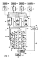
- the exemplary system 1 employs four redundant sets of sensors 3 to monitor selected plant parameters such as pressure, temperature, flow, radiation level, et cetera, and/or the status of various components, such as whether a valve is open or closed or whether a pump is running or not. Where such a system is used for a particular safeguard function, the sensors 3 may monitor only one or a plurality of plant parameters or conditions.
- the signals generated by each set of sensors 3 are applied to separate channel sets 5, numbered 1 through 4 in Figure 1, where the detected values of the sensor signals are analyzed for an indication of an abnormal condition by comparing them with selected setpoint values.
- the values of measured parameters are used to calculate other parameters which are then compared with limiting values for an indication of an abnormal condition as is well-known in the field of control system engineering.
- Each channel set generates a digital output signal which indicates whether or not the sensors in that channel set are sensing conditions which warrant actuation of the associated safeguard function. Since confirmation by more than one channel set is required to initiate the safeguard function, the digital signals are referred to as "partial actuation signals”.
- the partial actuation signals from each of the channel sets 5 are each applied to three independent logic trains 7 labeled A, B and C in Figure 1.
- they are electrically isolated from one another such as by applying each of them to the coil of a separate relay in each logic train as is now common practice.
- the coil to contact separation of these relays provides the electrical isolation between the actuation signals and between the logic trains. Isolation could also be provided for instance, by optical isolators where solid state switches are used in place of relays.
- the logic trains 7 independently vote the partial trip signals received from the four channel sets 5 and generate an actuation signal on their associated output lines 9 when the prescribed number of partial trip signals is detected.
- two out of four voting logic is employed by these logic trains. That is, two out of the four channel sets must be generating a partial actuation signal in order for the logic train to generate an actuation signal.
- Such a scheme allows for failures which preclude the generation of a partial actuation signal by two of the channel sets, while reducing the likelihood of a spurious trip which could occur if only one partial trip signal was required to generate an actuation signal.
- all four channel sets would generate partial actuation signals upon the occurrence of the abnormal condition, and all three logic trains 7 would generate an actuation signal.
- voting strategies other than two of four could be employed by the logic trains 7.
- the actuation signals on the leads 9 are utilized to control the energization of a load device 11 by a voltage source V through a power interface identified generally in Figure 1 by the reference character 13.
- the load device may be any type of electrically operated device which effects an automatic response to the detection of the associated abnormal condition.
- a device could be for example, a pump, an electrically controlled valve, a heater, a circuit breaker or any motor driven device.
- the load device would be a normally deenergized device, but as will be seen, the invention can also be used with normally energized load devices also.
- the power interface 13 includes a network of switches connected in series with the load device 11 across the voltage source V.
- the switches are the normally open contacts 15 of relays 17 individually identified as Al, A2, Bl, B2, Cl and C2.
- the coils 19 of the two relays 17 are connected to the output line 9 from each logic train 7.
- the contacts of these coils are connected in three groups 21 of two contacts each with the two contacts in each group connected in parallel and the groups connected in series.
- the two contacts in each group are associated with relays energized by different logic trains.
- the first group includes the make contacts of relays B1 and A2; the second, contacts of relays Al and Cl; and the third contacts of relays B2 and C2.
- Another advantage of the invention is that the same basic arrangement of the power interface can be used for normally energized as well as normally deenergized load devices.
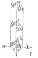
- the normally closed break contacts 15' of two relays 17', the coils 19' of which are connected to each logic train actuation line 9, are arranged in three series connected groups of two contacts each in parallel.
- a path through the switching network 13' remains complete unless actuation signals are generated on two out of three of the lines 9.
- the load device is actuated by interrupting the power to the load device 11'. Again, spurious actuations are reduced by requiring confirmation of two out of three of the logic trains and the system is not disabled by a single failure.
- the present invention includes a unique arrangement for testing protection systems such as those disclosed in Figures 1 and 2.
- each group 21 or 21' of relay contacts is shunted by a resistor 23 which, because the three groups of relay contacts are connected in series, form a leakage path through the network 13 or 13'.
- a current detector 25 measures the current drawn from the voltage source by the load 11 or 11' and the switching network 13 or 13' including the leakage path through the resistors 23. The current detected by the current detector is applied to a tester 27 which analyzes the detected current based upon test inputs to determine the condition of the tested components.
- the resistance of the resistors 23, is sufficiently large that the leakage current through them is insufficient to energize the load device 11, 11' yet is large enough to be detected by the current detector 25.
- the value of these resistors 23 is also several magnitudes larger than that of the contact resistance of the contacts 15, 15' as represented by the resistances 29, 29' shown in series with the contacts, such that the current through a closed set of contacts 15, 15' is measurably larger than that through the associated shunt resistor 23.
- the power interface can be automatically tested without actuating the load device, whether it is normally energized or deenergized, and without changing the circuit topography, while continuously maintaining the protection function.
- the tester 27 sends signals to one of the logic trains 7 at a time disconnecting the inputs from the channel sets 5 and substituting test signals.
- Various combinations of these test signals can be generated by the tester to test the logic train.
- Certain combinations of the test signals will generate an actuation signal on the associated actuation line 9 thereby energizing the associated relays. For instance, during testing of logic train A, relays A1 and A2 will be energized.
- the other logic trains 7 are tested sequentially in a similar manner.
- the voting logic of the power interface 13 is transformed from two out of three logic to one out of two. That is, with one logic train generating an actuation signal induced by the tester, only one of the other logic trains need detect an abnormal condition for the load device to be actuated. For instance, with channel A under test, an actuation signal from either channel B or C will complete a low resistance path through the power interface to energize the load device 11. This transformation is achieved without any change in circuit topography. It also assures that the power interface is not disabled by a single failure in the remaining active channels during testing as in the prior art.
- the following table sets forth the currents that will be detected under the specified conditions where the value of the resistors 23 is 10K ohms, the resistance 29, 29' of the contacts 15, 15' is 1 ohm, the resistance of the load device 11, 11' is 500 ohms and the voltage V is 125 volts d-c.
- the invention provides the capability of monitoring the performance of each logic train 7 and each switch 17 in the power interface network 13, 13'. It not only provides the capability of specifically testing each of the components but can also be used to provide on-line continuous monitoring of these components.
- the arrangement for testing the power interface is not confined to testing a two out of three voting logic network.
- it can also be used to test and monitor the prior art a two out of two voting logic power interface for normally deenergized and normally energized loads as shown in Figures 3 and 4, respectively.
- it can be used for any power interface network having m sets of switches where the switches are arranged in a plurality of groups of switches connected in series with the load across the voltage source.
- Each group of switches comprises a different selection of n switches each from a different set of switches all connected in parallel such that with at least n sets of switches actuated, the load is actuated.
- a resistor such a resistor 23, shunts each of the m groups of switches to provide the leakage path through the network.
- the exemplary system 1 employs four redundant sets of sensors 3 to monitor selected plant parameters such as pressure, temperature, flow, radiation level, et cetera, and/or the status of various components, such as whether a valve is open or closed or whether a pump is running or not. Where such a system is used for a particular safeguard function, the sensors 3 may monitor only one or a plurality of plant parameters or conditions.
- each set of sensors 3 are applied to separate channel sets 5, numbered 1 through 4 in Figure 4, where the detected values of the sensor signals are analyzed for an indication of an abnormal condition by comparing them with selected setpoint values. In some instances, the values of measured parameters are used to calculate other parameters which are then compared with limiting values for an indication of an abnormal condition as is well-known in the field of control system engineering.
- Each channel set generates a digital output signal which indicates whether or not the sensors in that channel set are sensing conditions which warrant actuation of the associated safeguard function. Since confirmation by more than one channel set is required to initiate the safeguard function, the digital signals are referred to as "partial actuation signals".
- the partial actuation signals from each of the channel sets 5 are each applied to three independent logic trains 7 labeled A, B and C in Figure 5.
- they are electrically isolated from one another such as by applying each of them to the coil of a separate relay in each logic train as is now common practice.
- the coil to contact separation of these relays provides the electrical isolation between the actuation signals and between the logic trains. Isolation could also be provided for instance, by optical isolators where solid state switches are used in place of relays.
- the logic trains 7 which may preferably comprise microcomputer systems, independently vote the partial trip signals received from the four channel sets 5 and generate an actuation signal a, b or c on their associated output lines 9 when the prescribed number of partial trip signals is detected.
- two out of four voting logic is employed by these logic trains. That is, two out of the four channel sets must be generating a partial actuation signal in order for the logic train to generate an actuation signal.
- Such a scheme allows for failures which preclude the generation of a partial actuation signal by two of the channel sets, while reducing the likelihood of a spurious trip which could occur if only one partial trip signal was required to generate an actuation signal.
- all four channel sets would generate partial actuation signals upon the occurrence of the abnormal condition, and all three logic trains 7 would generate an actuation signal.
- voting strategies other than two out of four could be employed by the logic trains 7.
- the actuation signals on the leads 9 are utilized to control the energization of a load device 11 by a voltage source V through a power interface identified generally in Figure 1 by the reference character 13.
- the load device 11 may be any type of electrically operated device which effects an automatic response to the detection of the associated abnormal condition. Such a device could be for example, a pump, an electrically controlled valve, a heater, a circuit breaker or any motor driven device.
- the load device would be a normally deenergized device, but as will be seen, the invention can also be used with normally energized load devices also.
- the power interface 13 includes a network of switches connected in series with the load device 11 across the voltage source V.
- the switches are the normally open contacts 15 of relays A, (A), B, (B), C and (C).
- the coils 17 of two relays are connected to the output line 9 from each logic train 7.
- the contacts of these coils are connected in three groups 19 of two contacts each with the two contacts in each group connected in series and the groups connected in parallel.
- the two contacts in each group are associated with relays energized by different logic trains.
- the first group includes the make contacts of relays A and B; the second, contacts of relays (A) and (C); and the third, contacts of relays (B) and C.
- each of the switches 15 is shunted by a resistor R1, and a current monitor 21 is connected in each branch of the switching network.
- a microprocessor based tester 23 generates test signals which are applied through lines 25 to the logic trains to cause the latter to selectively generate the actuation signals a, b and c.
- the current registered by each of the current monitors 21 is feedback to the tester 23 over lines 27.
- the resistors R1 provide a leakage path through each group 19 of switches in the power interface 13, however, they are selected to have an impedance which is several magnitudes greater than that of a closed switch so that the total leakage current is insufficient to energize the load 11.
- a suitable value for the resistors R1 is 30,000 ohms. Under these conditions, if both switches in one leg of the switching network are open, the corresponding current monitor 21 will register a current of about 2 milliamps and the load will not be energized. This is defined as the "OFF" state.
- the current will be about 4 milliamps and this is defined as the "ON" state for the interface employing make contacts although the load will still be deenergized at this current level.
- the current is about 1 amp and the load is energized. This is also defined as an "ON" state.
- the operability of each device can be checked by forcing the inputs using the tester 23 and monitoring the "OFF"/"ON" status of each branch in the switching network.
- the tester 23 generates a pattern of test signals and compares the results reported back by the current monitors 21 with a stored expected pattern of responses. Any deviation from the expected responses is identified as an indication of a malfunction.
- Table I below illustrates the test sequence for the power interface circuit of Figure 1 for the normally deenergized load shown:
- the circuit of Figure 5 can also be used with normally energized loads in which case the switches 15 would all comprise break contacts of the associated relays, and the load device 11 would be actuated by interruption of the energizing current in response to generation of two out of three of the actuation signals a, b and c.
- the "OFF" state is defined as a condition in which at least one of the break contacts in a group is open.
- the power interface circuit 13 utilizing break contacts would be tested in the same manner-as discussed above through generation of a pattern of actuation signals under the direction of the tester 23. Table II below illustrates the test sequence for the circuit of Figure 1 with a normally energized load:
- the groups 19 of switches 15 are incorporated into a series of parallel resistance bridges as shown in Figure 6.
- the resistor shunted switches 15 of each group form one leg of a wheatstone bridge circuit and are connected in series with a reference resistor R3, forming a second leg, at a first node 29.
- Reference resistors R5 and R6 forming the remaining two legs of the bridge circuit generate a reference voltage, Vref, at a second node 31.
- the legs formed by resistors R5 and R6 are shared by each of the three bridge circuits so that a common Vref is generated.
- Each bridge is spanned between nodes 29 and 31 by a comparator 33 which compares the voltage drop generated by the associated group of resistor shunted switches 15 with Vref.
- the comparator 33 generates a digital output which assumes an "ON" state when the voltage at the first node 29 exceeds Vref indicating that at least one of the normally open resistor shunted switches is closed, and assumes an "OFF" state, indicating that both switches are open, when Vref exceeds the voltage at node 29.
- Reference to Tables I and II will confirm that each switching state that the interface is capable of assuming can be verified by interrogating the digital status of each comparator 33 in light of the inputs imposed by tester 23.
- Vref the comparator trip point
- a further advantage of the invention is that the feedback signals on lines 27 consist of 3 single bit signals which directly specify the switching state of the interface rather than current magnitudes from which the switching state is deduced.
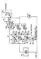
- Figure 7 illustrates a practical circuit for implementing the invention for d-c power interfaces utilizing solid state switching devices.
- power FETs 35 are utilized as the switching devices between the load 11 and power supply 12.
- the FETs are switched by square wave actuation signals a, b and c generated by the logic trains 7 through conventional drive circuits 37 which convert the a-c logic signal to a d-c control signal.
- the transformers 39 in the drive circuit provide isolation between the logic trains 7 and the power interface 13.
- the output circuit 41 for each group of switches includes the comparator 33 which compares Vref generated by the resistors R5 and R6 with the voltage at node 29.
- the voltage at node 29 is applied to the positive input of the comparator 33 through an input resistor R4 with the switching noise filtered out by a capacitor Cl.
- An LED 43 is energized by the digital output of the comparator 33 when the voltage Va exceeds Vref. Radiation from the LED 43 turns ON a phototransistor 45 to provide an isolated output for the comparator.
- a diode 47 prevents reverse biasing of LED 43.
- Similar isolated, single bit digital output circuits 41 are provided for each of the other groups 19 of switches.
- Each of the FETs 35 is turned ON when a square wave signal is applied to the drive circuit 37.
- no signal is applied to the drive circuits under normal conditions so that the FETs are OFF.
- the voltage, Va, at node 29 for each of the groups of switches is lower than Vref so that the output of the comparator 33 is low, the LED is OFF and therefore the phototransistor does not conduct.
- the digital output FEEDBACK signal which is returned to the tester over line 27 is high.
- the tester induces a logic train 7 to generate a square wave actuation signal
- one of the FETs in each of two of the groups 19 of switches is turned ON. This raises the voltage at node 29 above Vref for those groups of switches, causing the comparators to turn ON the associated LEDs, which in turn, turn on the phototransistors to cause their FEEDBACK signals to go low.
- relays as the switches
- other switching devices could also be used, such as triacs, SCRs, or power MOSFETs.
- the resistance 29, 29' represents the dynamic resistance of the device.
- These solid state switches may be isolated to maintain separation of the channels by for instance, opto-isolators or other suitable protection grade isolation devices.
Abstract
Description
- The invention is directed to protection systems used to provide reliable automatic responses to abnormal conditions in complex processes, such as in nuclear power plants, and to apparatus and a method for testing such protection systems. More specifically, the invention is directed to voted logic power circuits for such a protection system which can be used with normally energized or normally deenergized protection devices and to a tester which tests each switching component of the power circuit while maintaining the protection function.
- Protection systems for complex processes monitor selected process parameters, such as temperatures, pressures and flows, and the status of various components such as whether a valve is open or closed or whether a pump is on or off, and provide automatic responses to measured values of the parameters and to detected status states of the components which require positive intervention to prevent, or to alleviate the effects of, abnormal process conditions. High reliability is an essential requirement for such a system. In order to enhance reliability, it is common practice to provide redundant sensors for each selected parameter and component status. It is also common practice to vote the responses of the redundant sensors, that is to require that a plurality, but not necessarily all, of the sensors, detect the abnormal condition before action is initiated in order to reduce the probability of a spurious actuation.
- A nuclear power plant is one example of a complex process in which such a protection system is employed. The protection system in a nuclear power plant performs a plurality of functions. It can shutdown, or trip, the reactor if conditions warrant, or it can perform a number of engineered safeguard functions, such as opening or closing valves and turning on or off pumps or other components. Typically, the trip function involves deenergizing electromechanical jacks which normally hold control rods in a position withdrawn from the reactor core so that the rods reenter the core and cause it to go subcritical. The engineered safeguard functions may involve either deenergizing a load device which is normally energized or energizing a device which is normally deenergized. In a typical engineered safeguard function system, four redundant sensors are used to detect the selected parameters and/or status conditions. The response of each sensor is compared with a setpoint value to generate a digital signal which is referred to as a partial actuation signal since an indication from more than one sensor is required to actuate the safety component. The four partial actuation signals for each parameter or status condition are all fed to each of two identical, electrically isolated logic trains. Typically, this is accomplished by applying each partial actuation signal to the coil of a relay having one set of contacts in each logic train. Each logic train independently votes the partial actuation signals, such as two out of four, and generates an actuation signal. The two independently generated actuation signals are then applied to a power interface circuit which requires the presence of both actuation signals to actuate the load device, either a normally energized or normally deenergized component, to initiate the engineered safeguard function. Such a two out of two voting power interface can be disabled by a single failure in one of the two channels.
- Regulations require that the switching devices comprising the power interface be tested periodically. At present, these tests are performed manually with the plant remaining on line. To avoid disrupting plant operation, special test procedures and circuits have been employed to permit testing without changing the energization status of the actuated device associated with the interface under test.
- In the case of a normally energized load which cannot be deenergized while the plant is in operation, the apparatus and method used are as described in U.S. Patent No. 3,967,257. This involves connecting a current monitor in series with the switching device under test and connecting in parallel with that combination, a second switching device which is also equipped with a visual current monitor. To perform the test, the second switching device is first "closed" in order to maintain power to the load. The device under test is then exercised while the corresponding current monitor is observed as an indication of its switching state. Normally, deenergized loads which cannot be energized during testing are generally tested by exercising the switching devices using a current which is of sufficient magnitude to be detectable but which is below the actuation current threshold for the actuated device.
- The prior art systems for testing power interfaces utilize feedback signals which indicate the presence or absence of current in the various circuit legs or they generate analog or digital representations of current magnitude. One problem with test schemes which rely on reading current magnitude is that the current varies as a function of power supply voltage. In the case of a nominal 120 volt DC system, a voltage swing of 50 volts may occur between a low battery condition (approximately 100 VDC) and a full battery or charging condition (approximately 150 VDC).
- In testing these prior art protection systems, the sensor channels are tested individually one at a time by substituting test signals for the sensor signals. For safeguard functions in which the load can be momentarily actuated without adverse effects on the process, both logic drains are tested simultaneously which also tests the power interface. Where momentary actuation of the load cannot be tolerated, the logic trains are tested one at a time. In order to test the switches in the power interface, the switches are individually switched out of the power interface network and tested by a low impedance test circuit. Thus, the topography of the power interface circuit is changed to effect the test. With such a system then, the status of the components can only be checked by a specific test and there is no indication during operation of whether a component has failed or not.
- A primary object. of the present invention is to provide a protection system which is not disabled by a single failure even during testing.
- The invention also provides a testable voted logic protection system in which the same circuit topography can be used for both normally energized and normally deenergized switches, without interrupting the protection function and without change in circuit topology.
- The preferred system is realized by an n out of m voted logic power interface circuit in which m sets of switches are arranged in a plurality of groups of switches with the groups of switches connected in parallel with each other and in series with a voltage source and a load. Each group of switches include a different selection of n switches connected in series, each from a different one of the m sets of switches. The plurality of groups of switches include all possible combinations of m sets taken n at a time such that with at least n out of the m sets of switches actuated the load device is actuated. Each of the switches is shunted by a resistor to provide a leakage path through each group of switches. However, the impedance of the shunt resistors is several magnitudes greater than that of a closed switch so that the leakage current is insufficient to energize the load. Detectors associated with each group of switches, and responsive to changes in impedance in the group, generate output signals indicative of the state of the switches. Preferably, the detectors generate digital signals having a first value when none of the switches are actuated and a second value when at least one switch in the group is actuated.
- As used throughout the specification and claims, the term actuated means that the referenced device is in its operated condition. Thus, a normally closed switch is open when actuated, and a normally open switch is closed. Likewise, a normally deenergized load is energized in its actuated state and a normally energized load is deenergized.
- In order to provide self-compensation for variations in supply voltage, each group of switches is incorporated into a resistance measuring bridge circuit in which the voltage drop across the resistor shunted switches is compared with a reference voltage. Both of these voltages are proportional to the supply voltage so that reliable indications of switch actuation are generated despite even large fluctuations in supply voltage. Thus, in a wheatstone bridge circuit, the voltage drop across the group of resistor shunted switches forming one leg of the bridge is applied to one input of a comparator and the reference voltage generated by the other side of the bridge is applied to the other comparator input. The three reference resistors in the bridge circuit are selected such that the comparator has two discrete outputs; one when none of the switches are actuated and another when at least one of them is actuated. Preferably, the reference resistors are selected such that the reference voltage developed by the bridge and applied to the comparator is about halfway between the voltage drop across the group of resistor shunted switches when no switches are actuated, and that when at least one switch is actuated, for all supply voltages.
- Where the switches are normally closed devices, a bias voltage is added to the reference voltage to assure reliable switching by the comparator.
- While suitable for use in other applications, the invention is particularly adapted for use in a protection system for a nuclear power plant where redundant sets of sensors monitor selected reactor parameters and multiple logic trains independently generate a voted logic actuation signal for each set of switches from redundant signals generated by the sensors. A test unit selectively generates test actuation signals and monitors the detectors for preselected patterns of digital signals. By generating fewer actuation signals than are required to actuate the load, the tests can be performed while the protection system remains on line, for both normally energized and normally deenergized loads. Hence, the protection function is not interrupted during test and no changes in circuit topology are required.
- The invention in its broad form resides in a process control arrangement a testable protection system using a two out of three voted power circuit, comprising: a load; a voltage source connectable to the load, characterized by three pairs of switches connected in three groups of two switches each with the two switches in each group associated with a different pair of switches and being connected in parallel, and with the three groups of switches being connected in series with each other, and with the load across the voltage source; means for generating three independent actuating signals; means for applying a different one of said actuating signals independently to one of said pairs of switches to actuate the same, and thereby actuate the load device only if at least two out of the three actuating signals are generated; a resistor shunting each group of switches to provide a leakage path between the voltage source and the load device; and a current detector for measuring the current drawn from the voltage source, the impedance of said resistors having impedances several magnitudes larger than the impedance of a closed switch such that the current through said leakage path is insufficient to energize the load but sufficient for the current measuring means to detect whether a switch is actuated, whereby the operation of the switches can be tested without actuating the load device by separately generating one actuating signal at a time.
- According to one embodiment of such a protection system, a power circuit for actuating a load in response to any two out of three actuation signals, includes three pairs of switches connected in three groups of two switches each, with the two switches in each group each being associated with a different pair of switches and being connected in parallel. The three groups of switches are connected in series with each other and with the load across a voltage source. One of the actuation signals actuates each of the pairs of switches such that in the presence of any two actuation signals the load is actuated. The same circuit topography is used whether the load is a normally energized or normally deenergized device. For the normally deenergized device, the switches are normally open and are closed when actuated. Conversely, normally closed switches are used when the load is normally energized. Thus, for the normally energized load, the load is actuated by disconnecting it from the voltage source and the normally deenergized load is actuated by connecting it to the voltage source.
- As described herein, the power circuit is tested by shunting each group of switches with a resistor such that together the resistors form a leakage path through the network of switches. The value of the resistors is selected to be several magnitudes larger than that of a closed switch and such that the leakage current is insufficient to energize the load but sufficient that it can be detected by a leakage current detector measuring the current flowing to the load. The power circuit is tested by generating one actuation signal at a time to actuate the associated pair of switches, one in each of two different groups of switches. The increase in current effected by the closing of normally open switches, or the decrease in current resulting from the opening of normally closed switches, is detected by the current detector. If one switch controlled by the actuation signal responds, but the other does not, the change in current is not as great and this also is detected. The power circuit remains operational while the test is being conducted and since the load will be actuated upon the generation of either of the remaining actuation signals, the system is not subject to any single failure.
- Generation of the actuation signals and monitoring of the detected current can be placed under the control of an automatic tester. In addition, by monitoring the current, failure of any of the switches either during an actuation or a quiescent period can be detected at the time it occurs rather than waiting for a conventional system test.
- Generally, the same basic configuration and method can be used for testing any power circuit in which the load is to be actuated by n out of m actuation signals. In such a power circuit, m sets of switches are arranged in a plurality of groups of switches connected in series with the load across the voltage source. Each group includes n switches connected in parallel, with each of the n switches in each group associated with a different one of said sets of switches. The number of groups of switches required is a function of the number of possible different combinations of switches taken from m sets n at a time. Thus, with m actuation signals each actuating one of the sets of switches, the load is actuated when n out of the m actuation signals are generated. As in the case of the two out of three logic discussed above, the load may be either normally energized or normally deenergized by utilizing normally closed or normally open switches, respectively. Each of the plurality of serially connected groups of switches is shunted by a resistor having an impedance which is several times that of a closed switch to form through the switching network a leakage path in which the current is insufficient to energize the load but large enough to be detected by the current detector. As the numbers m and n become larger, the relative effect of the failure of a single switch on the current becomes smaller and requires more sensitive equipment to detect.
- When applied to a protection system for a nuclear reactor in which redundant sensors for selected parameters generate partial actuation signals which are all applied to three logic trains which in turn, each generate an actuation signal based upon a selected voting logic, the two out of three voted power circuit of this invention, with the testing feature, provides a system which can be monitored continuously for switch failure, can be tested without changing circuit topography, is not subject to single failure even during testing and can be used with either normally energized or normally deenergized loads.
- A more detailed understanding of the invention can be had from the following description of a preferred embodiment, given by way of example and to be read in conjunction with the accompanying drawing wherein:
- Figure 1 is a schematic diagram of a protection system for a nuclear power plant incorporating the present invention which utilizes a normally deenergized load device;
- Figure 2 is a schematic diagram of a power of the protection system of Figure 1 adapted for use with a normally energized load device;
- Figure 3 is a schematic diagram of a two out of two voting power interface circuit for a normally deenergized load device incorporating the testing feature of the invention;
- Figure 4 is a schematic diagram of a two out of two voting power interface circuit for a normally energized load device incorporating the testing feature of the invention;
- Figure 5 is a schematic diagram of a protection system for a nuclear power plant incorporating the present invention;
- Figure 6 is a schematic diagram of a portion of the protection system in Figure 5 which is modified in accordance with the invention to provide self-compensation for variations in supply voltage; and
- Figure 7 is a schematic diagram of the portion of the protection system of Figure 6 adapted for the use of solid state switching devices.
- The invention will be described as applied to the protection system for a nuclear power plant although it could also be incorporated into the protection system for many other types of complex processes. As shown in Figure 1, the
exemplary system 1 employs four redundant sets ofsensors 3 to monitor selected plant parameters such as pressure, temperature, flow, radiation level, et cetera, and/or the status of various components, such as whether a valve is open or closed or whether a pump is running or not. Where such a system is used for a particular safeguard function, thesensors 3 may monitor only one or a plurality of plant parameters or conditions. The signals generated by each set ofsensors 3 are applied to separate channel sets 5, numbered 1 through 4 in Figure 1, where the detected values of the sensor signals are analyzed for an indication of an abnormal condition by comparing them with selected setpoint values. In some instances, the values of measured parameters are used to calculate other parameters which are then compared with limiting values for an indication of an abnormal condition as is well-known in the field of control system engineering. Each channel set generates a digital output signal which indicates whether or not the sensors in that channel set are sensing conditions which warrant actuation of the associated safeguard function. Since confirmation by more than one channel set is required to initiate the safeguard function, the digital signals are referred to as "partial actuation signals". - The partial actuation signals from each of the channel sets 5 are each applied to three
independent logic trains 7 labeled A, B and C in Figure 1. In order to provide separation between the redundant partial actuation signals, they are electrically isolated from one another such as by applying each of them to the coil of a separate relay in each logic train as is now common practice. The coil to contact separation of these relays provides the electrical isolation between the actuation signals and between the logic trains. Isolation could also be provided for instance, by optical isolators where solid state switches are used in place of relays. - The logic trains 7 independently vote the partial trip signals received from the four
channel sets 5 and generate an actuation signal on their associatedoutput lines 9 when the prescribed number of partial trip signals is detected. Typically, two out of four voting logic is employed by these logic trains. That is, two out of the four channel sets must be generating a partial actuation signal in order for the logic train to generate an actuation signal. Such a scheme allows for failures which preclude the generation of a partial actuation signal by two of the channel sets, while reducing the likelihood of a spurious trip which could occur if only one partial trip signal was required to generate an actuation signal. In the normal course of events, all four channel sets would generate partial actuation signals upon the occurrence of the abnormal condition, and all threelogic trains 7 would generate an actuation signal. Of course, voting strategies other than two of four could be employed by the logic trains 7. - The actuation signals on the
leads 9 are utilized to control the energization of a load device 11 by a voltage source V through a power interface identified generally in Figure 1 by thereference character 13. The load device may be any type of electrically operated device which effects an automatic response to the detection of the associated abnormal condition. Such a device could be for example, a pump, an electrically controlled valve, a heater, a circuit breaker or any motor driven device. In the system of Figure 1, the load device would be a normally deenergized device, but as will be seen, the invention can also be used with normally energized load devices also. - The
power interface 13 includes a network of switches connected in series with the load device 11 across the voltage source V. In the circuit of Figure 1, the switches are the normallyopen contacts 15 ofrelays 17 individually identified as Al, A2, Bl, B2, Cl and C2. Thecoils 19 of the tworelays 17 are connected to theoutput line 9 from eachlogic train 7. The contacts of these coils are connected in threegroups 21 of two contacts each with the two contacts in each group connected in parallel and the groups connected in series. The two contacts in each group are associated with relays energized by different logic trains. Thus, the first group includes the make contacts of relays B1 and A2; the second, contacts of relays Al and Cl; and the third contacts of relays B2 and C2. Hence, it will be seen from Figure 1, that for any combination of actuation signals generated on thelines 9 by two out of three of the logic trains 7, contacts will be closed in thepower interface 13 to actuate the load device 11 by completing a circuit between the voltage source V and the device. With this power interface, protection against spurious actuations is provided by requiring confirmation of the abnormal condition by at least two of the logic trains, yet a failure in any one logic channel will not disable the system. - Another advantage of the invention is that the same basic arrangement of the power interface can be used for normally energized as well as normally deenergized load devices. Thus, as shown in Figure 2, the normally closed break contacts 15' of two relays 17', the coils 19' of which are connected to each logic
train actuation line 9, are arranged in three series connected groups of two contacts each in parallel. In this circuit, a path through the switching network 13' remains complete unless actuation signals are generated on two out of three of thelines 9. In this arrangement, the load device is actuated by interrupting the power to the load device 11'. Again, spurious actuations are reduced by requiring confirmation of two out of three of the logic trains and the system is not disabled by a single failure. - The present invention includes a unique arrangement for testing protection systems such as those disclosed in Figures 1 and 2. As shown in these figures, each
group 21 or 21' of relay contacts is shunted by aresistor 23 which, because the three groups of relay contacts are connected in series, form a leakage path through thenetwork 13 or 13'. Acurrent detector 25 measures the current drawn from the voltage source by the load 11 or 11' and theswitching network 13 or 13' including the leakage path through theresistors 23. The current detected by the current detector is applied to atester 27 which analyzes the detected current based upon test inputs to determine the condition of the tested components. - The resistance of the
resistors 23, is sufficiently large that the leakage current through them is insufficient to energize the load device 11, 11' yet is large enough to be detected by thecurrent detector 25. The value of theseresistors 23 is also several magnitudes larger than that of the contact resistance of thecontacts 15, 15' as represented by theresistances 29, 29' shown in series with the contacts, such that the current through a closed set ofcontacts 15, 15' is measurably larger than that through the associatedshunt resistor 23. - With this arrangement, the power interface can be automatically tested without actuating the load device, whether it is normally energized or deenergized, and without changing the circuit topography, while continuously maintaining the protection function. Referring to Figure 1, the
tester 27 sends signals to one of the logic trains 7 at a time disconnecting the inputs from the channel sets 5 and substituting test signals. Various combinations of these test signals can be generated by the tester to test the logic train. Certain combinations of the test signals will generate an actuation signal on the associatedactuation line 9 thereby energizing the associated relays. For instance, during testing of logic train A, relays A1 and A2 will be energized. The closing of the normallyopen contacts 15 of these relays will insert their contact resistance in parallel with theresistances 23 shunting the first two groups of contacts in thepower interface 13, thereby lowering the total resistance in series with the load. This will result in an increase in current to the load which is detected by thecurrent detector 25 and transmitted to the tester overline 31. Since neither of thecontacts 15 in thelowest group 21 of contacts is closed at this time, all of the current must flow through the associatedresistor 23 so that even though the current increases, it is not high enough to actuate the load device 11. It will be appreciated that if one of the relays Al or A2 should fail and its contacts do not close during the test, the current will increase over that with no logic trains actuated, but it will be less than if both relays operated properly since all of the current must flow through two of theresistors 23. Thus, the test sequence tests the operation of each of the relays in thepower interface 13. - The
other logic trains 7 are tested sequentially in a similar manner. During testing, the voting logic of thepower interface 13 is transformed from two out of three logic to one out of two. That is, with one logic train generating an actuation signal induced by the tester, only one of the other logic trains need detect an abnormal condition for the load device to be actuated. For instance, with channel A under test, an actuation signal from either channel B or C will complete a low resistance path through the power interface to energize the load device 11. This transformation is achieved without any change in circuit topography. It also assures that the power interface is not disabled by a single failure in the remaining active channels during testing as in the prior art. - Testing of the circuit of Figure 2, where the load device is normally energized, is carried out in a similar manner to that described in connection with Figure 1. In this instance, actuation of relays during the test will lower the current. Again, failure of one of the relays to actuate will be detected by the tester, this time because the current will not be decreased as much as it should have had both relays operated as they should.
- As an example of the operation of the circuits of Figures 1 and 2, the following table sets forth the currents that will be detected under the specified conditions where the value of the
resistors 23 is 10K ohms, theresistance 29, 29' of thecontacts 15, 15' is 1 ohm, the resistance of the load device 11, 11' is 500 ohms and the voltage V is 125 volts d-c.
logic train 7 and each switch 17 in thepower interface network 13, 13'. It not only provides the capability of specifically testing each of the components but can also be used to provide on-line continuous monitoring of these components. For instance, when the plant is operating normally, a failure in a logic train which erroneously generates a single actuation signal on one of theactuation lines 9 would be detected by a change in load current. Similarly, a failure in any one of theswitches 15, 15' in thepower interface 13, 13' would also be detected by a change in load current. Even during an actuation of the load device by two out of three rather than all three logic trains would be detected. - The arrangement for testing the power interface is not confined to testing a two out of three voting logic network. For example, it can also be used to test and monitor the prior art a two out of two voting logic power interface for normally deenergized and normally energized loads as shown in Figures 3 and 4, respectively. In fact, it can be used for any power interface network having m sets of switches where the switches are arranged in a plurality of groups of switches connected in series with the load across the voltage source. Each group of switches comprises a different selection of n switches each from a different set of switches all connected in parallel such that with at least n sets of switches actuated, the load is actuated. A resistor, such a
resistor 23, shunts each of the m groups of switches to provide the leakage path through the network. Applying this general description to the circuit of Figure 1 where m=3 and n=2, it can be seen that there are three groups of switches connected in series and that each group includes a different selection of two switches each from a different set of switches connected in parallel so that with two out cf three of the three sets of switches actuated, the load, whether normally energized or deenergized, is actuated. - The system will further be described with reference to Figures 5 to 7 as applied to the protection system for a nuclear power plant, although it could also be incorporated into the power interface systems for many other types of complex processes. As shown in Figure 5, the
exemplary system 1 employs four redundant sets ofsensors 3 to monitor selected plant parameters such as pressure, temperature, flow, radiation level, et cetera, and/or the status of various components, such as whether a valve is open or closed or whether a pump is running or not. Where such a system is used for a particular safeguard function, thesensors 3 may monitor only one or a plurality of plant parameters or conditions. The signals generated by each set ofsensors 3 are applied to separate channel sets 5, numbered 1 through 4 in Figure 4, where the detected values of the sensor signals are analyzed for an indication of an abnormal condition by comparing them with selected setpoint values. In some instances, the values of measured parameters are used to calculate other parameters which are then compared with limiting values for an indication of an abnormal condition as is well-known in the field of control system engineering. Each channel set generates a digital output signal which indicates whether or not the sensors in that channel set are sensing conditions which warrant actuation of the associated safeguard function. Since confirmation by more than one channel set is required to initiate the safeguard function, the digital signals are referred to as "partial actuation signals". - The partial actuation signals from each of the channel sets 5 are each applied to three
independent logic trains 7 labeled A, B and C in Figure 5. In order to provide separation between the redundant partial actuation signals, they are electrically isolated from one another such as by applying each of them to the coil of a separate relay in each logic train as is now common practice. The coil to contact separation of these relays provides the electrical isolation between the actuation signals and between the logic trains. Isolation could also be provided for instance, by optical isolators where solid state switches are used in place of relays. - The logic trains 7 which may preferably comprise microcomputer systems, independently vote the partial trip signals received from the four
channel sets 5 and generate an actuation signal a, b or c on their associatedoutput lines 9 when the prescribed number of partial trip signals is detected. Typically, two out of four voting logic is employed by these logic trains. That is, two out of the four channel sets must be generating a partial actuation signal in order for the logic train to generate an actuation signal. Such a scheme allows for failures which preclude the generation of a partial actuation signal by two of the channel sets, while reducing the likelihood of a spurious trip which could occur if only one partial trip signal was required to generate an actuation signal. In the normal course of events, all four channel sets would generate partial actuation signals upon the occurrence of the abnormal condition, and all threelogic trains 7 would generate an actuation signal. Of course, voting strategies other than two out of four could be employed by the logic trains 7. - The actuation signals on the
leads 9 are utilized to control the energization of a load device 11 by a voltage source V through a power interface identified generally in Figure 1 by thereference character 13. The load device 11 may be any type of electrically operated device which effects an automatic response to the detection of the associated abnormal condition. Such a device could be for example, a pump, an electrically controlled valve, a heater, a circuit breaker or any motor driven device. In the system of Figure 5, the load device would be a normally deenergized device, but as will be seen, the invention can also be used with normally energized load devices also. - The
power interface 13 includes a network of switches connected in series with the load device 11 across the voltage source V. In the circuit of Figure 5, the switches are the normallyopen contacts 15 of relays A, (A), B, (B), C and (C). Thecoils 17 of two relays are connected to theoutput line 9 from eachlogic train 7. The contacts of these coils are connected in threegroups 19 of two contacts each with the two contacts in each group connected in series and the groups connected in parallel. The two contacts in each group are associated with relays energized by different logic trains. Thus, the first group includes the make contacts of relays A and B; the second, contacts of relays (A) and (C); and the third, contacts of relays (B) and C. Hence, it will be seen from Figure 5, that for any combination of actuation signals generated on thelines 9 by two out of three of the logic trains 7, contacts will be closed in thepower interface 13 to actuate the load device 11 by completing a circuit between the voltage source V and the device. With this power interface, protection against spurious actuations is provided by requiring confirmation of the abnormal condition by at least two of the logic trains, yet a failure in any one logic channel will not disable the system. Alternatively, one relay with two sets of contacts couldbe used instead of the two separate relays, such as A and (A) connected to each logic train. - In order to provide an on-line test capability of the
power interface 13, each of theswitches 15 is shunted by a resistor R1, and acurrent monitor 21 is connected in each branch of the switching network. A microprocessor basedtester 23 generates test signals which are applied throughlines 25 to the logic trains to cause the latter to selectively generate the actuation signals a, b and c. The current registered by each of thecurrent monitors 21 is feedback to thetester 23 overlines 27. - The resistors R1 provide a leakage path through each
group 19 of switches in thepower interface 13, however, they are selected to have an impedance which is several magnitudes greater than that of a closed switch so that the total leakage current is insufficient to energize the load 11. By way of example, for a load device 11 with an impedance of 120 ohms, and a power supply voltage of 120 volts, a suitable value for the resistors R1 is 30,000 ohms. Under these conditions, if both switches in one leg of the switching network are open, the correspondingcurrent monitor 21 will register a current of about 2 milliamps and the load will not be energized. This is defined as the "OFF" state. If just one of the switches is closed, the current will be about 4 milliamps and this is defined as the "ON" state for the interface employing make contacts although the load will still be deenergized at this current level. When both switches in agroup 19 are closed, the current is about 1 amp and the load is energized. This is also defined as an "ON" state. - While a simple "ON" indication does not indicate which of the two switches in a group is closed, the operability of each device can be checked by forcing the inputs using the
tester 23 and monitoring the "OFF"/"ON" status of each branch in the switching network. Thus, thetester 23 generates a pattern of test signals and compares the results reported back by thecurrent monitors 21 with a stored expected pattern of responses. Any deviation from the expected responses is identified as an indication of a malfunction. - Table I below illustrates the test sequence for the power interface circuit of Figure 1 for the normally deenergized load shown:

- The circuit of Figure 5 can also be used with normally energized loads in which case the
switches 15 would all comprise break contacts of the associated relays, and the load device 11 would be actuated by interruption of the energizing current in response to generation of two out of three of the actuation signals a, b and c. In this instance, the "OFF" state is defined as a condition in which at least one of the break contacts in a group is open. Thepower interface circuit 13 utilizing break contacts would be tested in the same manner-as discussed above through generation of a pattern of actuation signals under the direction of thetester 23. Table II below illustrates the test sequence for the circuit of Figure 1 with a normally energized load:
- Since the invention does not require any change in circuit topology for the test sequence, and hence, the resistors R1 and the
current monitors 21 remain effective during normal operation, the system can be continuously monitored without. degrading the protection function. Accordingly, all of the current monitors should be "OFF" for a normally energized load and should be in an "ON" state for a normally deenergized load, under normal operating conditions when no test is being conducted. Conversely, they should all be in the opposite states when conditions in the reactor warrant actuation of the protection function. Any deviation from these all "ON" or "OFF" states indicates a malfunction in the system, and through continuous monitoring could be detected when they occur without waiting for a test sequence. - In order to overcome the effects of large fluctuations in the magnitude of the voltage of the power source V which were mentioned above, the
groups 19 ofswitches 15 are incorporated into a series of parallel resistance bridges as shown in Figure 6. The resistor shuntedswitches 15 of each group form one leg of a wheatstone bridge circuit and are connected in series with a reference resistor R3, forming a second leg, at afirst node 29. Reference resistors R5 and R6 forming the remaining two legs of the bridge circuit generate a reference voltage, Vref, at asecond node 31. The legs formed by resistors R5 and R6 are shared by each of the three bridge circuits so that a common Vref is generated. Each bridge is spanned betweennodes switches 15 with Vref. The comparator 33 generates a digital output which assumes an "ON" state when the voltage at thefirst node 29 exceeds Vref indicating that at least one of the normally open resistor shunted switches is closed, and assumes an "OFF" state, indicating that both switches are open, when Vref exceeds the voltage atnode 29. Reference to Tables I and II will confirm that each switching state that the interface is capable of assuming can be verified by interrogating the digital status of each comparator 33 in light of the inputs imposed bytester 23. - The key advantage of the bridge circuits is that a change in power supply voltage, which of course, will produce a change in the voltage at
node 29, is compensated for by a similar change in Vref. For example, if we select Rl = 30k ohms, R3 = 2 ohms, R5 = 450k ohms, and R6 = 20 ohms, a power supply voltage of 120 volts will result in Vref = 5.33 millivolts and: - Va = 4 millivolts (both switches open)
- Va = 8 millivolts (one switch open).
- Va = 3.33 millivolts (both switches open)
- Va = 6.66 millivolts (one switch open).
- Va = 5 millivolts (both switches open)
- Va = 10 millivolts (one switch open).
- It should be noted that over this wide range of supply voltages, the comparator trip point, Vref, remains abou t midway between the two possible values of Va, and that those two values remain distinct.
- A further advantage of the invention is that the feedback signals on
lines 27 consist of 3 single bit signals which directly specify the switching state of the interface rather than current magnitudes from which the switching state is deduced. - The above analysis applies to testing an interface circuit with a normally open output. For a normally closed type of output, the comparator reference would be almost zero since most of the voltage drop would appear across the load 11 with the resistors Rl shunted by closed switches. As shown in Figure 6, a 10 volt supply and resistor R7, chosen as 200 K ohms for this example, add a small bias, 1 millivolt, to the reference voltage to allow the comparator to function when the voltage across the bridge is small due to one of the legs being energized. The voltage Va applied to the comparators 33 is 0.66 volt when all three
groups 19 ofswitches 15 are conducting. When a normally closed switch is open in two groups of switches and only one group of switches conducts, as would be the case during testing, the voltage Va applied by the two non-conducting groups of switches to the associated comparator 33 would be zero volts and the voltage applied to the comparator by the conducting groups of switches would be about 2 volts. By adding the 1 millivolt bias to Vref, a definite difference is generated between Vref and Va for the conducting group of switches, and again, a reliable single bit digital signal is generated despite variations in supply voltage. - Figure 7 illustrates a practical circuit for implementing the invention for d-c power interfaces utilizing solid state switching devices. In place of the relays,
power FETs 35 are utilized as the switching devices between the load 11 andpower supply 12. The FETs are switched by square wave actuation signals a, b and c generated by the logic trains 7 throughconventional drive circuits 37 which convert the a-c logic signal to a d-c control signal. Thetransformers 39 in the drive circuit provide isolation between the logic trains 7 and thepower interface 13. - As in the case of the power interface of Figure 2, the FETs of Figure 7 are arranged in resistance measuring bridge circuits. The
output circuit 41 for each group of switches includes the comparator 33 which compares Vref generated by the resistors R5 and R6 with the voltage atnode 29. The voltage atnode 29 is applied to the positive input of the comparator 33 through an input resistor R4 with the switching noise filtered out by a capacitor Cl. AnLED 43 is energized by the digital output of the comparator 33 when the voltage Va exceeds Vref. Radiation from theLED 43 turns ON aphototransistor 45 to provide an isolated output for the comparator. A diode 47 prevents reverse biasing ofLED 43. Similar isolated, single bitdigital output circuits 41 are provided for each of theother groups 19 of switches. - Each of the
FETs 35 is turned ON when a square wave signal is applied to thedrive circuit 37. Thus, for a normally deenergized load 11, no signal is applied to the drive circuits under normal conditions so that the FETs are OFF. Under these conditions, the voltage, Va, atnode 29 for each of the groups of switches is lower than Vref so that the output of the comparator 33 is low, the LED is OFF and therefore the phototransistor does not conduct. As a result, the digital output FEEDBACK signal which is returned to the tester overline 27 is high. When the tester induces alogic train 7 to generate a square wave actuation signal, one of the FETs in each of two of thegroups 19 of switches is turned ON. This raises the voltage atnode 29 above Vref for those groups of switches, causing the comparators to turn ON the associated LEDs, which in turn, turn on the phototransistors to cause their FEEDBACK signals to go low. - Conversely, for a normally energized load, a square wave signal is normally applied to the drive circuits of the FETs to keep them turned ON. This results in the voltage at
node 29 being higher than Vref and the phototransistor conducts to pull the output down. Thus, under normal conditions, a low level FEEDBACK signal is returned overline 27 to the tester. This is the opposite of the case with the normally deenergized load discussed above. Generation of an actuation signal by alogic train 7, either on its own or under the direction of the tester, removes the square wave signal from the appropriate FET drive circuit which turns those switches OFF. The voltage applied to the associated comparators will then be lower than Vref so that these LEDs will be OFF. Since this will turn OFF the associated phototransistors, their FEEDBACK signals will be high. - While the invention has been described using relays as the switches, other switching devices could also be used, such as triacs, SCRs, or power MOSFETs. In the case of these solid state devices, the
resistance 29, 29' represents the dynamic resistance of the device. These solid state switches may be isolated to maintain separation of the channels by for instance, opto-isolators or other suitable protection grade isolation devices. - While specific embodiments of the invention have been described in detail, it will be appreciated by those skilled in the art that various modifications and alterna-- tives to those details could be developed in light of the overall teachings of the disclosure. Accordingly, the particular arrangements disclosed are meant to be illustrative only and not limiting as to the scope of the invention which is to be given the full breadth of the appended claims and any and all equivalents thereof.
Thus, it can be seen that the values of R5 and R6 have been selected such that Vref lies about midway between the value of Va, the voltage at
Likewise, if the supply voltage rises to 150 volts, Vref = 6.66 millivolts and:
Claims (8)
Applications Claiming Priority (4)
| Application Number | Priority Date | Filing Date | Title |
|---|---|---|---|
| US793383 | 1985-10-31 | ||
| US06/793,422 US4687623A (en) | 1985-10-31 | 1985-10-31 | Self-compensating voted logic power interface with tester |
| US793422 | 1985-10-31 | ||
| US06/793,383 US4696785A (en) | 1985-10-31 | 1985-10-31 | Testable voted logic power circuit and method of testing the same |
Publications (2)
| Publication Number | Publication Date |
|---|---|
| EP0221775A1 true EP0221775A1 (en) | 1987-05-13 |
| EP0221775B1 EP0221775B1 (en) | 1991-10-09 |
Family
ID=27121381
Family Applications (1)
| Application Number | Title | Priority Date | Filing Date |
|---|---|---|---|
| EP86308455A Expired - Lifetime EP0221775B1 (en) | 1985-10-31 | 1986-10-30 | Testable voted logic power circuit and method of testing the same |
Country Status (2)
| Country | Link |
|---|---|
| EP (1) | EP0221775B1 (en) |
| JP (1) | JPS62110427A (en) |
Cited By (5)
| Publication number | Priority date | Publication date | Assignee | Title |
|---|---|---|---|---|
| EP0275362A2 (en) * | 1986-07-04 | 1988-07-27 | Hitachi, Ltd. | Safety control system |
| EP0665479A1 (en) * | 1994-01-31 | 1995-08-02 | Sextant Avionique S.A. | Composite safety switch |
| WO1997004463A1 (en) * | 1995-07-14 | 1997-02-06 | General Electric Company | Reactor protection system |
| US5621776A (en) * | 1995-07-14 | 1997-04-15 | General Electric Company | Fault-tolerant reactor protection system |
| WO2001041153A1 (en) * | 1999-12-06 | 2001-06-07 | Westinghouse Electric Company Llc | Energize to actuate engineered safety features actuation system and testing method therefor |
Families Citing this family (3)
| Publication number | Priority date | Publication date | Assignee | Title |
|---|---|---|---|---|
| JPH05828U (en) * | 1991-06-21 | 1993-01-08 | 株式会社サンレール | Handrail support device |
| CN1143322C (en) * | 1998-09-18 | 2004-03-24 | 西屋电气有限责任公司 | Digital plant protection system |
| JP7030621B2 (en) * | 2018-06-05 | 2022-03-07 | 三菱電機株式会社 | Protection control device |
Citations (2)
| Publication number | Priority date | Publication date | Assignee | Title |
|---|---|---|---|---|
| US3967257A (en) * | 1973-01-09 | 1976-06-29 | Westinghouse Electric Corporation | Current monitor circuits |
| FR2494034A1 (en) * | 1980-11-10 | 1982-05-14 | Otis Elevator Co | DEVICE FOR EXCITATION OF RELAY TO THE SHELTER OF FAILURES |
-
1986
- 1986-10-30 EP EP86308455A patent/EP0221775B1/en not_active Expired - Lifetime
- 1986-10-31 JP JP61258655A patent/JPS62110427A/en active Granted
Patent Citations (2)
| Publication number | Priority date | Publication date | Assignee | Title |
|---|---|---|---|---|
| US3967257A (en) * | 1973-01-09 | 1976-06-29 | Westinghouse Electric Corporation | Current monitor circuits |
| FR2494034A1 (en) * | 1980-11-10 | 1982-05-14 | Otis Elevator Co | DEVICE FOR EXCITATION OF RELAY TO THE SHELTER OF FAILURES |
Non-Patent Citations (1)
| Title |
|---|
| IEEE MICRO, vol. 4, no. 6, December 1984, pages 22-33, IEEE, New York, US; W.F. McGILL et al.: " Fault tolerance in continuous process control" * |
Cited By (7)
| Publication number | Priority date | Publication date | Assignee | Title |
|---|---|---|---|---|
| EP0275362A2 (en) * | 1986-07-04 | 1988-07-27 | Hitachi, Ltd. | Safety control system |
| EP0275362A3 (en) * | 1986-07-04 | 1989-08-30 | Hitachi, Ltd. | Safety control system |
| EP0665479A1 (en) * | 1994-01-31 | 1995-08-02 | Sextant Avionique S.A. | Composite safety switch |
| FR2715738A1 (en) * | 1994-01-31 | 1995-08-04 | Sextant Avionique | Composite safety switch. |
| WO1997004463A1 (en) * | 1995-07-14 | 1997-02-06 | General Electric Company | Reactor protection system |
| US5621776A (en) * | 1995-07-14 | 1997-04-15 | General Electric Company | Fault-tolerant reactor protection system |
| WO2001041153A1 (en) * | 1999-12-06 | 2001-06-07 | Westinghouse Electric Company Llc | Energize to actuate engineered safety features actuation system and testing method therefor |
Also Published As
| Publication number | Publication date |
|---|---|
| EP0221775B1 (en) | 1991-10-09 |
| JPH0574290B2 (en) | 1993-10-18 |
| JPS62110427A (en) | 1987-05-21 |
Similar Documents
| Publication | Publication Date | Title |
|---|---|---|
| US5754963A (en) | Method and apparatus for diagnosing and isolating faulty sensors in a redundant sensor system | |
| US4687623A (en) | Self-compensating voted logic power interface with tester | |
| KR890002380B1 (en) | Nuclear reactor trip system | |
| US4926281A (en) | Fail-safe and fault-tolerant alternating current output circuit | |
| EP0192027B1 (en) | Testable, "fault-tolerant" power interface circuit for controlling plant process equipment | |
| US4664870A (en) | Testable voted logic power interface | |
| US4762663A (en) | Self-testing monitoring circuit | |
| EP0221775B1 (en) | Testable voted logic power circuit and method of testing the same | |
| US5638247A (en) | Circuit configuration for monitoring a plurality of coils | |
| US4696785A (en) | Testable voted logic power circuit and method of testing the same | |
| US4683105A (en) | Testable, fault-tolerant power interface circuit for normally de-energized loads | |
| JP4063494B2 (en) | Circuit to monitor AC power switch | |
| JP3802093B2 (en) | Control device for operating the switching device according to a time program | |
| EP0887628B1 (en) | Fail-safe system | |
| US5096147A (en) | In-circuit contact monitor | |
| US4318093A (en) | Logic circuit monitor | |
| US2988694A (en) | Automatic fault locator | |
| US11781752B2 (en) | Using diode rectification to determine igniter, inducer relay, and igniter relay faults | |
| SU883805A1 (en) | Device for automatic checking of electric network parameters | |
| JPH0660919B2 (en) | Online diagnostic method and device for electromagnetic equipment | |
| CN117269743A (en) | Detection module suitable for relay monitoring system | |
| JPH03256513A (en) | Digital earth fault protective relay | |
| JPS62206602A (en) | Controller containing multiplexed detector | |
| JPS583277B2 (en) | Display line monitoring device | |
| JPS6367876B2 (en) |
Legal Events
| Date | Code | Title | Description |
|---|---|---|---|
| PUAI | Public reference made under article 153(3) epc to a published international application that has entered the european phase |
Free format text: ORIGINAL CODE: 0009012 |
|
| AK | Designated contracting states |
Kind code of ref document: A1 Designated state(s): BE CH FR GB IT LI SE |
|
| 17P | Request for examination filed |
Effective date: 19871113 |
|
| 17Q | First examination report despatched |
Effective date: 19900608 |
|
| GRAA | (expected) grant |
Free format text: ORIGINAL CODE: 0009210 |
|
| AK | Designated contracting states |
Kind code of ref document: B1 Designated state(s): BE CH FR GB IT LI SE |
|
| ET | Fr: translation filed | ||
| ITF | It: translation for a ep patent filed |
Owner name: ING. ZINI MARANESI & C. S.R.L. |
|
| PLBE | No opposition filed within time limit |
Free format text: ORIGINAL CODE: 0009261 |
|
| STAA | Information on the status of an ep patent application or granted ep patent |
Free format text: STATUS: NO OPPOSITION FILED WITHIN TIME LIMIT |
|
| 26N | No opposition filed | ||
| PGFP | Annual fee paid to national office [announced via postgrant information from national office to epo] |
Ref country code: FR Payment date: 19921019 Year of fee payment: 7 |
|
| PGFP | Annual fee paid to national office [announced via postgrant information from national office to epo] |
Ref country code: BE Payment date: 19921127 Year of fee payment: 7 |
|
| PGFP | Annual fee paid to national office [announced via postgrant information from national office to epo] |
Ref country code: SE Payment date: 19930920 Year of fee payment: 8 Ref country code: CH Payment date: 19930920 Year of fee payment: 8 |
|
| PG25 | Lapsed in a contracting state [announced via postgrant information from national office to epo] |
Ref country code: BE Effective date: 19931031 |
|
| BERE | Be: lapsed |
Owner name: WESTINGHOUSE ELECTRIC CORP. Effective date: 19931031 |
|
| PG25 | Lapsed in a contracting state [announced via postgrant information from national office to epo] |
Ref country code: FR Effective date: 19940630 |
|
| REG | Reference to a national code |
Ref country code: FR Ref legal event code: ST |
|
| PG25 | Lapsed in a contracting state [announced via postgrant information from national office to epo] |
Ref country code: SE Effective date: 19941031 Ref country code: LI Effective date: 19941031 Ref country code: CH Effective date: 19941031 |
|
| EAL | Se: european patent in force in sweden |
Ref document number: 86308455.4 |
|
| REG | Reference to a national code |
Ref country code: CH Ref legal event code: PL |
|
| EUG | Se: european patent has lapsed |
Ref document number: 86308455.4 |
|
| PGFP | Annual fee paid to national office [announced via postgrant information from national office to epo] |
Ref country code: GB Payment date: 19990913 Year of fee payment: 14 |
|
| PG25 | Lapsed in a contracting state [announced via postgrant information from national office to epo] |
Ref country code: GB Free format text: LAPSE BECAUSE OF NON-PAYMENT OF DUE FEES Effective date: 20001030 |
|
| GBPC | Gb: european patent ceased through non-payment of renewal fee |
Effective date: 20001030 |
|
| PG25 | Lapsed in a contracting state [announced via postgrant information from national office to epo] |
Ref country code: IT Free format text: LAPSE BECAUSE OF NON-PAYMENT OF DUE FEES;WARNING: LAPSES OF ITALIAN PATENTS WITH EFFECTIVE DATE BEFORE 2007 MAY HAVE OCCURRED AT ANY TIME BEFORE 2007. THE CORRECT EFFECTIVE DATE MAY BE DIFFERENT FROM THE ONE RECORDED. Effective date: 20051030 |