EP0220985B1 - Process and device for checking a vehicle suspension by measuring the damping factor of an oscillating suspension signal - Google Patents
Process and device for checking a vehicle suspension by measuring the damping factor of an oscillating suspension signal Download PDFInfo
- Publication number
- EP0220985B1 EP0220985B1 EP19860402253 EP86402253A EP0220985B1 EP 0220985 B1 EP0220985 B1 EP 0220985B1 EP 19860402253 EP19860402253 EP 19860402253 EP 86402253 A EP86402253 A EP 86402253A EP 0220985 B1 EP0220985 B1 EP 0220985B1
- Authority
- EP
- European Patent Office
- Prior art keywords
- fact
- suspension
- checking
- sensor
- parameter
- Prior art date
- Legal status (The legal status is an assumption and is not a legal conclusion. Google has not performed a legal analysis and makes no representation as to the accuracy of the status listed.)
- Expired - Lifetime
Links
Images


Classifications
-
- G—PHYSICS
- G01—MEASURING; TESTING
- G01M—TESTING STATIC OR DYNAMIC BALANCE OF MACHINES OR STRUCTURES; TESTING OF STRUCTURES OR APPARATUS, NOT OTHERWISE PROVIDED FOR
- G01M17/00—Testing of vehicles
- G01M17/007—Wheeled or endless-tracked vehicles
- G01M17/04—Suspension or damping
-
- B—PERFORMING OPERATIONS; TRANSPORTING
- B60—VEHICLES IN GENERAL
- B60G—VEHICLE SUSPENSION ARRANGEMENTS
- B60G17/00—Resilient suspensions having means for adjusting the spring or vibration-damper characteristics, for regulating the distance between a supporting surface and a sprung part of vehicle or for locking suspension during use to meet varying vehicular or surface conditions, e.g. due to speed or load
- B60G17/06—Characteristics of dampers, e.g. mechanical dampers
- B60G17/08—Characteristics of fluid dampers
-
- B—PERFORMING OPERATIONS; TRANSPORTING
- B60—VEHICLES IN GENERAL
- B60Q—ARRANGEMENT OF SIGNALLING OR LIGHTING DEVICES, THE MOUNTING OR SUPPORTING THEREOF OR CIRCUITS THEREFOR, FOR VEHICLES IN GENERAL
- B60Q9/00—Arrangement or adaptation of signal devices not provided for in one of main groups B60Q1/00 - B60Q7/00, e.g. haptic signalling
-
- F—MECHANICAL ENGINEERING; LIGHTING; HEATING; WEAPONS; BLASTING
- F16—ENGINEERING ELEMENTS AND UNITS; GENERAL MEASURES FOR PRODUCING AND MAINTAINING EFFECTIVE FUNCTIONING OF MACHINES OR INSTALLATIONS; THERMAL INSULATION IN GENERAL
- F16F—SPRINGS; SHOCK-ABSORBERS; MEANS FOR DAMPING VIBRATION
- F16F9/00—Springs, vibration-dampers, shock-absorbers, or similarly-constructed movement-dampers using a fluid or the equivalent as damping medium
- F16F9/32—Details
- F16F9/3264—Arrangements for indicating, e.g. fluid level; Arrangements for checking dampers
-
- G—PHYSICS
- G07—CHECKING-DEVICES
- G07C—TIME OR ATTENDANCE REGISTERS; REGISTERING OR INDICATING THE WORKING OF MACHINES; GENERATING RANDOM NUMBERS; VOTING OR LOTTERY APPARATUS; ARRANGEMENTS, SYSTEMS OR APPARATUS FOR CHECKING NOT PROVIDED FOR ELSEWHERE
- G07C5/00—Registering or indicating the working of vehicles
- G07C5/08—Registering or indicating performance data other than driving, working, idle, or waiting time, with or without registering driving, working, idle or waiting time
Definitions
- the present invention relates to the control of the suspension of motor vehicles.
- suspensions of motor vehicles are generally composed, for each of the wheels, of an assembly, formed of a damper connected in parallel to a spring, disposed between the suspended masses and the unsprung masses of the vehicle.
- “Suspended masses” means all of the parts of the vehicle body which rest on the suspension; while non-suspended masses are understood to be all of the masses that are movable relative to the body, and in particular the wheels and suspension triangles. Where appropriate, the unsprung masses also include the brakes and part of the shock absorbers.
- the primary function of the suspension spring is to limit the spread of vertical wheel movements to the vehicle body, in order to increase road comfort.
- the spring does not quickly return to its stable equilibrium position.
- the energy which it has stored tends to induce oscillations of the body as well as shocks and rebounds of the wheel on the ground during which this energy dissipates in heat.
- shock absorber consists of a body rigidly connected to the unsprung masses, which defines a main chamber filled with hydraulic fluid, a sliding rod, rigidly linked to the body of the vehicle and to a pierced piston. calibrated holes fitted with valves, which moves in the main chamber, and a secondary chamber, called a compensation chamber, partially filled with gas and hydraulic fluid, which communicates with the main chamber via valves.
- shock absorbers for vehicle suspension have been proposed.
- the present invention is not limited to a particular type of shock absorber.
- the function of the shock absorber is therefore to transform the mechanical energy of movement of its rod into heat.
- the shock absorber opposes the movement of its rod a force substantially proportional to the speed of the latter.
- the linear curve area corresponds to the operating conditions where the hydraulic fluid circulates through the valves.
- strain gauges to measure the forces exerted at various points of the suspension.
- Such devices are for example described in patents US-A-4,458,234, DE-A-2,351,862 and DE-A-2,341,423.
- These documents are content to evoke, for the exploitation of electrical signals delivered by the gauges, the arrangement of these gauges in bridge or even the measurement of the amplitude variations, positive or negative, of the forces exerted on the damper and / or the spring.
- These provisions only provide overall information on the operation of the suspension and do not make it possible to deliver precise and reliable information on the state of the suspension useful to the driver.
- the problem posed is to design a measurement technique making it possible to detect reliably, economically and continuously, using boatable means, the state of the suspension.
- One of the main objects of the present invention is to design economic measurement means, suitable for being installed in series on motor vehicles without significantly increasing the cost price thereof.
- a damper in good condition suitably attenuates parasitic oscillations due to the unsprung masses of the vehicle and to the spring effect of the tire.
- a shock absorber exhibiting wear does not correctly attenuate these parasitic oscillations, and consequently does not avoid the rebounds responsible for detachment. of the wheel in relation to the ground, and therefore does not ensure correct handling.
- step ii) of filtering can be carried out by the sensor itself working in a narrow frequency range centered on the frequency of the oscillations generated by the unsprung masses and the spring effect of the tire.
- the parameter determined in step iv) can be obtained using a correspondence table between the extrema ratios S 11 and S 12 on the one hand and the sought value of the parameter on the other hand.
- This correspondence table can be filled either with the aid of the above-mentioned relation (32) or on the basis of an approximation of the curve defined by this relation in the form of a succession of linear segments of different slopes.
- control method according to the present invention further comprises the intermediate step consisting in eliminating the values of the extrema ratio S ,, / S, 2 established in step iii) which are not within a predetermined range, preferably between 1 and 3.
- This arrangement makes it possible in particular to eliminate the responses due to an excitation of the periodic profile type such as paving stones, and to retain only the response due to an excitation of the occasional profile type assimilable to the niche function, such as walking. a sidewalk.
- control method according to the present invention preferably comprises repeating step iii) for a plurality of successive pairs of extrema and establishing an average of all of the reports obtained.
- the test method according to the present invention further comprises the step of eliminating the values of extrema ratios which deviate from the average of all the ratios obtained, at least a predetermined tolerance value, and to establish a second average on the basis of the reports not eliminated.
- the method according to the present invention further comprises the additional step of comparing the value of the parameter established in step iv) with a threshold value and of displaying an alarm when the parameter value falls below the threshold value.
- control method in accordance with the present invention comprises the additional step of exploiting, for example by viewing, analog information linked to the value of the parameter determined in step iv).
- the present invention further relates to a control device for the implementation of the above method and an application.
- the formulas (13) and (14) therefore give the changes in the movement of the body (X) and the movement of the wheel (X 2 ) with respect to an absolute reference and as a function of the profile of the road (X 1 ).
- the cut-off frequency of 1 Hz is created by the suspended masses of the vehicle and the suspension spring.
- the cutoff frequency of 12 Hz is generated by the unsprung masses of the vehicle and the spring effect of the tire.
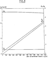
- the parameters W A , W B , Z A , and Z B are shown in FIG. 8 as a function of the viscous coefficient of friction.
- the coefficient c of the damper is proportional to the damping Z B of the frequency response of 12 Hz.
- this damping factor can be easily determined from a displacement or speed signal of the suspension travel.
- the coefficient c of the shock absorber can therefore easily be determined on the basis of relations (30) and (31).
- this signal processing allows the determination of the coefficient c of the shock absorber while being perfectly free from the amplitude of the road profile.
- test device according to the present invention as shown diagrammatically in FIG. 11.
- Each of the suspensions is equipped with a sensor 10, 11, 12, 13 adapted to generate an electrical signal representative of the oscillations of the suspension.
- This sensor can equally be a force sensor, composed for example of a piezoelectric cell, interposed between the suspension spring and the suspended masses or the unsprung masses, a sensitive sensor or relative displacement of suspended masses / unsprung masses, by example formed by a piezoelectric cell arranged between two turns of the suspension spring, in the case of a coil spring, a force sensor placed on the shock absorber of the suspension, or even an accelerometer placed on the unsprung masses .
- a force sensor composed for example of a piezoelectric cell, interposed between the suspension spring and the suspended masses or the unsprung masses
- a sensitive sensor or relative displacement of suspended masses / unsprung masses by example formed by a piezoelectric cell arranged between two turns of the suspension spring, in the case of a coil spring, a force sensor placed on the shock absorber of the suspension, or even an accelerometer placed on the unsprung masses .
- the electrical signals delivered by the sensors 10, 11, 12 and 13 are preferably applied to a multiplexing member 20 allowing processing in sequence, wheel by wheel, of the signals from the different sensors.
- each sensor 10, 11, 12, 13 can be associated with a specific processing chain.
- a filter cell 25 which is adapted to retain only the oscillations generated by the unsprung masses of the vehicle and the spring effect of the tire.
- the filter cell 25 is preferably a band pass cell adapted to eliminate the low frequency oscillations of the order of 1 Hz created by the suspended masses of the vehicle and the suspension spring, as well as the frequencies greater than the oscillations generated by the masses not suspended from the vehicle and the spring effect of the tire.
- the filtering means 25 may for example have a bandwidth ranging from 9 to 15 Hz.
- the electrical signals filtered by cell 25 are then applied to processing means 30. At these, the electrical signals are first stored in a memory 35.
- the processing means 30 calculate (step 40) the ratio 811/812 between two successive extrema of the stored signals.
- the processing means 30 then compare (step 50) the value of the ratios determined previously in step 40 with the limits of a predetermined range of values, preferably 1 and 3, to determine whether the ratios established in step 40 are included or not in this range.
- the calculated ratios are eliminated by the processing means 30 since they are considered to be non-significant, and in particular capable of being generated following an excitation of the periodic profile type which cannot be used in the context of the present invention.
- the processing means 30 then establish in step 70 the average of the values stored in the means 60.
- Comparison means 80 then determine the difference existing between each of the reports established by the processing means 30 in step 40 and the average resulting from the means 70.
- the report established by the processing means 30 in step 40 is validated and stored.
- step 90 a second average on the basis of the ratio values not eliminated in step 80.
- step 90 The value of this average established by the processing means 30 in step 90 is used to determine in step 95 the value of a parameter representative of the viscous coefficient of friction c of the damper.
- the value of the parameter sought c is determined on the basis of the relation (32) in which S " / S, 2 represents the value of the average established by the processing means 30 in step 90.
- the value of the desired parameter c can be obtained using a correspondence table between the extrema ratios S 11 / S 12 on the one hand and the value sought of the parameter on the other hand.
- This correspondence table can be defined either using the above-mentioned relation (32) or on the basis of an approximation of the curve defined by this relation in the form of a succession of linear segments of different slopes.
- This alarm detection and display step can consist of comparing the value of the aforementioned parameter c with a threshold value and displaying an alarm when the calculated value of the coefficient of friction c falls below the threshold value, either to be viewed directly analog information representative of the viscous friction coefficient c.
- the parameter representative of the coefficient c can in particular be determined on the basis of extrema which are not successive, by adapting accordingly the relation (32), or the correspondence table used.
- the present invention can in particular be applied for controlling slave suspensions, for example for controlling the hardness of the suspension, in particular for compensation for wear.
- the display means 100 are adapted to deliver specific information for each of the suspensions, either in the form of an alarm indicator in the case of a comparison with a threshold value as previously mentioned, or in the form of an analog display of each of the measured coefficients c.
Landscapes
- Engineering & Computer Science (AREA)
- Mechanical Engineering (AREA)
- Physics & Mathematics (AREA)
- General Physics & Mathematics (AREA)
- General Engineering & Computer Science (AREA)
- Human Computer Interaction (AREA)
- Vehicle Body Suspensions (AREA)
Description
La présente invention concerne le contrôle de la suspension des véhicules automobiles.The present invention relates to the control of the suspension of motor vehicles.
On sait que les suspensions de véhicules automobiles sont généralement composées, pour chacune des roues, d'un ensemble, formé d'un amortisseur relié en parallèle à un ressort, disposé entre les masses suspendues et les masses non suspendues du véhicule.It is known that the suspensions of motor vehicles are generally composed, for each of the wheels, of an assembly, formed of a damper connected in parallel to a spring, disposed between the suspended masses and the unsprung masses of the vehicle.
On entend par masses suspendues l'ensemble des parties de la caisse du véhicule qui reposent sur la suspension ; tandis que l'on entend par masses non suspendues l'ensemble des masses mobiles par rapport à la caisse, et en particulier les roues et triangles de suspension. Le cas échéant, les masses non suspendues comprennent également les freins et une partie des amortisseurs.“Suspended masses” means all of the parts of the vehicle body which rest on the suspension; while non-suspended masses are understood to be all of the masses that are movable relative to the body, and in particular the wheels and suspension triangles. Where appropriate, the unsprung masses also include the brakes and part of the shock absorbers.
Le ressort de la suspension a pour fonction première de limiter la propagation, vers la caisse du véhicule, des mouvements verticaux des roues, afin d'accroître le confort routier.The primary function of the suspension spring is to limit the spread of vertical wheel movements to the vehicle body, in order to increase road comfort.
Néanmoins, après avoir encaissé une irrégularité de la route le ressort ne retrouve pas rapidement sa position d'équilibre stable. L'énergie qu'il a emmagasinée tend à induire des oscillations de la caisse ainsi que des chocs et rebonds de la roue sur le sol pendant lesquels cette énergie se dissipe en chaleur.However, after taking an irregularity in the road, the spring does not quickly return to its stable equilibrium position. The energy which it has stored tends to induce oscillations of the body as well as shocks and rebounds of the wheel on the ground during which this energy dissipates in heat.
Pour éviter cet inconvénient, on a proposé depuis longtemps de placer en parallèle du ressort un amortisseur dont le rôle est précisément de dissiper l'énergie emmagasinée dans le ressort, donc d'empêcher la création de mouvements parasites nocifs pour la qualité du confort et de la tenue de route.To avoid this drawback, it has long been proposed to place a shock absorber in parallel with the spring, the role of which is precisely to dissipate the energy stored in the spring, thus to prevent the creation of parasitic movements harmful to the quality of comfort and handling.
L'amortisseur le plus couramment usité se compose d'un corps lié rigidement aux masses non suspendues, qui définit une chambre principale remplie d'un fluide hydraulique, d'une tige coulissante, liée rigidement à la caisse du véhicule et à un piston percé de trous calibrés et équipés de clapets, qui se déplace dans la chambre principale, et d'une chambre secondaire, dite de compensation, remplie partiellement de gaz et de fluide hydraulique, qui communique avec la chambre principale par l'intermédiaire de clapets.The most commonly used shock absorber consists of a body rigidly connected to the unsprung masses, which defines a main chamber filled with hydraulic fluid, a sliding rod, rigidly linked to the body of the vehicle and to a pierced piston. calibrated holes fitted with valves, which moves in the main chamber, and a secondary chamber, called a compensation chamber, partially filled with gas and hydraulic fluid, which communicates with the main chamber via valves.
Néanmoins, d'autres types d'amortisseurs pour suspension de véhicules ont été proposés.However, other types of shock absorbers for vehicle suspension have been proposed.
La présente invention n'est pas limitée à un type d'amortisseur particulier.The present invention is not limited to a particular type of shock absorber.
La fonction de l'amortisseur est donc de transformer en chaleur l'énergie mécanique de mouvement de sa tige. Pour cela, l'amortisseur oppose au mouvement de sa tige une force sensiblement proportionnelle à la vitesse de cette dernière.The function of the shock absorber is therefore to transform the mechanical energy of movement of its rod into heat. For this, the shock absorber opposes the movement of its rod a force substantially proportional to the speed of the latter.
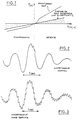
On a représenté schématiquement, sur la figure 1 annexée, la courbe : force appliquée sur la tige/vitesse, d'un amortisseur.There is shown schematically, in Figure 1 attached, the curve: force applied to the rod / speed, of a damper.
Chaque partie de cette courbe, force appliquée sur la tige/vitesse de la tige, correspondant respectivement à la détente et à la compression de l'amortisseur, comporte deux zones.Each part of this curve, force applied to the rod / speed of the rod, corresponding respectively to the rebound and to the compression of the shock absorber, has two zones.
La zone de courbe linéaire correspond aux conditions de fonctionnement où le fluide hydraulique circule par les clapets.The linear curve area corresponds to the operating conditions where the hydraulic fluid circulates through the valves.
Quand la vitesse de la tige diminue la pression du fluide atteint une valeur seuil au-dessous de laquelle les clapets ne peuvent plus fonctionner. Le fluide hydraulique circule alors par les orifices calibrés. Cela correspond à la seconde zone de la courbe, de type parabolique.When the speed of the rod decreases the pressure of the fluid reaches a threshold value below which the valves can no longer function. The hydraulic fluid then flows through the calibrated orifices. This corresponds to the second zone of the curve, of the parabolic type.
On sait néanmoins que le vieillissement a pour effet de diminuer la viscosité du fluide hydraulique et d'abaisser progressivement l'efficacité des multiples étanchéités de l'amortisseur, notamment au niveau des joints et clapets.However, it is known that aging has the effect of reducing the viscosity of the hydraulic fluid and progressively lowering the efficiency of the multiple seals of the damper, in particular at the seals and valves.
Cela provoque bien sûr un affaissement de la caractéristique force/vitesse. Cet affaissement peut d'ailleurs apparaître uniquement sur une des zones de la courbe (zone linéaire ou parabolique) avant de s'étendre aux suivantes.This of course causes the force / speed characteristic to collapse. This subsidence can also appear only on one of the areas of the curve (linear or parabolic area) before extending to the following.
On sait par ailleurs que l'état de la suspension influence dans une large mesure la tenue de route du véhicule.We also know that the state of the suspension has a large influence on the handling of the vehicle.
Il est donc souhaitable de disposer de moyens permettant de contrôler la suspension des véhicules.It is therefore desirable to have means for controlling the suspension of vehicles.
De nombreux moyens de contrôle à cet effet ont déjà été proposés. Toutefois, ces moyens ne donnent pas pleinement satisfaction.Numerous means of control for this purpose have already been proposed. However, these means are not fully satisfactory.
On a ainsi proposé, comme décrit dans le brevet US-A-2 923 147 et dans le brevet Italien 431 283, des moyens de contrôle mécaniques. L'utilisation de ces moyens est cependant limitée aux garages d'entretien. De plus, ces moyens ne permettent qu'un contrôle statique. Enfin, ces moyens ne permettent pas un contrôle fréquent voire continu de la suspension. Au mieux, ces moyens mécaniques sont utilisés généralement à une fréquence de l'ordre de une fois par an.Thus, as described in US-A-2,923,147 and in Italian patent 431,283, mechanical control means have been proposed. The use of these means is however limited to maintenance garages. In addition, these means only allow static control. Finally, these means do not allow frequent or even continuous monitoring of the suspension. At best, these mechanical means are generally used at a frequency of the order of once a year.
On a également proposé, comme décrit dans les brevets US-A-3 921 945 et US-A-3 937 152, des moyens de détection des vibrations d'un véhicule. Cette disposition ne permet pas cependant de réaliser un contrôle précis et fiable.We have also proposed, as described in patents US-A-3,921,945 and US-A-3,937,152, means for detecting the vibrations of a vehicle. However, this arrangement does not allow precise and reliable control.
On a également proposé, comme décrit dans les brevets GB-A-1 483 231 et US-A-4317105, des moyens sensibles à l'accélération du véhicule dans la direction verticale. Là encore, cependant, les dispositions de ce type jusqu'ici proposées ne permettent pas de réaliser un contrôle précis et fiable.There have also been proposed, as described in the patents GB-A-1 483 231 and US-A-4317105, means sensitive to the acceleration of the vehicle in the vertical direction. Again, however, the provisions of this type hitherto proposed do not allow for precise and reliable control.
On a également proposé, comme décrit dans le brevet GB-A-1 508 527, de comparer les caractéristiques force et vitesse d'un amortisseur en utilisant deux capteurs sensibles respectivement à ces données. Les moyens de test décrits dans ce document ne permettent pas cependant de contrôler de façon précise et fiable l'ensemble de la courbe force/vitesse.It has also been proposed, as described in GB-A-1 508 527, to compare the force and speed characteristics of a damper using two sensors sensitive respectively to these data. The test means described in this document do not, however, allow the entire force / speed curve to be checked precisely and reliably.
On a également proposé, comme décrit dans les brevets US-A-3 833 094 et US-A-3 646 512 d'utiliser des détecteurs de surcharge. Ces dispositifs ne permettent qu'une détection du type tout ou rien et ne permettent pas de renseigner sur l'état de la suspension.It has also been proposed, as described in patents US-A-3,833,094 and US-A-3,646,512 to use overload detectors. These devices only allow detection of the all or nothing type and do not provide information on the state of the suspension.
On a également proposé d'utiliser des jauges de contrainte pour mesurer les forces exercées en divers points de la suspension. De tels dispositifs sont par exemple décrits dans les brevets US-A-4 458 234, DE-A-2 351 862 et DE-A-2 341 423. Ces documents cependant se contentent d'évoquer, pour l'exploitation des signaux électriques délivrés par les jauges, l'agencement de ces jauges en pont ou encore la mesure des variations d'amplitude, positives ou négatives, des forces exercées sur l'amortisseur et/ou le ressort. Ces dispositions ne délivrent qu'une information globale sur le fonctionnement de la suspension et ne permettent pas de délivrer une information précise et fiable sur l'état de la suspension utile au conducteur.It has also been proposed to use strain gauges to measure the forces exerted at various points of the suspension. Such devices are for example described in patents US-A-4,458,234, DE-A-2,351,862 and DE-A-2,341,423. These documents, however, are content to evoke, for the exploitation of electrical signals delivered by the gauges, the arrangement of these gauges in bridge or even the measurement of the amplitude variations, positive or negative, of the forces exerted on the damper and / or the spring. These provisions only provide overall information on the operation of the suspension and do not make it possible to deliver precise and reliable information on the state of the suspension useful to the driver.
On a également proposé, comme décrit dans le document DE-A-2362661, de générer à l'aide d'un capteur un signal électrique représentatif des oscillations de la suspension, de filter le signal électrique pour retenir certaines fréquences seulement de celui-ci, puis de faire le quotient d'extrêma du signal retenu et de comparer ce quotient à une référence.It has also been proposed, as described in document DE-A-2362661, to generate, using a sensor, an electrical signal representative of the oscillations of the suspension, to filter the electrical signal to retain only certain frequencies thereof , then make the extreme quotient of the signal retained and compare this quotient with a reference.
Le problème posé est de concevoir une technique de mesure permettant de détecter de façon fiable, économique et continue, à l'aide de moyens embarcables, l'état de la suspension.The problem posed is to design a measurement technique making it possible to detect reliably, economically and continuously, using boatable means, the state of the suspension.
L'un des buts principaux de la présente invention est de concevoir des moyens de mesure économiques, appropriés pour être installés en série sur les véhicules automobiles sans grêver de façon significative le prix de revient de ceux-ci.One of the main objects of the present invention is to design economic measurement means, suitable for being installed in series on motor vehicles without significantly increasing the cost price thereof.
Le problème ainsi posé est résolu selon la présente invention par la mise en oeuvre d'un procédé de contrôle de la suspension d'un véhicule qui comprend les étapes consistant à :
- i) générer à l'aide d'un capteur du signal électrique représentatif des oscillations de la suspension,
- ii) filtrer le signal électrique pour retenir uniquement les oscillations générées par les masses non suspendues du véhicule et l'effet du pneumatique (et notamment éliminer les oscillations basse fréquence créées par les masses suspendues du véhicule et le ressort de suspension),
- iii) déterminer le rapport entre deux extréma du signal filtré, ce procédé étant caractérisé selon la présente invention par le fait que l'étape ii) de filtrage consiste à retenir uniquement les oscillations générées à une fréquence de l'ordre de 12 Hz, et à éliminer notamment les oscillations créées à une fréquence de l'ordre de 1 Hz, ainsi que les fréquences supérieures à 15 Hz, le procédé étant en outre. caractérisé par le fait qu'il comprend l'étape supplémentaire consistant à iv) déterminer la valeur d'un paramètre représentatif du coefficient de frottement visqueux de l'amortisseur sur la base de la relation :

- E et G représentent des constantes liées aux caractéristiques du véhicule et
- 8" et S12 représentent les amplitudes de deux extrema successifs.
- i) generate, using a sensor, an electrical signal representative of the oscillations of the suspension,
- ii) filter the electrical signal to retain only the oscillations generated by the unsprung masses of the vehicle and the effect of the tire (and in particular eliminate the low frequency oscillations created by the suspended masses of the vehicle and the suspension spring),
- iii) determining the ratio between two extremes of the filtered signal, this method being characterized according to the present invention by the fact that step ii) of filtering consists in retaining only the oscillations generated at a frequency of the order of 12 Hz, and to eliminate in particular the oscillations created at a frequency of the order of 1 Hz, as well as the frequencies greater than 15 Hz, the method being furthermore. characterized by the fact that it comprises the additional step consisting in iv) determining the value of a parameter representative of the viscous coefficient of friction of the damper on the basis of the relation:
- E and G represent constants related to the characteristics of the vehicle and
- 8 "and S 12 represent the amplitudes of two successive extrema.
Ce procédé est basé sur la démonstration théorique (qui sera rappelée dans la description détaillée qui va suivre) et la vérification expérimentale, établies par la Demanderesse, selon lesquelles, à la suite d'une excitation due au profil de la route, l'ensemble composé des masses suspendues du véhicule et du ressort de suspension génère une oscillation de base de basse fréquence, généralement de l'ordre de 1 Hz à laquelle se superpose une oscillation parasite de fréquence supérieure, généralement de l'ordre de 12 Hz, induite par l'ensemble composé des masses non suspendues du véhicule et de « l'effet ressort du pneumatique, mais, et c'est là une constatation essentielle, le taux d'amortissement des oscillations parasites dépend beaucoup plus de l'état de l'amortisseur, que le taux d'amortissement des oscillations de base.This process is based on the theoretical demonstration (which will be recalled in the detailed description which follows) and the experimental verification, established by the Applicant, according to which, following an excitation due to the profile of the road, the whole composed of the suspended masses of the vehicle and the suspension spring generates a basic oscillation of low frequency, generally of the order of 1 Hz to which is superimposed a parasitic oscillation of higher frequency, generally of the order of 12 Hz, induced by the whole composed of the unsprung masses of the vehicle and the "spring effect of the tire, but, and this is an essential observation, the rate of damping of parasitic oscillations depends much more on the state of the shock absorber , as the rate of depreciation of the basic oscillations.
En d'autres termes, un amortisseur en bon état atténue convenablement les oscillations parasites dues aux masses non suspendues du véhicule et à l'effet ressort du pneumatique. Par contre, un amortisseur présentant une usure n'atténue pas correctement ces oscillations parasites, et par conséquent n'évite pas les rebonds responsables du décollement. de la roue par rapport au sol, et de ce fait n'assure pas une tenue de route correcte.In other words, a damper in good condition suitably attenuates parasitic oscillations due to the unsprung masses of the vehicle and to the spring effect of the tire. On the other hand, a shock absorber exhibiting wear does not correctly attenuate these parasitic oscillations, and consequently does not avoid the rebounds responsible for detachment. of the wheel in relation to the ground, and therefore does not ensure correct handling.
L'influence de l'usure de l'amortisseur sur le niveau d'amortissement des oscillations de base de 1 Hz est en revanche moins nette.On the other hand, the influence of the wear of the shock absorber on the damping level of the basic oscillations of 1 Hz is less clear.
En effet, le faible couplage mécanique entre les différents étages de la suspension évite toute perturbation des signaux de 12 Hz. Alors que par contre, chaque demi-essieu se trouvant influencé par son homologue par l'intermédiaire de la masse suspendue, cela crée des interférences dans les signaux de base de 1 Hz.Indeed, the weak mechanical coupling between the different stages of the suspension avoids any disturbance of the 12 Hz signals. While on the other hand, each half-axle being influenced by its counterpart through the suspended mass, this creates interference in basic 1 Hz signals.
Il est de plus avantageux d'utiliser des capteurs travaillant essentiellement dans les fréquences supérieures à 10 Hz, dans la mesure où de tels capteurs sont en général moins coûteux que ceux travaillant à des fréquences inférieures.It is more advantageous to use sensors working essentially in frequencies above 10 Hz, insofar as such sensors are generally less expensive than those working at lower frequencies.
Le cas échéant, l'étape ii) de filtrage peut être réalisée par le capteur lui-même travaillant dans une plage de fréquences étroite centrée sur la fréquence des oscillations générées par les masses non suspendues et l'effet ressort du pneumatique.If necessary, step ii) of filtering can be carried out by the sensor itself working in a narrow frequency range centered on the frequency of the oscillations generated by the unsprung masses and the spring effect of the tire.
Selon une variante de réalisation conforme à la présente invention, le paramètre déterminé à l'étape iv) peut être obtenu à l'aide d'une table de correspondance entre les rapports d'extrema S11 et S12 d'une part et la valeur recherchée du paramètre d'autre part.According to an alternative embodiment in accordance with the present invention, the parameter determined in step iv) can be obtained using a correspondence table between the extrema ratios S 11 and S 12 on the one hand and the sought value of the parameter on the other hand.
Cette table de correspondance peut être remplie, soit à l'aide de la relation (32) précitée, soit sur la base d'une approximation de la courbe définie par cette relation sous forme d'une succession de segments linéaires de pentes différentes.This correspondence table can be filled either with the aid of the above-mentioned relation (32) or on the basis of an approximation of the curve defined by this relation in the form of a succession of linear segments of different slopes.
Ces deux variantes de réalisation seront explicitées plus en détail par la suite.These two alternative embodiments will be explained in more detail below.
Selon une autre caractéristique préférentielle, le procédé de contrôle conforme à la présente invention comprend de plus l'étape intermédiaire consistant à éliminer les valeurs du rapport d'extrema S,,/S,2 établi à l'étape iii) qui ne sont pas comprises dans une gamme prédéterminée, de préférence entre 1 et 3.According to another preferred characteristic, the control method according to the present invention further comprises the intermediate step consisting in eliminating the values of the extrema ratio S ,, / S, 2 established in step iii) which are not within a predetermined range, preferably between 1 and 3.
Cette disposition permet en particulier d'éliminer les réponses dues à une excitation du type profil périodique tel que des pavés, et de ne retenir que la réponse due à une excitation du genre profil occasionnel assimilable à la fonction créneau, tel que la marche d'un trottoir.This arrangement makes it possible in particular to eliminate the responses due to an excitation of the periodic profile type such as paving stones, and to retain only the response due to an excitation of the occasional profile type assimilable to the niche function, such as walking. a sidewalk.
Pour améliorer la précision de la mesure, le procédé de contrôle conforme à la présente invention comprend de préférence la réitération de l'étape iii) pour une pluralité de paire d'extrema successifs et l'établissement d'une moyenne de l'ensemble des rapports obtenus.To improve the accuracy of the measurement, the control method according to the present invention preferably comprises repeating step iii) for a plurality of successive pairs of extrema and establishing an average of all of the reports obtained.
De préférence, pour améliorer encore la précision de la mesure, le procédé de test conforme à la présente invention comprend en outre l'étape consistant à éliminer les valeurs de rapports d'extrema qui s'écartent de la moyenne de l'ensemble des rapports obtenus, d'au moins une valeur de tolérance prédéterminée, et à établir une seconde moyenne sur la base des rapports non éliminés.Preferably, to further improve the accuracy of the measurement, the test method according to the present invention further comprises the step of eliminating the values of extrema ratios which deviate from the average of all the ratios obtained, at least a predetermined tolerance value, and to establish a second average on the basis of the reports not eliminated.
Selon une autre caractéristique avantageuse de l'invention, le procédé conforme à la présente invention compred de plus l'étape supplémentaire consistant à comparer la valeur du paramètre établi à l'étape iv) avec une valeur de seuil et à afficher une alarme lorsque la valeur du paramètre tombe en dessous de la valeur seuil.According to another advantageous characteristic of the invention, the method according to the present invention further comprises the additional step of comparing the value of the parameter established in step iv) with a threshold value and of displaying an alarm when the parameter value falls below the threshold value.
Selon une autre variante, le procédé de contrôle conforme à la présente invention comprend l'étape supplémentaire consistant à exploiter, par exemple en visualisant, une information analogique liée à la valeur du paramètre déterminé à l'étape iv).According to another variant, the control method in accordance with the present invention comprises the additional step of exploiting, for example by viewing, analog information linked to the value of the parameter determined in step iv).
La présente invention concerne de plus un dispositif de contrôle pour la mise en oeuvre du procédé précité et une application.The present invention further relates to a control device for the implementation of the above method and an application.
D'autres caractéristiques et avantages de la présente invention apparaîtront à la lecture de la description détaillés qui va suivre, et en regard des dessins annexés donnés à titre d'exemple non limitatif et sur lesquels :
- - la figure 1 représente schématiquement la caractéristique force/vitesse d'un amortisseur,
- - la figure 2 représente le signal électrique mesuré en sortie d'un capteur disposé sur un ressort de suspension associé à un amortisseur en état de fonctionnement correct, lors du franchissement d'un raccord de goudron à une vitesse de 80 Km/h.
- - la figure 3 représente le signal électrique mesuré en sortie d'un capteur de déplacement similaire fixé sur le ressort d'une suspension comportant un amortisseur hors service, lors du franchissement du même raccord de goudron à la vitesse de 80 Km/h,
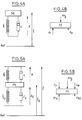
- - les figures 4A et 4B représentent schématiquement la modélisation des masses suspendues du véhicule,
- - les figures 5A et 5B représentent schématiquement la modélisation des masses non suspendues du véhicule,
- - la figure 6 représente schématiquement la réponse d'un capteur placé sur le ressort de la suspension, à la suite d'une excitation du type profil occasionnel,
- - la figure 7 représente schématiquement le signal obtenu après filtrage, d'une fréquence de l'ordre de 12 Hz due aux masses non suspendues du véhicule et à l'effet ressort du pneumatique,
- - les figures 8, 9 et 10 représentent diverses courbes qui seront explicitées dans le détail par la suite, et
- - la figure 11 représente une vue schématique du dispositif conforme à la présente invention.
- FIG. 1 diagrammatically represents the force / speed characteristic of a shock absorber,
- - Figure 2 shows the electrical signal measured at the output of a sensor arranged on a suspension spring associated with a shock absorber in correct working condition, when crossing a tar connection at a speed of 80 km / h.
- FIG. 3 represents the electrical signal measured at the output of a similar displacement sensor fixed on the spring of a suspension comprising an out-of-service damper, when crossing the same tar connection at the speed of 80 km / h,
- FIGS. 4A and 4B schematically represent the modeling of the suspended masses of the vehicle,
- FIGS. 5A and 5B schematically represent the modeling of the unsprung masses of the vehicle,
- FIG. 6 schematically represents the response of a sensor placed on the spring of the suspension, following an excitation of the occasional profile type,
- FIG. 7 schematically represents the signal obtained after filtering, with a frequency of the order of 12 Hz due to the unsprung masses of the vehicle and to the spring effect of the tire,
- FIGS. 8, 9 and 10 represent various curves which will be explained in detail below, and
- - Figure 11 shows a schematic view of the device according to the present invention.
La même échelle a été utilisée pour la représentation des figures 2 et 3.The same scale was used for the representation of Figures 2 and 3.
Une simple comparaison des signaux illustrés sur ces figures montre que, comme cela était précédemment indiqué, le taux d'amortissement des oscillations parasites de 12 Hz dépend beaucoup plus de l'état de l'amortisseur que le taux d'amortissement des oscillations de base de 1 Hz.A simple comparison of the signals illustrated in these figures shows that, as previously indicated, the damping rate of the parasitic oscillations of 12 Hz depends much more on the state of the damper than the damping rate of the
En effet, ces oscillations de base possèdent sensiblement la même amplitude sur les figures 2 et 3 ce qui signifie que l'état de l'amortisseur influence peu le niveau d'atténuation des oscillations de base.In fact, these basic oscillations have substantially the same amplitude in FIGS. 2 and 3, which means that the state of the damper has little influence on the level of attenuation of the basic oscillations.
Par contre, on remarquera que si pour un amortisseur en état de fonctionnement normal, les oscillations parasites de 12 Hz sont quasi-totalement amorties, comme représenté sur la figure 2, par contre, dans le cas d'un amortisseur hors service, comme illustré sur la figure 3, l'amplitude des oscillations parasites de 12 Hz est non négligeable.On the other hand, it will be noted that if for a damper in normal operating condition, the parasitic oscillations of 12 Hz are almost completely damped, as shown in FIG. 2, on the other hand, in the case of a damper out of service, as illustrated in FIG. 3, the amplitude of the parasitic oscillations of 12 Hz is not negligible.
La demanderesse a par ailleurs appuyé ses constatations expérimentales par une démonstration théorique que l'on va expliciter par la suite pour la bonne compréhension de la présente invention.The Applicant has also supported its experimental findings with a theoretical demonstration which will be explained below for the proper understanding of the present invention.
L'analyse théorique qui suit est basée d'une part sur l'exploitation d'un modèle de courbe force/allongement d'allure linéaire pour le ressort, c'est-à-dire un modèle répondant à la relation :
- (1) Fr = - k . A1 dans laquelle Fr rerpésente la force développée par le ressort,
- k représente la raideur du ressort, et A1 représente l'allongement du ressort, et d'autre part sur l'exploitation d'un modèle de courbe force/vitesse, d'allure linéaire et de même pente quelle que soit la phase d'utilisation, compression ou détente, pour l'amortisseur, c'est-à-dire un modèle répondant à la relation :
- (2) Fa = - c . v dans laquelle Fa représente la force développée par l'amortisseur,
- c représente le coefficient de frottement visqueux, et
- v représente la vitesse de la tige.
- (1) F r = - k. A 1 in which F r represents the force developed by the spring,
- k represents the stiffness of the spring, and A 1 represents the elongation of the spring, and on the other hand on the exploitation of a model of force / speed curve, of linear pace and of the same slope whatever the phase d '' use, compression or relaxation, for the shock absorber, i.e. a model corresponding to the relation:
- (2) F a = - c. v in which F a represents the force developed by the damper,
- c represents the coefficient of viscous friction, and
- v represents the speed of the rod.
Le bilan des forces exercées au niveau des masses suspendues (schématisées sur les figures 4A, 4B) permet d'écrire d'une part en statique :
- M représente la valeur de la masse suspendue
- Ao représente l'élongation du ressort au repos et
- A1 représente l'allongement du ressort dû à la masse suspendue, d'autre part en dynamique :


- x représente le déplacement de la masse suspendue, et
- x2 représente le déplacement de la masse non suspendue.
- M represents the value of the suspended mass
- A o represents the elongation of the spring at rest and
- A 1 represents the elongation of the spring due to the suspended mass, on the other hand in dynamics:
- x represents the displacement of the suspended mass, and
- x 2 represents the displacement of the unsprung mass.
Par ailleurs le bilan des forces exercées au niveau des masses non suspendues (schématisées sur les figures 5A, 5B) permet d'écrire, d'une part en statique :
- Fr2 représente la force exercée sur la masse non suspendue résultant de l'élasticité du pneumatique,
- Fa2 représente la force exercée sur la masse non suspendue résultant de l'effet d'amortisseur dû aux fibres du pneumatique,
- k2 représente la raideur du pneumatique
- A20 représente l'élongation au repos de l'élément ressort formé par le pneumatique, et
- A12 représente l'allongement de cet élément dû aux masses mises en jeu, d'autre part en dynamique :


- 12 représente la hauteur de la masse non suspendue,
- x2 représente le déplacement de la masse non suspendue,
- c2 représente le coefficient de frottement visqueux et l'effet d'amortisseur dû aux fibres du pneumatique, et
- x1 représente le déplacement du pneumatique.
- F r2 represents the force exerted on the unsprung mass resulting from the elasticity of the tire,
- F a2 represents the force exerted on the unsprung mass resulting from the damping effect due to the fibers of the tire,
- k 2 represents the stiffness of the tire
- A 20 represents the elongation at rest of the spring element formed by the tire, and
- A1 2 represents the elongation of this element due to the masses involved, on the other hand in dynamics:
- 1 2 represents the height of the unsprung mass,
- x 2 represents the displacement of the unsprung mass,
- c 2 represents the coefficient of viscous friction and the damping effect due to the fibers of the tire, and
- x 1 represents the displacement of the tire.
En posant :
-

-

- = pulsation propre du demi-essieu par rapport à la masse suspendue,
- coefficient d'amortissement du demi-essieu par rapport la masse suspendue, coefficient d'amortissement du demi-essieu par rapport à la masse suspendue,
- = pulsation propre du demi-essieu par rapport au sol,
- = coefficient d'amortissement du demi-essieu par rapport au sol, les équations (5) et (8) s'écrivent :


-
-
- = own pulsation of the half-axle in relation to the suspended mass,
- damping coefficient of the half-axle with respect to the suspended mass, damping coefficient of the half-axle with respect to the suspended mass,
- = proper pulsation of the half-axle relative to the ground,
- = damping coefficient of the half-axle compared to the ground, equations (5) and (8) are written:
En utilisant les transformées de Laplace, les équations (9) et (10) s'écrivent alors :![]()
![]()
![]()
![]()
![]()
![]()
![]()
![]()
![]()
![]()
![]()
![]()
![]()
![]()
Les formules (13) et (14) donnent donc les évolutions du mouvement de la caisse (X) et du mouvement de la roue (X2) par rapport à une référence absolue et en fonction du profil de la route (X1).The formulas (13) and (14) therefore give the changes in the movement of the body (X) and the movement of the wheel (X 2 ) with respect to an absolute reference and as a function of the profile of the road (X 1 ).
Le calcul montre que les quatre racines du dénominateur D (17) sont des nombres complexes conjugués deux à deux.The calculation shows that the four roots of the denominator D (17) are complex numbers conjugated two by two.
Ceci exprime que le filtre mécanique que réalise la suspension peut se décomposer en deux filtres du second ordre.This expresses that the mechanical filter produced by the suspension can be broken down into two second order filters.
Par ailleurs un calcul numérique montre que ces deux filtres possèdent des fréquences de coupure se situant aux alentours de 1 Hz et de 12 Hz.In addition, a numerical calculation shows that these two filters have cut-off frequencies around 1 Hz and 12 Hz.
La fréquence de coupure de 1 Hz est créée par les masses suspendues du véhicule et le ressort de suspension.The cut-off frequency of 1 Hz is created by the suspended masses of the vehicle and the suspension spring.
La fréquence de coupure de 12 Hz est générée par les masses non suspendues du véhicule et l'effet ressort du pneumatique.The cutoff frequency of 12 Hz is generated by the unsprung masses of the vehicle and the spring effect of the tire.
Dans le cas d'une excitation de la suspension par un profil occasionnel assimilable à la fonction créneau susceptible d'engendrer une variation brutale de l'écrasement du ressort, tel qu'une marche de trottoir, le déplacement de la suspension répond à la relation suivante, en se déplaçant dans le domaine temporel :
- A représente l'amplitude de l'excitation
- d1 représente la longueur de l'excitation
- v représente la vitesse du véhicule
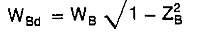
- ZA, ZB représentent les facteurs d'amortissement de chacun des filtres,
- WA, WB représentent les pulsations de coupure de chacun des filtres,
- ϕ1, ϕ2 représentent les déphasages des signaux

- B1, B2 représentent les coefficients d'amplitude.
- A represents the amplitude of the excitation
- d 1 represents the length of the excitation
- v represents the speed of the vehicle
- Z A , Z B represent the damping factors of each of the filters,
- W A , W B represent the cut-off pulses of each of the filters,
- ϕ 1 , ϕ 2 represent the phase shifts of the signals
- B 1 , B 2 represent the amplitude coefficients.
On a représenté schématiquement sur les figures 6 et 7 les signaux s(t) et s2(t).The signals s (t) and s 2 (t) are shown diagrammatically in FIGS. 6 and 7.
Les paramètres WA, WB, ZA, et ZB sont représentés sur la figure 8 en fonction du coefficient de frottement visqueux.The parameters W A , W B , Z A , and Z B are shown in FIG. 8 as a function of the viscous coefficient of friction.
Par ailleurs, on montre que le coefficient B2 correspondant au signal parasite de 12 Hz est bien supérieur à celui B1 du signal de base, comme illustré sur la figure 9 qui illustre ces paramètres en fonction du coefficient de frottement visqueux.Furthermore, it is shown that the coefficient B 2 corresponding to the parasitic signal of 12 Hz is much higher than that B 1 of the basic signal, as illustrated in FIG. 9 which illustrates these parameters as a function of the coefficient of viscous friction.
En effet,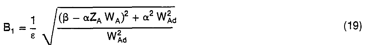

![]()
![]()
![]()
![]()
![]()
![]()
![]()
![]()
![]()
![]()
En faisant les approximations suivantes, justifiées par le tracé des courbes sur la figure 8 :![]()
![]()
![]()
![]()
![]()
![]()
![]()
![]()
On obtient à partir des équations précédentes :![]()
![]()
On remarque donc que le coefficient c de l'amortisseur est proportionnel à l'amortissement ZB de la réponse de la fréquence de 12 Hz.It is therefore noted that the coefficient c of the damper is proportional to the damping Z B of the frequency response of 12 Hz.
Or ce facteur d'amortissement peut se déterminer facilement à partir d'un signal de déplacement ou de vitesse du débattement de la suspension.However, this damping factor can be easily determined from a displacement or speed signal of the suspension travel.
En appelant en effet S11 et S12 les amplitudes de deux extrema successifs du signal de 12 Hz, c'est-à-dire deux extrema successifs du second membre de la relation (18) on obtient :
Le coefficient c de l'amortisseur peut donc aisément être déterminé sur la base des relations (30) et (31).The coefficient c of the shock absorber can therefore easily be determined on the basis of relations (30) and (31).
La combinaison des relations (30) et (31) permet en effet d'obtenir la relation (32) précitée.The combination of relations (30) and (31) in fact makes it possible to obtain the above-mentioned relation (32).
On remarquera de plus que ce traitement de signal permet la détermination du coefficient c de l'amortisseur tout en s'affranchissant parfaitement de l'amplitude du profil de la route.It will also be noted that this signal processing allows the determination of the coefficient c of the shock absorber while being perfectly free from the amplitude of the road profile.
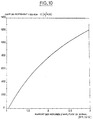
Le tracé de la courbe c en fonction du rapport S11/S12, sur la figure 10 annexée montre que le coefficient c présente un bon rapport de proportionnalité avec ce rapport S11/S12 et par conséquent le coefficient c peut être déterminé sur la base d'une approximation de cette courbe sous forme d'une succession de segments linéaires de pentes différentes.The plot of the curve c as a function of the ratio S 11 / S 12 , in the appended figure 10 shows that the coefficient c has a good proportionality relationship with this ratio S 11 / S 12 and therefore the coefficient c can be determined on the basis of an approximation of this curve in the form of a succession of linear segments of different slopes.
On va maintenant décrire le dispositif de test conforme à la présente invention tel qu'illustré schématiquement sur la figure 11.We will now describe the test device according to the present invention as shown diagrammatically in FIG. 11.
Chacune des suspensions est équipée d'un capteur 10, 11, 12, 13 adapté pour générer un signal électrique représentatif des oscillations de la suspension.Each of the suspensions is equipped with a
Ce capteur pourra indifféremment être un capteur de force, composé par exemple d'une cellule piézoélectrique, intercalé entre le ressort de la suspension et les masses suspendues ou les masses non suspendues, un capteur sensible ou déplacement relatif masses suspendues/masses non suspendues, par exemple formé d'une cellule piezoélectrique disposés entre deux spires du ressort de la suspension, dans le cas d'un ressort à boudin, un capteur de force placé sur l'amortisseur de la suspension, ou encore un accéléromètre placé sur les masses non suspendues.This sensor can equally be a force sensor, composed for example of a piezoelectric cell, interposed between the suspension spring and the suspended masses or the unsprung masses, a sensitive sensor or relative displacement of suspended masses / unsprung masses, by example formed by a piezoelectric cell arranged between two turns of the suspension spring, in the case of a coil spring, a force sensor placed on the shock absorber of the suspension, or even an accelerometer placed on the unsprung masses .
Les signaux électriques délivrés par les capteurs 10, 11, 12 et 13 sont de préférence appliqués à un organe de multiplexage 20 permettant d'opérer un traitement en séquence, roue par roue, des signaux issus des différents capteurs.The electrical signals delivered by the
Néanmoins, le cas échéant chaque capteur 10, 11, 12, 13 peut être associé à une chaîne de traitement spécifique.However, where appropriate, each
Ces signaux électriques sont appliqués à une cellule de filtrage 25 qui est adaptée pour retenir uniquement les oscillations générées par les masses non suspendues du véhicule et l'effet ressort du pneumatique.These electrical signals are applied to a
La cellule de filtrage 25 est de préférence une cellule passe bande adaptée pour éliminer les oscillations basse fréquence de l'ordre de 1 Hz créées par les masses suspendues du véhicule et le ressort de suspension, ainsi que les fréquences supérieures aux oscillations générées par les masses non suspendues du véhicule et l'effet ressort du pneumatique.The
Les moyens de filtrage 25 peuvent posséder par exemple une bande passante allant de 9 à 15 Hz.The filtering means 25 may for example have a bandwidth ranging from 9 to 15 Hz.
Les signaux électriques filtrés oar la cellule 25 sont ensuite appliqués à des moyens de traitement 30. Au niveau de ceux-ci les signaux électriques sont tout d'abord mémorisés dans une mémoire 35.The electrical signals filtered by
Les moyens de traitement 30 calculent (étape 40) le rapport 811/812 entre deux extrema successifs des signaux mémorisés.The processing means 30 calculate (step 40) the ratio 811/812 between two successive extrema of the stored signals.
Les moyens de traitement 30 comparent ensuite (étape 50) la valeur des rapports déterminés précédemment à l'étape 40 aux bomes d'une gamme prédéterminée de valeurs, de préférence 1 et 3, pour déterminer si les rapports établis à l'étape 40 sont compris ou non dans cette gamme.The processing means 30 then compare (step 50) the value of the ratios determined previously in
Dans la négative, les rapports calculés sont éliminés par les moyens de traitement 30 car considérés comme non significatifs, et notamment susceptibles d'être générés à la suite d'une excitation du type profil périodique non exploitable dans le cadre de la présente invention.If not, the calculated ratios are eliminated by the processing means 30 since they are considered to be non-significant, and in particular capable of being generated following an excitation of the periodic profile type which cannot be used in the context of the present invention.
Par contre, dans l'affirmative, c'est-à-dire dans le cas où les valeurs des rapports calculés à l'étape 40 sont comprises dans la gamme prédéterminée, les valeurs de ces rapports sont mémorisées dans des moyens 60.On the other hand, in the affirmative, that is to say in the case where the values of the ratios calculated in
Les moyens de traitement 30 établissent alors à l'étape 70 la moyenne des valeurs mémorisées dans les moyens 60.The processing means 30 then establish in
Des moyens de comparaison 80 déterminent ensuite l'écart existant entre chacun des rapports établis par les moyens de traitement 30 à l'étape 40 et la moyenne issue des moyens 70.Comparison means 80 then determine the difference existing between each of the reports established by the processing means 30 in
Si cet écart est inférieur à un seuil prédéterminé, le rapport établi par les moyens de traitement 30 à l'étape 40 est validé et mémorisé.If this difference is less than a predetermined threshold, the report established by the processing means 30 in
Par contre, si l'écart précité est supérieur au seuil prédéterminé, les valeurs de rapport correspondantes établies par les moyens de traitement 30 à l'étape 40 sont éliminées.On the other hand, if the aforementioned deviation is greater than the predetermined threshold, the corresponding ratio values established by the processing means 30 in
Puis les moyens de traitement 30 établissent à l'étape 90 une seconde moyenne sur la base des valeurs de rapport non éliminées à l'étape 80.Then the processing means 30 establish in step 90 a second average on the basis of the ratio values not eliminated in
La valeur de cette moyenne établie par les moyens de traitement 30 à l'étape 90 est utilisée pour déterminer à l'étape 95 la valeur d'un paramètre représentatif du coefficient de frottement visqueux c de l'amortisseur.The value of this average established by the processing means 30 in
Pour ce faire, selon une première variante de réalisation conforme à la présente invention, la valeur du paramètre recherché c est déterminée sur la base de la relation (32) dans laquelle S"/S,2 représente la valeur de la moyenne établie par les moyens de traitement 30 à l'étape 90.To do this, according to a first alternative embodiment in accordance with the present invention, the value of the parameter sought c is determined on the basis of the relation (32) in which S " / S, 2 represents the value of the average established by the processing means 30 in
Selon une seconde variante de réalisation conforme à la présente invention, la valeur du paramètre recherché c peut être obtenue à l'aide d'une table de correspondance entre les rapports d'extrema S11/S12 d'une part et la valeur recherchée du paramètre d'autre part.According to a second alternative embodiment in accordance with the present invention, the value of the desired parameter c can be obtained using a correspondence table between the extrema ratios S 11 / S 12 on the one hand and the value sought of the parameter on the other hand.
Cette table de correspondance peut être définie, soit à l'aide de la relation (32) précitée, soit sur la base d'une approximation de la courbe définie par cette relation sous forme d'une succession de segments linéaires de pentes différentes.This correspondence table can be defined either using the above-mentioned relation (32) or on the basis of an approximation of the curve defined by this relation in the form of a succession of linear segments of different slopes.
Les phases de traitement du signal précédemment décrites sont suivies d'une étape d'exploitation, comme par exemple une détection d'alarme et le cas échéant de visualisation sur des moyens 100.The signal processing phases described above are followed by an operating step, such as for example alarm detection and, if necessary, display on
Cette étape de détection d'alarme et de visualisation peut consister à comparer la valeur du paramètre précité c avec une valeur de seuil et afficher une alarme lorsque la valeur calculée du coefficient de frottement c tombe en dessous de la valeur seuil, soit à visualiser directement une information analogique représentative du coefficient de frottement visqueux c.This alarm detection and display step can consist of comparing the value of the aforementioned parameter c with a threshold value and displaying an alarm when the calculated value of the coefficient of friction c falls below the threshold value, either to be viewed directly analog information representative of the viscous friction coefficient c.
Bien entendu, la présente invention n'est pas limitée au mode de réalisation qui vient d'être décrit mais s'étend à toute variante conforme à ses revendications.Of course, the present invention is not limited to the embodiment which has just been described but extends to any variant according to its claims.
Le paramètre représentatif du coefficient c peut en particulier être déterminé sur la base d'extrema qui ne sont pas successifs, en adaptant en conséquence la relation (32), ou la table de correspondance utilisée.The parameter representative of the coefficient c can in particular be determined on the basis of extrema which are not successive, by adapting accordingly the relation (32), or the correspondence table used.
La présente invention peut en particulier être appliquée pour la commande de suspensions asservies, par exemple pour commander la dureté de la suspension notamment pour une compensation d'usure.The present invention can in particular be applied for controlling slave suspensions, for example for controlling the hardness of the suspension, in particular for compensation for wear.
De préférence, les moyens de visualisationn 100 sont adaptés pour délivrer une information spécifique pour chacune des suspensions, soit sous forme d'un témoin d'alarme dans le cas d'une comparaison avec une valeur seuil comme précédemment évoqué, soit sous forme d'un affichage analogique de chacun des coefficients c mesurés.Preferably, the display means 100 are adapted to deliver specific information for each of the suspensions, either in the form of an alarm indicator in the case of a comparison with a threshold value as previously mentioned, or in the form of an analog display of each of the measured coefficients c.
Claims (21)


Applications Claiming Priority (2)
| Application Number | Priority Date | Filing Date | Title |
|---|---|---|---|
| FR8515084A FR2588661B1 (en) | 1985-10-11 | 1985-10-11 | METHOD FOR MONITORING A VEHICLE SUSPENSION BY MEASURING THE DAMPING FACTOR OF AN OSCILLATORY SIGNAL OF THE SUSPENSION AND DEVICE FOR CARRYING OUT THIS METHOD. |
| FR8515084 | 1985-10-11 |
Publications (2)
| Publication Number | Publication Date |
|---|---|
| EP0220985A1 EP0220985A1 (en) | 1987-05-06 |
| EP0220985B1 true EP0220985B1 (en) | 1990-03-28 |
Family
ID=9323740
Family Applications (1)
| Application Number | Title | Priority Date | Filing Date |
|---|---|---|---|
| EP19860402253 Expired - Lifetime EP0220985B1 (en) | 1985-10-11 | 1986-10-10 | Process and device for checking a vehicle suspension by measuring the damping factor of an oscillating suspension signal |
Country Status (3)
| Country | Link |
|---|---|
| EP (1) | EP0220985B1 (en) |
| DE (1) | DE3669922D1 (en) |
| FR (1) | FR2588661B1 (en) |
Cited By (1)
| Publication number | Priority date | Publication date | Assignee | Title |
|---|---|---|---|---|
| EP3505903A1 (en) | 2017-12-30 | 2019-07-03 | EMT-Systems Sp.z o.o. | A method for detecting manufacturing defects of hydraulic dampers, especially shock absorbers, and a device for detecting manufacturing defects of hydraulic dampers, especially shock absorbers |
Families Citing this family (6)
| Publication number | Priority date | Publication date | Assignee | Title |
|---|---|---|---|---|
| DE8810344U1 (en) * | 1988-08-16 | 1988-12-01 | Gebr. Knechtli, Kleindöttingen | Electronic shock absorber tester |
| JP3042280B2 (en) * | 1993-10-28 | 2000-05-15 | トヨタ自動車株式会社 | Shock absorber oil temperature estimation device and damping force control device using the same |
| PT103847B (en) * | 2007-10-10 | 2011-06-24 | Universidade De Tras-Os-Montes E Alto Douro | CONTINUOUS MONITORING SYSTEM FOR APPLICATION ON DAMPERS |
| FR2958400B1 (en) * | 2010-04-02 | 2012-06-15 | Michelin Soc Tech | METHOD FOR CHARACTERIZING AND IMPROVING THE BEHAVIOR OF A VEHICLE |
| FR2961333B1 (en) * | 2010-06-14 | 2012-06-08 | Eurocopter France | METHOD FOR MONITORING THE EFFICIENCY OF A DAMPER AND DEVICE FOR CARRYING OUT SAID METHOD |
| CN110910531B (en) * | 2019-10-21 | 2020-10-20 | 同济大学 | Rapid pavement friction coefficient detection method based on vehicle-mounted OBD information |
Family Cites Families (3)
| Publication number | Priority date | Publication date | Assignee | Title |
|---|---|---|---|---|
| DE2334737A1 (en) * | 1973-07-09 | 1975-04-03 | Volkswagenwerk Ag | PROCEDURE FOR TESTING THE WORKABILITY OF SHOCK ABSORBERS |
| DE2905931C2 (en) * | 1979-02-16 | 1985-12-19 | Daimler-Benz Ag, 7000 Stuttgart | Device for monitoring shock absorbers and tire air pressure of vehicle wheels |
| FR2506014B1 (en) * | 1981-05-14 | 1987-08-21 | Brisard Gerard | ON-BOARD APPARATUS FOR CONTROLLING SUSPENSION SHOCK ABSORBERS |
-
1985
- 1985-10-11 FR FR8515084A patent/FR2588661B1/en not_active Expired
-
1986
- 1986-10-10 EP EP19860402253 patent/EP0220985B1/en not_active Expired - Lifetime
- 1986-10-10 DE DE8686402253T patent/DE3669922D1/en not_active Expired - Lifetime
Cited By (1)
| Publication number | Priority date | Publication date | Assignee | Title |
|---|---|---|---|---|
| EP3505903A1 (en) | 2017-12-30 | 2019-07-03 | EMT-Systems Sp.z o.o. | A method for detecting manufacturing defects of hydraulic dampers, especially shock absorbers, and a device for detecting manufacturing defects of hydraulic dampers, especially shock absorbers |
Also Published As
| Publication number | Publication date |
|---|---|
| DE3669922D1 (en) | 1990-05-03 |
| FR2588661B1 (en) | 1989-04-14 |
| EP0220985A1 (en) | 1987-05-06 |
| FR2588661A1 (en) | 1987-04-17 |
Similar Documents
| Publication | Publication Date | Title |
|---|---|---|
| EP0220115B1 (en) | Process and device for checking a vehicle suspension by measuring the friction coefficient of the damper | |
| EP0220985B1 (en) | Process and device for checking a vehicle suspension by measuring the damping factor of an oscillating suspension signal | |
| US7813850B2 (en) | System and method for shock absorber diagnostic | |
| FR2874205A1 (en) | Damper hardness controlling method for e.g. helicopter, involves adjusting hardness of damper of landing gear of aircraft during compression of damper according to inherent frequency of deformation of structure of aircraft | |
| FR2719000A1 (en) | Active suspension system, in particular for automobiles. | |
| FR2594922A1 (en) | METHOD FOR ADJUSTING THE DAMPING FORCE OF A SHOCK ABSORBER | |
| FR2863651A1 (en) | SYSTEM AND METHOD FOR DRILL TOOL SENSOR | |
| EP2817607B1 (en) | Measuring head intended to be fitted to a dynamic penetrometer and method of measurement using such a measuring head | |
| FR3002204A1 (en) | INSTRUMENT SHOCK ABSORBER AND PERFORMANCE MONITORING SYSTEM COMPRISING SUCH DAMPER. | |
| EP1571517A1 (en) | Control method for damping helicopter vibrations and device executing that method | |
| EP0657620B1 (en) | Method and system for the control of the "stick-slip" of a drill tool | |
| Eshkabilov et al. | Measuring and assessing road profile by employing accelerometers and IRI assessment tools | |
| CA2080483C (en) | Method for automatically monitoring the vibrational condition of a drill string | |
| EP0220116B1 (en) | Process and device for checking a vehicle suspension by measuring the friction coefficient of the damper | |
| EP0223653B1 (en) | Process and device for checking a vehicle suspension by checking the road-holding properties | |
| EP0736781A1 (en) | Low frequency seismic sensor | |
| FR2957306A3 (en) | Semi-active suspension damper for use between wheel and body shell of motor vehicle to damp vibrations occurred during moving vehicle, has control module delivering control signal to damper for controlling coefficient of damper | |
| Lozoya-Santos et al. | Fault detection for an automotive MR damper | |
| CN112413030A (en) | Shock absorber damping control and performance evaluation method, shock absorber optimized by using same and vehicle adopting shock absorber | |
| FR2929664A1 (en) | METHOD FOR CONTROLLING A HYDRAULIC ACTUATOR | |
| EP0483016A1 (en) | Procedure and apparatus for controlling the efficiency of a suspension in situ | |
| FR3046571A1 (en) | DEVICE FOR MANAGING THE ROLL ON A PENDULAR MOTOR VEHICLE | |
| EP1502775A1 (en) | Method for evaluating the tyres pressure and vehicle having a pressure monitoring device able to apply such a method | |
| FR2693273A1 (en) | Measuring acceleration of vehicle | |
| Van Vliet et al. | Computer-aided analysis and experimental verification of a motorcycle suspension |
Legal Events
| Date | Code | Title | Description |
|---|---|---|---|
| PUAI | Public reference made under article 153(3) epc to a published international application that has entered the european phase |
Free format text: ORIGINAL CODE: 0009012 |
|
| AK | Designated contracting states |
Kind code of ref document: A1 Designated state(s): DE GB IT |
|
| 17P | Request for examination filed |
Effective date: 19870921 |
|
| 17Q | First examination report despatched |
Effective date: 19881110 |
|
| GRAA | (expected) grant |
Free format text: ORIGINAL CODE: 0009210 |
|
| AK | Designated contracting states |
Kind code of ref document: B1 Designated state(s): DE GB IT |
|
| PG25 | Lapsed in a contracting state [announced via postgrant information from national office to epo] |
Ref country code: IT Free format text: LAPSE BECAUSE OF FAILURE TO SUBMIT A TRANSLATION OF THE DESCRIPTION OR TO PAY THE FEE WITHIN THE PRESCRIBED TIME-LIMIT;WARNING: LAPSES OF ITALIAN PATENTS WITH EFFECTIVE DATE BEFORE 2007 MAY HAVE OCCURRED AT ANY TIME BEFORE 2007. THE CORRECT EFFECTIVE DATE MAY BE DIFFERENT FROM THE ONE RECORDED. Effective date: 19900328 Ref country code: GB Effective date: 19900328 |
|
| REF | Corresponds to: |
Ref document number: 3669922 Country of ref document: DE Date of ref document: 19900503 |
|
| GBV | Gb: ep patent (uk) treated as always having been void in accordance with gb section 77(7)/1977 [no translation filed] | ||
| PLBE | No opposition filed within time limit |
Free format text: ORIGINAL CODE: 0009261 |
|
| STAA | Information on the status of an ep patent application or granted ep patent |
Free format text: STATUS: NO OPPOSITION FILED WITHIN TIME LIMIT |
|
| 26N | No opposition filed | ||
| PGFP | Annual fee paid to national office [announced via postgrant information from national office to epo] |
Ref country code: DE Payment date: 19921121 Year of fee payment: 7 |
|
| PG25 | Lapsed in a contracting state [announced via postgrant information from national office to epo] |
Ref country code: DE Effective date: 19940701 |