EP0220769A1 - Process for the manufacture of a cylindrical type high-temperature spring - Google Patents
Process for the manufacture of a cylindrical type high-temperature spring Download PDFInfo
- Publication number
- EP0220769A1 EP0220769A1 EP86201815A EP86201815A EP0220769A1 EP 0220769 A1 EP0220769 A1 EP 0220769A1 EP 86201815 A EP86201815 A EP 86201815A EP 86201815 A EP86201815 A EP 86201815A EP 0220769 A1 EP0220769 A1 EP 0220769A1
- Authority
- EP
- European Patent Office
- Prior art keywords
- tube
- recesses
- spring
- hollow cylindrical
- producing
- Prior art date
- Legal status (The legal status is an assumption and is not a legal conclusion. Google has not performed a legal analysis and makes no representation as to the accuracy of the status listed.)
- Granted
Links
Images


Classifications
-
- C—CHEMISTRY; METALLURGY
- C04—CEMENTS; CONCRETE; ARTIFICIAL STONE; CERAMICS; REFRACTORIES
- C04B—LIME, MAGNESIA; SLAG; CEMENTS; COMPOSITIONS THEREOF, e.g. MORTARS, CONCRETE OR LIKE BUILDING MATERIALS; ARTIFICIAL STONE; CERAMICS; REFRACTORIES; TREATMENT OF NATURAL STONE
- C04B35/00—Shaped ceramic products characterised by their composition; Ceramics compositions; Processing powders of inorganic compounds preparatory to the manufacturing of ceramic products
- C04B35/01—Shaped ceramic products characterised by their composition; Ceramics compositions; Processing powders of inorganic compounds preparatory to the manufacturing of ceramic products based on oxide ceramics
- C04B35/14—Shaped ceramic products characterised by their composition; Ceramics compositions; Processing powders of inorganic compounds preparatory to the manufacturing of ceramic products based on oxide ceramics based on silica
-
- B—PERFORMING OPERATIONS; TRANSPORTING
- B23—MACHINE TOOLS; METAL-WORKING NOT OTHERWISE PROVIDED FOR
- B23D—PLANING; SLOTTING; SHEARING; BROACHING; SAWING; FILING; SCRAPING; LIKE OPERATIONS FOR WORKING METAL BY REMOVING MATERIAL, NOT OTHERWISE PROVIDED FOR
- B23D57/00—Sawing machines or sawing devices not covered by one of the preceding groups B23D45/00 - B23D55/00
- B23D57/0007—Sawing machines or sawing devices not covered by one of the preceding groups B23D45/00 - B23D55/00 using saw wires
- B23D57/0023—Sawing machines or sawing devices not covered by one of the preceding groups B23D45/00 - B23D55/00 using saw wires with a plurality of saw wires or saw wires having plural cutting zones
-
- B—PERFORMING OPERATIONS; TRANSPORTING
- B28—WORKING CEMENT, CLAY, OR STONE
- B28D—WORKING STONE OR STONE-LIKE MATERIALS
- B28D5/00—Fine working of gems, jewels, crystals, e.g. of semiconductor material; apparatus or devices therefor
- B28D5/0058—Accessories specially adapted for use with machines for fine working of gems, jewels, crystals, e.g. of semiconductor material
-
- B—PERFORMING OPERATIONS; TRANSPORTING
- B28—WORKING CEMENT, CLAY, OR STONE
- B28D—WORKING STONE OR STONE-LIKE MATERIALS
- B28D5/00—Fine working of gems, jewels, crystals, e.g. of semiconductor material; apparatus or devices therefor
- B28D5/04—Fine working of gems, jewels, crystals, e.g. of semiconductor material; apparatus or devices therefor by tools other than rotary type, e.g. reciprocating tools
- B28D5/045—Fine working of gems, jewels, crystals, e.g. of semiconductor material; apparatus or devices therefor by tools other than rotary type, e.g. reciprocating tools by cutting with wires or closed-loop blades
-
- C—CHEMISTRY; METALLURGY
- C04—CEMENTS; CONCRETE; ARTIFICIAL STONE; CERAMICS; REFRACTORIES
- C04B—LIME, MAGNESIA; SLAG; CEMENTS; COMPOSITIONS THEREOF, e.g. MORTARS, CONCRETE OR LIKE BUILDING MATERIALS; ARTIFICIAL STONE; CERAMICS; REFRACTORIES; TREATMENT OF NATURAL STONE
- C04B35/00—Shaped ceramic products characterised by their composition; Ceramics compositions; Processing powders of inorganic compounds preparatory to the manufacturing of ceramic products
- C04B35/515—Shaped ceramic products characterised by their composition; Ceramics compositions; Processing powders of inorganic compounds preparatory to the manufacturing of ceramic products based on non-oxide ceramics
- C04B35/52—Shaped ceramic products characterised by their composition; Ceramics compositions; Processing powders of inorganic compounds preparatory to the manufacturing of ceramic products based on non-oxide ceramics based on carbon, e.g. graphite
-
- C—CHEMISTRY; METALLURGY
- C04—CEMENTS; CONCRETE; ARTIFICIAL STONE; CERAMICS; REFRACTORIES
- C04B—LIME, MAGNESIA; SLAG; CEMENTS; COMPOSITIONS THEREOF, e.g. MORTARS, CONCRETE OR LIKE BUILDING MATERIALS; ARTIFICIAL STONE; CERAMICS; REFRACTORIES; TREATMENT OF NATURAL STONE
- C04B35/00—Shaped ceramic products characterised by their composition; Ceramics compositions; Processing powders of inorganic compounds preparatory to the manufacturing of ceramic products
- C04B35/515—Shaped ceramic products characterised by their composition; Ceramics compositions; Processing powders of inorganic compounds preparatory to the manufacturing of ceramic products based on non-oxide ceramics
- C04B35/58—Shaped ceramic products characterised by their composition; Ceramics compositions; Processing powders of inorganic compounds preparatory to the manufacturing of ceramic products based on non-oxide ceramics based on borides, nitrides, i.e. nitrides, oxynitrides, carbonitrides or oxycarbonitrides or silicides
- C04B35/583—Shaped ceramic products characterised by their composition; Ceramics compositions; Processing powders of inorganic compounds preparatory to the manufacturing of ceramic products based on non-oxide ceramics based on borides, nitrides, i.e. nitrides, oxynitrides, carbonitrides or oxycarbonitrides or silicides based on boron nitride
-
- F—MECHANICAL ENGINEERING; LIGHTING; HEATING; WEAPONS; BLASTING
- F16—ENGINEERING ELEMENTS AND UNITS; GENERAL MEASURES FOR PRODUCING AND MAINTAINING EFFECTIVE FUNCTIONING OF MACHINES OR INSTALLATIONS; THERMAL INSULATION IN GENERAL
- F16F—SPRINGS; SHOCK-ABSORBERS; MEANS FOR DAMPING VIBRATION
- F16F1/00—Springs
- F16F1/02—Springs made of steel or other material having low internal friction; Wound, torsion, leaf, cup, ring or the like springs, the material of the spring not being relevant
- F16F1/021—Springs made of steel or other material having low internal friction; Wound, torsion, leaf, cup, ring or the like springs, the material of the spring not being relevant characterised by their composition, e.g. comprising materials providing for particular spring properties
-
- F—MECHANICAL ENGINEERING; LIGHTING; HEATING; WEAPONS; BLASTING
- F16—ENGINEERING ELEMENTS AND UNITS; GENERAL MEASURES FOR PRODUCING AND MAINTAINING EFFECTIVE FUNCTIONING OF MACHINES OR INSTALLATIONS; THERMAL INSULATION IN GENERAL
- F16F—SPRINGS; SHOCK-ABSORBERS; MEANS FOR DAMPING VIBRATION
- F16F1/00—Springs
- F16F1/02—Springs made of steel or other material having low internal friction; Wound, torsion, leaf, cup, ring or the like springs, the material of the spring not being relevant
- F16F1/025—Springs made of steel or other material having low internal friction; Wound, torsion, leaf, cup, ring or the like springs, the material of the spring not being relevant characterised by having a particular shape
-
- Y—GENERAL TAGGING OF NEW TECHNOLOGICAL DEVELOPMENTS; GENERAL TAGGING OF CROSS-SECTIONAL TECHNOLOGIES SPANNING OVER SEVERAL SECTIONS OF THE IPC; TECHNICAL SUBJECTS COVERED BY FORMER USPC CROSS-REFERENCE ART COLLECTIONS [XRACs] AND DIGESTS
- Y10—TECHNICAL SUBJECTS COVERED BY FORMER USPC
- Y10T—TECHNICAL SUBJECTS COVERED BY FORMER US CLASSIFICATION
- Y10T29/00—Metal working
- Y10T29/49—Method of mechanical manufacture
- Y10T29/49609—Spring making
Definitions
- the invention relates to a method for producing a cylindrical type spring which has non-contiguous recesses of height h, produced in a hollow cylindrical tube in strips, spaced from each other by e, substantially perpendicular to the axis of the tube.
- cylindrical hollow these recesses being distributed in the tube in a helical arrangement, each recess being constituted by a cylinder of height h, the generatrix of which moves parallel to the axis of the tube on a closed curve formed by part of the contour d a substantially straight section of the hollow cylindrical tube, comprising a portion of the contours relating to the internal and external faces of the hollow cylindrical tube, the closed curve undergoing, for two neighboring recesses, a rotation relative to the axis of the hollow cylindrical tube.
- a spring of this type is known from document FR 1 090 004 which describes a helical spring constituted by a rod made of an elastic material, axially pierced with a longitudinal hole opening at at least one of the ends and in which notches are formed. forming transverse slots which open into said longitudinal hole, these slots being offset with respect to each other, in the longitudinal and peripheral directions, so as to leave at least one series of elastic blades connected together in a zigzag manner.
- Such a spring is intended to be heat treated before machining, in order to avoid deformations due to the treatment and to obtain very precise dimensions and the possibility of machining the ends, all with good quality characteristics of the elastic material.
- This spring can be made of steel, bronze, superpolyamide, rubber, by performing a milling operation on these materials.
- the operating temperatures at which such springs can operate are much lower than 500 ° C. and these can therefore in no case fulfill the function of spring at high temperatures, for example reaching operating temperatures above 1000 ° C.
- the object of the invention is therefore to propose a process for producing a true spring usable at high temperatures.
- the non-metallic refractory material can be quartz, graphite or boron nitride.
- the cross section of the hollow cylindrical tube is annular.
- the h / e ratio can be substantially equal to 1.
- the spring according to the invention is preferably produced in a quartz tube whose cross section is annular.
- the recesses are thus produced according to a cold technique which does not bring disturbances such as microcracks or the like, the disturbed area along the cutting surface being very thin. These recesses are made substantially in a cross section. After having crossed the first face of the internal surface of the cylindrical tube, preferably they touch the second face.
- Neighboring recesses are placed at a distance e from each other, offset in rotation relative to the axis of the cylindrical tube, so that all the recesses made in the tube follow one another in a helical distribution.
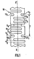
- FIG. 1 a spring 10 produced in a hollow cylindrical quartz tube in the case of a spring having a pitch with six recesses 11 1 to 11 6 .
- the recesses 11 1 and 11 7 are similar and are spaced apart by a pitch T.
- the width of each recess is h.
- FIGS. 2A to 2F represent a preferred method of carrying out the invention in the case of a step with three recesses for the simplification of the drawing.
- a multi-wire saw is used for this, comprising for example three wires 20 1 , 20 2 , 20 3 spaced apart from each other by T. The width of the wires is substantially h. Three cuts are made 22 1 , 22 2 , 22 3 , with the direction of penetration represented by the arrow 21. The cuts are made until the wires are flush with the internal wall 25, that is to say after having passed through the entire hollow area 26 of the cylindrical tube.
- the three wires are then moved along the longitudinal axis of the tube by a distance T / 3 and three new recesses are made 23 1 , 23 2 , 23 3 .
- the rotation and translation operations similar to the previous ones are carried out and then three other recesses are made.
- the pitch of rotation is 360 ° / n and the pitch of translation of each wire is T / n.
- FIGS. 3A to 3C represent a section, along the axis of symmetry of the tube, of a spring according to the invention but shown to facilitate drawing, in the case of a spring with a pitch with two recesses.
- This structure is very simplified but allows a better visualization of the forces used.
- the section according to FIG. 3A represents a part of the spring at rest.
- FIG. 3B By considering displacements being made with respect to a central turn centered on the axis YY ', one obtains according to FIG. 3B a spring in elongation and according to FIG. 3C a spring in compression. In these two cases, the directions of the forces used which are symmetrical with respect to the axis YY 'are observed on the central turn.
- the forces represented by arrows 31 and 33 in Figure 3B act in compression on the forces represented by arrows 32 and 34.
- the forces represented by arrows 35 and 37 act in extension with the forces represented by arrows 36 and 38.
- the composition of these forces reveals that a spring structure having sharp angles is worse than a structure with rounded angles. For this reason, the bottom of each recess, for example 39, should preferably have a rounded structure. This is easily obtained by cutting using a wire saw.
- each recess such as 50
- the external edges of each recess preferably have a rounded structure. This can be obtained by operating a local chemical pickling carried out after the recesses have been made.
- the section according to FIG. 3C represents the same spring under conditions of compression with other directions of the forces 41, 42, 43 and 44 used. Again the preferred structure is that with rounded corners 49 and 60.
- FIGS. 3A to 3C represent a deliberately simplified example.
- the same balance of forces mechanisms are present, but in a much more complex manner, in springs according to the invention, with a number of recesses greater than 2 per step.
- the elongation curve as a function of the force is substantially linear. Its slope is approximately 10- 2 m / N. It operates both in compression (zone 41) and in extension (zone 42). This spring can also withstand low torsional forces.
- the relationship between the width of the cut h and the distance e between two consecutive cut can be over a wide range of values depending on the respective dimensions of h and e.
- the choice on the value h can also be very wide. It is possible to use wires, provided with abrasives, several millimeters in diameter and to make large recesses allowing the production of large springs.
- the sawing technique adapts correctly to these extreme conditions and allows economical production of springs made of non-metallic refractory material.
- the springs of non-metallic refractory material which have just been described can be used in applications which require the transmission or absorption of forces of low amplitude under conditions of high temperature for example to compensate for the expansions of moving parts.
- Such a spring can be used at temperatures exceeding 1000 ° C when it is made of quartz, in graphite or boron nitride, retaining its basic elastic properties. It is thus possible to obtain a spring with a material in the amorphous state having qualities analogous to a metal spring but suitable for high temperatures.
Abstract
Ce ressort (10) est en matériau réfractaire tel que le quartz, le nitrure de bore, le graphite. il est constitué d'évidements (111 à 117) non jointifs de hauteur h répartis selon une disposition hélicoïdale. Le procédé de réalisation utilise une scie à fils pour effectuer ces évidements dans un tube cylindrique creux auquel on fait subir des rotations entre chaque opération de sciage. L'absence de microfractures confère à ce type de ressort une bonne élasticité jusqu'aux hautes températures. Il trouve son application dans la transmission de mouvement aux hautes températures en particulier lorsque des conditions de parfaite propreté sont désirées comme, par exemple, dans le cas de la métallurgie des semiconducteurs. Application: Métallurgie des semiconducteurs, mécanique des hautes températures.This spring (10) is made of refractory material such as quartz, boron nitride, graphite. it consists of non-contiguous recesses (111 to 117) of height h distributed in a helical arrangement. The production method uses a wire saw to make these recesses in a hollow cylindrical tube which is rotated between each sawing operation. The absence of microfractures gives this type of spring good elasticity up to high temperatures. It finds its application in the transmission of motion at high temperatures, in particular when conditions of perfect cleanliness are desired, such as, for example, in the metallurgy of semiconductors. Application: Semiconductor metallurgy, high temperature mechanics.
Description
L'invention concerne un procédé pour la réalisation d'un ressort de type cylindrique qui présente des évidements non jointifs de hauteur h, réalisés dans un tube cylindrique creux selon des bandes, distantes entre elles de e, sensiblement perpendiculaires à l'axe du tube cylindrique creux, ces évidements étant répartis dans le tube selon une disposition hélicoïdale, chaque évidement étant constitué par un cylindre de hauteur h, dont la génératrice se déplace parallèlement à l'axe du tube sur une courbe fermée formée d'une partie du contour d'une section sensiblement droite du tube cylindrique creux, comprenant une portion des contours relatifs aux faces interne et externe du tube cylindrique creux, la courbe fermée subissant, pour deux évidements voisins, une rotation par rapport à l'axe du tube cylindrique creux.The invention relates to a method for producing a cylindrical type spring which has non-contiguous recesses of height h, produced in a hollow cylindrical tube in strips, spaced from each other by e, substantially perpendicular to the axis of the tube. cylindrical hollow, these recesses being distributed in the tube in a helical arrangement, each recess being constituted by a cylinder of height h, the generatrix of which moves parallel to the axis of the tube on a closed curve formed by part of the contour d a substantially straight section of the hollow cylindrical tube, comprising a portion of the contours relating to the internal and external faces of the hollow cylindrical tube, the closed curve undergoing, for two neighboring recesses, a rotation relative to the axis of the hollow cylindrical tube.
Un ressort de ce type est connu du document FR 1 090 004 qui décrit un ressort hélicoïdal constitué par un barreau en un matériau élastique, percé axialement d'un trou longitudinal débouchant à l'une au moins des extrémités et dans lequel sont ménagées des entailles formant des fentes transversales qui débouchent dans ledit trou longitudinal, ces fentes étant décalées les unes par rapport aux autres, dans le sens longitudinal et périphérique, de manière à laisser subsister entre elles au moins une série de lames élastiques reliées entre elles en zigzag.A spring of this type is known from document FR 1 090 004 which describes a helical spring constituted by a rod made of an elastic material, axially pierced with a longitudinal hole opening at at least one of the ends and in which notches are formed. forming transverse slots which open into said longitudinal hole, these slots being offset with respect to each other, in the longitudinal and peripheral directions, so as to leave at least one series of elastic blades connected together in a zigzag manner.
Un tel ressort est prévu pour être traité thermiquement avant usinage, afin d'éviter les déformations dues au traitement et d'obtenir des dimensions très précises et la possibilité d'usiner les extrémités, le tout avec des bonnes caractéristiques de qualité du matériau élastique. Ce ressort peut être réalisé en acier, en bronze, en superpolyamide, en caoutchouc, en effectuant une opération de fraisage de ces matériaux.Such a spring is intended to be heat treated before machining, in order to avoid deformations due to the treatment and to obtain very precise dimensions and the possibility of machining the ends, all with good quality characteristics of the elastic material. This spring can be made of steel, bronze, superpolyamide, rubber, by performing a milling operation on these materials.
Or les températures de fonctionnement auxquelles peuvent opérer de tels ressorts sont nettement inférieures à 500°C et ceux-ci ne peuvent donc en aucun cas remplir la fonction de ressort aux hautes températures, par exemple atteindre des températures de fonctionnement supérieures à 1000°C.However, the operating temperatures at which such springs can operate are much lower than 500 ° C. and these can therefore in no case fulfill the function of spring at high temperatures, for example reaching operating temperatures above 1000 ° C.
D'autre part les applications qui nécessitent de disposer de ressorts opérant aux hautes températures sont par exemple la métallurgie des semiconducteurs. Or dans une telle application le problème de la pollution du milieu dans lequel opèrent les ressorts est de la plus grande importance et les matériaux prévus par le brevet FR 1 090 004 ne sont pas adaptés à cet usage. Un changement de matériau s'impose et le choix doit être opéré parmi les matériaux réfractaires tels que le quartz, le nitrure de bore, le graphite. Mais l'opération de fraisage utilisée dans ce document ne permet pas de réaliser un élément élastique qui puisse répondre à la fonction d'un ressort. En effet, ces opérations de fraisage génèrent des microfractures principalement dans les zones où l'élasticité du matériau est sollicitée et des cassures des éléments obtenus apparaissent rendant l'élément ainsi réalisé impropre à toute fonction de ressort à haute température.On the other hand, the applications which require the availability of springs operating at high temperatures are, for example, the metallurgy of semiconductors. However in such an application the problem of pollution of the environment in which the springs operate is of the greatest importance and the materials provided by patent FR 1 090 004 are not suitable for this use. A change of material is necessary and the choice must be made from refractory materials such as quartz, boron nitride, graphite. However, the milling operation used in this document does not make it possible to produce an elastic element which can fulfill the function of a spring. Indeed, these milling operations generate microfractures mainly in the areas where the elasticity of the material is stressed and breaks in the elements obtained appear making the element thus produced unsuitable for any spring function at high temperature.
Le but de l'invention est donc de proposer un procédé de réalisation d'un véritable ressort utilisable aux hautes températures.The object of the invention is therefore to propose a process for producing a true spring usable at high temperatures.
Pour cela l'invention telle définie dans le préambule est remarquable en ce que dans un tube cylindrique creux, en matériau réfractaire non métallique,
- - on effectue une opération de sciage partiel du tube, selon une direction correspondant à une section sensiblement droite du tube, à l'aide d'une scie à fils, ayant au moins un fil, afin de réaliser au moins un évidement partiel du tube, le sciage partiel étant arrêté après avoir traversé la totalité de la partie creuse du tube, la largeur du fil correspondant sensiblement à la largeur de l'évidement recherchée,
- - on déplace le tube par rapport au fil de la scie, selon une rotation par rapport à l'axe du tube d'un angle de 360°/n et une translation parallèlement à l'axe du tube, d'une distance T/n, où T représente la distance entre deux évidements consécutifs situés sur une même génératrice et n le nombre d'évidements à réaliser dans le tube sur la distance T,
- - on répète l'opération de sciage puis l'opération de déplacement jusqu'à l'obtention d'un ressort en matériau réfractaire non métallique ayant le nombre d'évidements et la longueur recherchés.
- - We perform a partial sawing operation of the tube, in a direction corresponding to a substantially straight section of the tube, using a wire saw, having at least one wire, in order to achieve at least a partial recess of the tube , the partial sawing being stopped after having traversed the entire hollow part of the tube, the width of the wire substantially corresponding to the width of the desired recess,
- - The tube is moved relative to the saw wire, according to a rotation relative to the axis of the tube by an angle of 360 ° / n and a translation parallel to the axis of the tube, by a distance T / n, where T represents the distance between two consecutive recesses located on the same generator and n the number of recesses to be made in the tube over the distance T,
- - The sawing operation is repeated and then the movement operation until a spring of non-metallic refractory material is obtained having the number of recesses and the desired length.
Le matériau réfractaire non métallique peut être du quartz, du graphite ou du nitrure de bore. Préférentiellement la section droite du tube cylindrique creux est annulaire. Le rapport h/e peut être sensiblement égal à 1.The non-metallic refractory material can be quartz, graphite or boron nitride. Preferably, the cross section of the hollow cylindrical tube is annular. The h / e ratio can be substantially equal to 1.
Dans la métallurgie des semiconducteurs il est très souvent nécessaire d'effectuer des opérations de mouvement à l'intérieur d'une enceinte fermée dans laquelle règne un certain nombre d'équilibres de pression, de température, de composition chimique. La transmission de mouvements ou de forces s'avère difficile, et ceci bien qu'ils soient généralement de faibles amplitudes.In semiconductor metallurgy it is very often necessary to carry out movement operations inside a closed enclosure in which a certain number of equilibria of pressure, temperature, chemical composition prevails. The transmission of movements or forces proves to be difficult, and this although they are generally of small amplitudes.
Pour traiter ce problème le ressort selon l'invention est réalisé préférentiellement dans un tube de quartz dont la section droite est annulaire. Les évidements sont ainsi réalisés selon une technique à froid qui n'apporte pas de perturbations telles que microfissures ou autres, la zone perturbée le long de la surface de découpe étant de très faible épaisseur. Ces évidements sont pratiqués sensiblement selon une section droite. Après avoir traversé la première face de la surface interne du tube cylindrique préférentiellement ils effleurent la seconde face.To deal with this problem, the spring according to the invention is preferably produced in a quartz tube whose cross section is annular. The recesses are thus produced according to a cold technique which does not bring disturbances such as microcracks or the like, the disturbed area along the cutting surface being very thin. These recesses are made substantially in a cross section. After having crossed the first face of the internal surface of the cylindrical tube, preferably they touch the second face.
Des évidements voisins sont placés à une distance e les uns des autres, décalés en rotation par rapport à l'axe du tube cylindrique, de sorte que tous les évidements réalisés dans le tube se succèdent selon une répartition hélicoïdale. Plusieurs évidements sont donc placés sur une même génératrice à une distance T tel que n = ![]()
![]()
Pour réaliser un tel ressort il est préférable d'utiliser une scie multifils dont les fils sont distants de T. On opère ainsi simultanément tous les évidements distants de T. Puis on tourne le tube de quartz sur son support d'un angle 360°/n et on effectue à nouveau tous les évidements distants de T. L'opération est effectuée pour les n rotations. On peut également utiliser un laser dans la mesure où la zone perturbée longeant le bord de découpe, n'est pas trop large eu égard à l'épaisseur e de la zone restante.To make such a spring, it is preferable to use a multi-wire saw whose wires are spaced from T. We thus operate all the recesses distant from T simultaneously. Then we turn the quartz tube on its support by a 360 ° angle / n and all the recesses distant from T are again performed. The operation is performed for the n rotations. It is also possible to use a laser insofar as the disturbed zone along the cutting edge is not too large having regard to the thickness e of the remaining zone.
L'invention sera mieux comprise, à l'aide des figures suivantes, données à titre d'exemples non limitatifs, qui représentent :
- la figure 1 : une portion de ressort selon l'invention,
- les figures 2A à 2F : une illustration du mécanisme de découpe d'un tube cylindrique creux et du ressort ainsi obtenu selon l'invention avec n = 3,
- les figures 3A à 3C : une représentation simplifiée, d'une coupe, selon l'axe de symétrie du tube, d'un ressort selon l'invention,
- la figure 4 : une courbe de compression-extension en fonction de la force appliquée.
- FIG. 1: a portion of spring according to the invention,
- FIGS. 2A to 2F: an illustration of the mechanism for cutting a hollow cylindrical tube and the spring thus obtained according to the invention with n = 3,
- FIGS. 3A to 3C: a simplified representation of a section, along the axis of symmetry of the tube, of a spring according to the invention,
- Figure 4: a compression-extension curve as a function of the force applied.
Sur la figure 1 est représenté un ressort 10 réalisé dans un tube cylindrique creux en quartz dans le cas d'un ressort ayant un pas à six évidements 111 à 116. Les évidements 111 et 117 sont analogues et sont distants d'un pas T. Les évidements sont espacés de e et décalés en rotation par rapport à l'axe XX' d'un angle de 360°/6 = 60° dans l'exemple représenté. La largeur de chaque évidement est h.In FIG. 1 is shown a
Les figures 2A à 2F représentent une méthode préférentielle de réalisation de l'invention dans le cas d'un pas à trois évidements pour la simplification du dessin. On utilise pour cela une scie multifils comprenant par exemple trois fils 201, 202, 203 distants entre eux de T. La largeur des fils est sensiblement de h. Trois découpes sont effectuées 221, 222, 223, avec le sens de pénétration représenté par la flèche 21. Les découpes sont réalisées jusqu'à ce que les fils affleurent la paroi interne 25, c'est-à-dire après avoir traversé la totalité de la zone creuse 26 du tube cylindrique.FIGS. 2A to 2F represent a preferred method of carrying out the invention in the case of a step with three recesses for the simplification of the drawing. A multi-wire saw is used for this, comprising for example three wires 20 1 , 20 2 , 20 3 spaced apart from each other by T. The width of the wires is substantially h. Three cuts are made 22 1 , 22 2 , 22 3 , with the direction of penetration represented by the
Afin d'obtenir un pas à trois évidements le tube est alors tourné par rapport à son axe d'un angle de 360°/3 = 120°, la position des lettres A, B, C mettant en relief cette rotation. Les trois fils sont alors déplacés selon l'axe longitudinal du tube d'une distance T/3 et trois nouveaux évidements sont réalisés 231, 232, 233. Les opérations de rotation et de translation analogues aux précédentes sont effectuées puis trois autres évidements sont réalisés.In order to obtain a step with three recesses, the tube is then rotated with respect to its axis by an angle of 360 ° / 3 = 120 °, the position of the letters A, B, C highlighting this rotation. The three wires are then moved along the longitudinal axis of the tube by a distance T / 3 and three new recesses are made 23 1 , 23 2 , 23 3 . The rotation and translation operations similar to the previous ones are carried out and then three other recesses are made.
Dans le cas le plus général pour un pas comprenant n évidements, le pas de rotation est de 360°/n et le pas de translation de chaque fils est de T/n.In the most general case for a pitch comprising n recesses, the pitch of rotation is 360 ° / n and the pitch of translation of each wire is T / n.
Les figures 3A à 3C représentent une coupe, selon l'axe de symétrie du tube, d'un ressort selon l'invention mais représenté pour faciliter le dessin, dans le cas d'un ressort avec un pas à deux évidements. Cette structure est très simplifiée mais permet de mieux visualiser les forces mises en oeuvre. La coupe selon la figure 3A représente une partie de ressort au repos. En considérant des déplacements se faisant par rapport à une spire centrale centrée sur l'axe YY', on obtient selon la figure 3B un ressort en élongation et selon la figure 3C un ressort en compression. Dans ces deux cas on observe sur la spire centrale les directions des forces mises en oeuvre qui sont symétriques par rapport à l'axe YY'. Les forces représentées par les flèches 31 et 33 dans la figure 3B agissent en compression sur les forces représentées par les flèches 32 et 34. Les forces représentées par les flèches 35 et 37 agissent en extension avec les forces représentées par les flèches 36 et 38. La composition de ces forces révèle qu' une structure de ressort ayant des angles vifs est moins bonne qu'une structure présentant des angles arrondis. Pour cette raison le fond de chaque évidement, par exemple 39, doit préférentiellement avoir une structure arrondie. Ceci est aisément obtenu par un découpage opéré à l'aide d'une scie à fils.FIGS. 3A to 3C represent a section, along the axis of symmetry of the tube, of a spring according to the invention but shown to facilitate drawing, in the case of a spring with a pitch with two recesses. This structure is very simplified but allows a better visualization of the forces used. The section according to FIG. 3A represents a part of the spring at rest. By considering displacements being made with respect to a central turn centered on the axis YY ', one obtains according to FIG. 3B a spring in elongation and according to FIG. 3C a spring in compression. In these two cases, the directions of the forces used which are symmetrical with respect to the axis YY 'are observed on the central turn. The forces represented by
Pour les mêmes raisons les bords externes de chaque évidement, tel que 50, ont préférentiellement une structure arrondie. Ceci peut être obtenu en opérant un décapage chimique local effectué après la réalisation des évidements.For the same reasons the external edges of each recess, such as 50, preferably have a rounded structure. This can be obtained by operating a local chemical pickling carried out after the recesses have been made.
La coupe selon la figure 3C représente le même ressort dans des conditions de compression avec d'autres directions des forces 41, 42, 43 et 44 mises en oeuvre. Là aussi la structure préférentielle est celle avec des angles 49 et 60 arrondis.The section according to FIG. 3C represents the same spring under conditions of compression with other directions of the
Les coupes des figures 3A à 3C représentent un exemple volontairement simplifié. Les mêmes mécanismes d'équilibre de forces se présentent, mais de manière bien plus complexe, dans des ressorts selon l'invention, avec un nombre d'évidements supérieur à 2 par pas.The sections in FIGS. 3A to 3C represent a deliberately simplified example. The same balance of forces mechanisms are present, but in a much more complex manner, in springs according to the invention, with a number of recesses greater than 2 per step.
La figure 4 fournit la courbe d'élongation en compression-extension en fonction de la force appliquée pour un ressort en quartz selon l'invention. Pour un ressort ayant les caractéristiques géométriques suivantes :
- . longueur : 20 mm
- . nombre d'évidements : 26
- . pas T = 2,25 mm
- . largeur de découpe h = 0,2 mm
- . distance entre découpe e = 0,548 mm
- . épaisseur de la paroi du tube : 1 mm
- . diamètre d = 18 mm.
- . length: 20 mm
- . number of recesses: 26
- . pitch T = 2.25 mm
- . cutting width h = 0.2 mm
- . distance between cut e = 0.548 mm
- . tube wall thickness: 1 mm
- . diameter d = 18 mm.
La courbe d'élongation en fonction de la force est sensiblement linéaire. Sa pente est environ de 10-2 m/N. Il opère aussi bien en compression (zone 41) qu'en extension (zone 42).Ce ressort peut également supporter de faibles forces de torsion.The elongation curve as a function of the force is substantially linear. Its slope is approximately 10- 2 m / N. It operates both in compression (zone 41) and in extension (zone 42). This spring can also withstand low torsional forces.
Le rapport entre la largeur de la découpe h et la distance e entre deux découpes consécutives peut se situer sur une large gamme de valeurs selon les dimensions respectives de h et e.The relationship between the width of the cut h and the distance e between two consecutive cut can be over a wide range of values depending on the respective dimensions of h and e.
Les situations extrêmes les plus caractéristiques sont pour les faibles et les fortes valeurs de h et e.The most characteristic extreme situations are for the low and high values of h and e.
Pour les valeurs faibles, il est possible de réaliser un ressort avec les valeurs h = e = 50 µm pour lequel le rapport h/e est sensiblement égal à 1. Le procédé de découpe n'apporte que très peu de perturbations telles que microfractures ou autres dans la zone de découpe, ce qui permet de conserver au matériau situé entre deux évidements, une qualité intrinsèque satisfaisante pour l'application visée. En effet, pour une faible épaisseur de matériau restant, des microfractures rendraient impossible la réalisation d'un ressort.For low values, it is possible to produce a spring with the values h = e = 50 μm for which the h / e ratio is substantially equal to 1. The cutting process brings very little disturbance such as microfractures or others in the cutting area, which allows the material located between two recesses to maintain an intrinsic quality satisfactory for the intended application. Indeed, for a small thickness of remaining material, microfractures would make it impossible to produce a spring.
Pour les valeurs élevées, la distance e n'ayant pas de limite particulière, le choix sur la valeur h peut également être très étendu. Il est possible d'utiliser des fils, munis d'abrasifs, de plusieurs millimètres de diamètre et de faire des évidements larges autorisant la réalisation de ressorts de grandes dimensions. La technique du sciage s'adapte correctement à ces conditions extrêmes et permet une réalisation économique de ressorts en matériau réfractaire non métallique.For high values, the distance e having no particular limit, the choice on the value h can also be very wide. It is possible to use wires, provided with abrasives, several millimeters in diameter and to make large recesses allowing the production of large springs. The sawing technique adapts correctly to these extreme conditions and allows economical production of springs made of non-metallic refractory material.
Les ressorts en matériau réfractaire non métallique qui viennent d'être décrits peuvent être utilisés dans les applications qui nécessitent la transmission ou l'absorption de forces de faible amplitude dans des conditions de température élevée par exemple pour compenser les dilatations de pièces mobiles. Un tel ressort peut être utilisé à des températures dépassant 1000°C lorsqu'il est réalisé en quartz, en graphite ou en nitrure de bore, en conservant ses propriétés élastiques de base. Il est ainsi possible d'obtenir un ressort avec un matériau à l'état amorphe disposant de qualités analogues à un ressort métallique mais adapté aux hautes températures.The springs of non-metallic refractory material which have just been described can be used in applications which require the transmission or absorption of forces of low amplitude under conditions of high temperature for example to compensate for the expansions of moving parts. Such a spring can be used at temperatures exceeding 1000 ° C when it is made of quartz, in graphite or boron nitride, retaining its basic elastic properties. It is thus possible to obtain a spring with a material in the amorphous state having qualities analogous to a metal spring but suitable for high temperatures.
Dans ces situations de haute température il possède en outre l'intérêt de ne pratiquement pas fournir de vapeurs par évaporation de son matériau constitutif, ce qui permet de l'utiliser dans des atmosphères nécessitant de bonnes conditions de propreté.In these high temperature situations it also has the advantage of practically not providing vapors by evaporation of its constituent material, which allows it to be used in atmospheres requiring good conditions of cleanliness.
Il peut donc être utilisé dans la mécanique des hautes températures, la métallurgie des semiconducteurs, la transmission de mouvements sous vide à haute température...It can therefore be used in high temperature mechanics, semiconductor metallurgy, transmission of vacuum movements at high temperature ...
Claims (8)
Applications Claiming Priority (2)
| Application Number | Priority Date | Filing Date | Title |
|---|---|---|---|
| FR8515653 | 1985-10-22 | ||
| FR8515653A FR2588928B1 (en) | 1985-10-22 | 1985-10-22 | CYLINDRICAL-TYPE SPRING FOR USE AT HIGH TEMPERATURES AND PROCESS FOR PRODUCING SUCH A SPRING |
Publications (2)
| Publication Number | Publication Date |
|---|---|
| EP0220769A1 true EP0220769A1 (en) | 1987-05-06 |
| EP0220769B1 EP0220769B1 (en) | 1989-01-04 |
Family
ID=9324080
Family Applications (1)
| Application Number | Title | Priority Date | Filing Date |
|---|---|---|---|
| EP86201815A Expired EP0220769B1 (en) | 1985-10-22 | 1986-10-20 | Process for the manufacture of a cylindrical type high-temperature spring |
Country Status (5)
| Country | Link |
|---|---|
| US (1) | US4826143A (en) |
| EP (1) | EP0220769B1 (en) |
| JP (1) | JPS62101929A (en) |
| DE (1) | DE3661647D1 (en) |
| FR (1) | FR2588928B1 (en) |
Cited By (2)
| Publication number | Priority date | Publication date | Assignee | Title |
|---|---|---|---|---|
| EP0398046A2 (en) * | 1989-05-15 | 1990-11-22 | Zircoa, Inc. | Process for making a flexible ceramic element and flexible ceramic element obtained thereby |
| EP3339676A4 (en) * | 2015-07-16 | 2019-06-26 | Hyung Woo Kim | Spring structure having multiple coil-shaped unit springs and method for manufacturing same |
Families Citing this family (8)
| Publication number | Priority date | Publication date | Assignee | Title |
|---|---|---|---|---|
| US5062619A (en) * | 1989-04-03 | 1991-11-05 | Nabeya Kogyo Co., Ltd. | Non-linear spring |
| US6034532A (en) * | 1993-07-01 | 2000-03-07 | Alphatest Corporation | Resilient connector having a tubular spring |
| US5982187A (en) * | 1993-07-01 | 1999-11-09 | Alphatest Corporation | Resilient connector having a tubular spring |
| FR2772748B1 (en) * | 1997-12-22 | 2000-03-17 | Snecma | METHOD FOR MANUFACTURING A SPRING OF A THERMOSTRUCTURAL COMPOSITE MATERIAL |
| JP2001221269A (en) * | 2000-02-07 | 2001-08-17 | Super Silicon Kenkyusho:Kk | Quarts coil spring and its manufacturing method |
| DE10149746C1 (en) * | 2001-10-09 | 2003-05-28 | Siemens Ag | Process for producing a tube spring and actuator unit with such a tube spring |
| TWI399354B (en) | 2007-06-07 | 2013-06-21 | Ibiden Co Ltd | Graphite material and a method of producing graphite material |
| CN102312949A (en) * | 2011-10-13 | 2012-01-11 | 浙江大学台州研究院 | Manufacturing method of spiral spring used for elastic hinge of glasses |
Citations (10)
| Publication number | Priority date | Publication date | Assignee | Title |
|---|---|---|---|---|
| US1557958A (en) * | 1924-08-26 | 1925-10-20 | American Mach & Foundry | Flexible coupling |
| FR1090004A (en) * | 1953-07-22 | 1955-03-25 | Spring | |
| US2888258A (en) * | 1956-05-11 | 1959-05-26 | Hoffstrom Bo Nilsson | Springs |
| DE1912363A1 (en) * | 1968-03-20 | 1969-10-09 | United Aircraft Corp | Spring element |
| US3720740A (en) * | 1970-06-24 | 1973-03-13 | Hitachi Ltd | Low pressure sintering of boron nitride using low thermal expansion static sintering molds |
| FR2330510A1 (en) * | 1975-11-07 | 1977-06-03 | Sotarem Sa | Cutting machine with parallel mounted drums - has helical groove running length of drums with abrasive metal strip wound to form continuous sheet |
| FR2404770A2 (en) * | 1975-03-06 | 1979-04-27 | Pean Pierre | Tubular elastic spring element - has staggered sets of circumferential slots to form array of blade-like elements |
| EP0039491A1 (en) * | 1980-05-05 | 1981-11-11 | Alfred Robertson Austen | A resettable apparatus for producing time-delayed force and/or displacement response |
| EP0052523A1 (en) * | 1980-11-18 | 1982-05-26 | Maxon Corporation | Gate valve |
| US4412675A (en) * | 1981-05-11 | 1983-11-01 | Mitsubishi Pencil Co., Ltd. | Carbon spring and process for preparing the same |
Family Cites Families (13)
| Publication number | Priority date | Publication date | Assignee | Title |
|---|---|---|---|---|
| CA761814A (en) * | 1967-06-27 | Remoleur Jacques | Fall-damping device | |
| BE353934A (en) * | 1927-09-16 | |||
| FR938493A (en) * | 1944-05-17 | 1948-09-16 | Linde Air Prod Co | Process for hot forming a single crystal body of corundum or spinel, and single crystal body obtained by this process |
| FR57458E (en) * | 1947-07-19 | 1953-01-28 | Linde Air Prod Co | Process for hot forming a single crystal body of corundum or spinel, and single crystal body obtained by this process |
| US2854230A (en) * | 1955-10-31 | 1958-09-30 | Vibradamp Corp | Glass fiber spring unit and method of making same |
| US2852424A (en) * | 1957-04-30 | 1958-09-16 | Frank W Reinhart | Reinforced plastic springs |
| AU7709975A (en) * | 1974-01-16 | 1976-07-08 | Saturnini E | Cage-like spring |
| US4092972A (en) * | 1977-02-11 | 1978-06-06 | Crystal Systems, Inc. | Process of cutting wafers |
| DE3117567C2 (en) * | 1980-05-02 | 1983-05-11 | Fukuvi Chemical Industry Co., Ltd., Fukui | Process for the preparation of malleable, flexible graphite grains, and their use for the production of graphite shaped bodies |
| JPS5722436A (en) * | 1980-07-16 | 1982-02-05 | Nhk Spring Co Ltd | Vibration damper |
| DE3216200A1 (en) * | 1982-04-30 | 1983-11-03 | Wacker-Chemitronic Gesellschaft für Elektronik-Grundstoffe mbH, 8263 Burghausen | METHOD FOR SAWING CRYSTAL RODS AND MULTI-BLADE INTERNAL HOLE SAW FOR CARRYING OUT THE METHOD |
| US4669172A (en) * | 1983-02-07 | 1987-06-02 | Circon Corporation | Method for fabrication of flexible shaft |
| US4650619A (en) * | 1983-12-29 | 1987-03-17 | Toshiba Ceramics Co., Ltd. | Method of machining a ceramic member |
-
1985
- 1985-10-22 FR FR8515653A patent/FR2588928B1/en not_active Expired
-
1986
- 1986-10-20 JP JP61247659A patent/JPS62101929A/en active Pending
- 1986-10-20 DE DE8686201815T patent/DE3661647D1/en not_active Expired
- 1986-10-20 EP EP86201815A patent/EP0220769B1/en not_active Expired
-
1988
- 1988-08-12 US US07/232,550 patent/US4826143A/en not_active Expired - Fee Related
Patent Citations (10)
| Publication number | Priority date | Publication date | Assignee | Title |
|---|---|---|---|---|
| US1557958A (en) * | 1924-08-26 | 1925-10-20 | American Mach & Foundry | Flexible coupling |
| FR1090004A (en) * | 1953-07-22 | 1955-03-25 | Spring | |
| US2888258A (en) * | 1956-05-11 | 1959-05-26 | Hoffstrom Bo Nilsson | Springs |
| DE1912363A1 (en) * | 1968-03-20 | 1969-10-09 | United Aircraft Corp | Spring element |
| US3720740A (en) * | 1970-06-24 | 1973-03-13 | Hitachi Ltd | Low pressure sintering of boron nitride using low thermal expansion static sintering molds |
| FR2404770A2 (en) * | 1975-03-06 | 1979-04-27 | Pean Pierre | Tubular elastic spring element - has staggered sets of circumferential slots to form array of blade-like elements |
| FR2330510A1 (en) * | 1975-11-07 | 1977-06-03 | Sotarem Sa | Cutting machine with parallel mounted drums - has helical groove running length of drums with abrasive metal strip wound to form continuous sheet |
| EP0039491A1 (en) * | 1980-05-05 | 1981-11-11 | Alfred Robertson Austen | A resettable apparatus for producing time-delayed force and/or displacement response |
| EP0052523A1 (en) * | 1980-11-18 | 1982-05-26 | Maxon Corporation | Gate valve |
| US4412675A (en) * | 1981-05-11 | 1983-11-01 | Mitsubishi Pencil Co., Ltd. | Carbon spring and process for preparing the same |
Cited By (3)
| Publication number | Priority date | Publication date | Assignee | Title |
|---|---|---|---|---|
| EP0398046A2 (en) * | 1989-05-15 | 1990-11-22 | Zircoa, Inc. | Process for making a flexible ceramic element and flexible ceramic element obtained thereby |
| EP0398046A3 (en) * | 1989-05-15 | 1991-12-11 | Zircoa, Inc. | Process for making a flexible ceramic element and flexible ceramic element obtained thereby |
| EP3339676A4 (en) * | 2015-07-16 | 2019-06-26 | Hyung Woo Kim | Spring structure having multiple coil-shaped unit springs and method for manufacturing same |
Also Published As
| Publication number | Publication date |
|---|---|
| FR2588928B1 (en) | 1989-09-01 |
| JPS62101929A (en) | 1987-05-12 |
| DE3661647D1 (en) | 1989-02-09 |
| EP0220769B1 (en) | 1989-01-04 |
| US4826143A (en) | 1989-05-02 |
| FR2588928A1 (en) | 1987-04-24 |
Similar Documents
| Publication | Publication Date | Title |
|---|---|---|
| EP0220769B1 (en) | Process for the manufacture of a cylindrical type high-temperature spring | |
| EP0148088B1 (en) | Flexible metallic gasket comprising vanishing protuberances | |
| FR2495508A1 (en) | PROCESS FOR MANUFACTURING PULLEYS BY ROLLING FROM A METAL SHEET AND PULLEYS THUS OBTAINED | |
| FR2706077A1 (en) | Glass polyhedra and method of manufacture | |
| WO2013135895A1 (en) | Sawing wire, method and equipment for manufacturing such a wire, and use | |
| EP0707941B1 (en) | Method and apparatus for making composite pipes with high mechanical and tribologic characteristics, and pipes obtained by said process | |
| FR2633213A1 (en) | Method of producing a fibrous preform for the manufacture of components made of composite material having a complex shape | |
| FR2866782A1 (en) | NOISE-REDUCING CUTTING FILAMENT FOR PLANT CUTTING APPARATUS | |
| FR2821905A1 (en) | CYLINDRICAL ROLLER BEARING IN NITRURATION STEEL | |
| EP0177418B1 (en) | Device for cutting cardboard tubes having a hard surface | |
| EP0618036A1 (en) | Process and apparatus for machining with laser beam | |
| FR2529504A1 (en) | Tool and method for the accurate cutting of cylindrical parts made in porous or alveolate elastic materials. | |
| EP1198840A1 (en) | Method for making a device comprising layers of planes of quantum dots | |
| EP0988950A1 (en) | Method of sawing stone, diamond cutting segment and saw blade equipped with such segment | |
| EP0227125B1 (en) | Vessel for the liquid-phase epitaxy of semiconductor films | |
| EP1351791B1 (en) | Method for making a flexible cutting tool, and resulting cutting tool | |
| WO2019058066A1 (en) | Method and device for cutting a mat or a panel of mineral wool or a board or a panel of porous construction material | |
| FR2637827A1 (en) | SYSTEM FOR CUTTING SOLID BODIES OF THE "A CABLE" TYPE | |
| EP0661136B1 (en) | Method for honing the surface of a workpiece and honing tool for carring out said method | |
| BE1011046A6 (en) | Drainage and/or gas capture tubes | |
| CH688854A5 (en) | Wire saw | |
| EP1447152A1 (en) | Device for forming in ogive like form, for spinning or fluopiercing of pieces of a round or ovoid section | |
| FR2589374A1 (en) | PROCESS FOR MAKING THREADS AND TOOL FOR IMPLEMENTING THIS PROCESS | |
| EP3010675A1 (en) | Set of plates or parts obtained by cutting a block of metal or composite material | |
| WO2023144254A1 (en) | Method for obtaining a substrate provided with a coating comprising a discontinuous thin metal layer |
Legal Events
| Date | Code | Title | Description |
|---|---|---|---|
| PUAI | Public reference made under article 153(3) epc to a published international application that has entered the european phase |
Free format text: ORIGINAL CODE: 0009012 |
|
| AK | Designated contracting states |
Kind code of ref document: A1 Designated state(s): DE FR GB IT NL |
|
| 17P | Request for examination filed |
Effective date: 19870720 |
|
| 17Q | First examination report despatched |
Effective date: 19880314 |
|
| GRAA | (expected) grant |
Free format text: ORIGINAL CODE: 0009210 |
|
| AK | Designated contracting states |
Kind code of ref document: B1 Designated state(s): DE FR GB IT NL |
|
| REF | Corresponds to: |
Ref document number: 3661647 Country of ref document: DE Date of ref document: 19890209 |
|
| ITF | It: translation for a ep patent filed |
Owner name: ING. C. GREGORJ S.P.A. |
|
| GBT | Gb: translation of ep patent filed (gb section 77(6)(a)/1977) | ||
| PGFP | Annual fee paid to national office [announced via postgrant information from national office to epo] |
Ref country code: NL Payment date: 19891031 Year of fee payment: 4 |
|
| PLBE | No opposition filed within time limit |
Free format text: ORIGINAL CODE: 0009261 |
|
| STAA | Information on the status of an ep patent application or granted ep patent |
Free format text: STATUS: NO OPPOSITION FILED WITHIN TIME LIMIT |
|
| 26N | No opposition filed | ||
| REG | Reference to a national code |
Ref country code: FR Ref legal event code: CD |
|
| PGFP | Annual fee paid to national office [announced via postgrant information from national office to epo] |
Ref country code: GB Payment date: 19901001 Year of fee payment: 5 |
|
| PGFP | Annual fee paid to national office [announced via postgrant information from national office to epo] |
Ref country code: FR Payment date: 19901023 Year of fee payment: 5 |
|
| ITTA | It: last paid annual fee | ||
| PGFP | Annual fee paid to national office [announced via postgrant information from national office to epo] |
Ref country code: DE Payment date: 19901218 Year of fee payment: 5 |
|
| PG25 | Lapsed in a contracting state [announced via postgrant information from national office to epo] |
Ref country code: NL Effective date: 19910501 |
|
| NLV4 | Nl: lapsed or anulled due to non-payment of the annual fee | ||
| PG25 | Lapsed in a contracting state [announced via postgrant information from national office to epo] |
Ref country code: GB Effective date: 19911020 |
|
| GBPC | Gb: european patent ceased through non-payment of renewal fee | ||
| PG25 | Lapsed in a contracting state [announced via postgrant information from national office to epo] |
Ref country code: FR Effective date: 19920630 |
|
| PG25 | Lapsed in a contracting state [announced via postgrant information from national office to epo] |
Ref country code: DE Effective date: 19920701 |
|
| REG | Reference to a national code |
Ref country code: FR Ref legal event code: ST |
|
| PG25 | Lapsed in a contracting state [announced via postgrant information from national office to epo] |
Ref country code: IT Free format text: LAPSE BECAUSE OF NON-PAYMENT OF DUE FEES;WARNING: LAPSES OF ITALIAN PATENTS WITH EFFECTIVE DATE BEFORE 2007 MAY HAVE OCCURRED AT ANY TIME BEFORE 2007. THE CORRECT EFFECTIVE DATE MAY BE DIFFERENT FROM THE ONE RECORDED. Effective date: 20051020 |