EP0220639B1 - Mit einer Hand bedienbare, hydraulisch angetriebene Biegevorrichtung - Google Patents
Mit einer Hand bedienbare, hydraulisch angetriebene Biegevorrichtung Download PDFInfo
- Publication number
- EP0220639B1 EP0220639B1 EP86114499A EP86114499A EP0220639B1 EP 0220639 B1 EP0220639 B1 EP 0220639B1 EP 86114499 A EP86114499 A EP 86114499A EP 86114499 A EP86114499 A EP 86114499A EP 0220639 B1 EP0220639 B1 EP 0220639B1
- Authority
- EP
- European Patent Office
- Prior art keywords
- reservoir
- matrix
- handle
- pump
- oil
- Prior art date
- Legal status (The legal status is an assumption and is not a legal conclusion. Google has not performed a legal analysis and makes no representation as to the accuracy of the status listed.)
- Expired - Lifetime
Links
- 238000005452 bending Methods 0.000 title claims abstract description 9
- 230000005540 biological transmission Effects 0.000 title claims abstract description 4
- 239000012530 fluid Substances 0.000 claims abstract description 7
- 239000012528 membrane Substances 0.000 claims description 8
- 238000010276 construction Methods 0.000 claims description 3
- 238000007789 sealing Methods 0.000 description 3
- 238000005086 pumping Methods 0.000 description 2
- 229910000831 Steel Inorganic materials 0.000 description 1
- 238000004873 anchoring Methods 0.000 description 1
- 238000013459 approach Methods 0.000 description 1
- 230000006835 compression Effects 0.000 description 1
- 238000007906 compression Methods 0.000 description 1
- 230000007547 defect Effects 0.000 description 1
- 230000002950 deficient Effects 0.000 description 1
- 230000000694 effects Effects 0.000 description 1
- 238000009434 installation Methods 0.000 description 1
- 238000012423 maintenance Methods 0.000 description 1
- 238000004519 manufacturing process Methods 0.000 description 1
- 239000000463 material Substances 0.000 description 1
- 230000009347 mechanical transmission Effects 0.000 description 1
- 230000035515 penetration Effects 0.000 description 1
- 239000004033 plastic Substances 0.000 description 1
- 229920003023 plastic Polymers 0.000 description 1
- 239000010959 steel Substances 0.000 description 1
Images
Classifications
-
- B—PERFORMING OPERATIONS; TRANSPORTING
- B25—HAND TOOLS; PORTABLE POWER-DRIVEN TOOLS; MANIPULATORS
- B25B—TOOLS OR BENCH DEVICES NOT OTHERWISE PROVIDED FOR, FOR FASTENING, CONNECTING, DISENGAGING OR HOLDING
- B25B7/00—Pliers; Other hand-held gripping tools with jaws on pivoted limbs; Details applicable generally to pivoted-limb hand tools
- B25B7/12—Pliers; Other hand-held gripping tools with jaws on pivoted limbs; Details applicable generally to pivoted-limb hand tools involving special transmission means between the handles and the jaws, e.g. toggle levers, gears
- B25B7/126—Pliers; Other hand-held gripping tools with jaws on pivoted limbs; Details applicable generally to pivoted-limb hand tools involving special transmission means between the handles and the jaws, e.g. toggle levers, gears with fluid drive
-
- B—PERFORMING OPERATIONS; TRANSPORTING
- B21—MECHANICAL METAL-WORKING WITHOUT ESSENTIALLY REMOVING MATERIAL; PUNCHING METAL
- B21D—WORKING OR PROCESSING OF SHEET METAL OR METAL TUBES, RODS OR PROFILES WITHOUT ESSENTIALLY REMOVING MATERIAL; PUNCHING METAL
- B21D7/00—Bending rods, profiles, or tubes
- B21D7/06—Bending rods, profiles, or tubes in press brakes or between rams and anvils or abutments; Pliers with forming dies
- B21D7/063—Pliers with forming dies
Definitions
- Tube bending devices are known as well that have more moderate dimensions, can be operated with a single hand, which are used in special cases, as it is common knowledge among the users, for example to bend tubes on place during their installation.
- Both the anchorable-type devices and the portable-type devices that can be operated with a single hand can, generally speaking, be of two kinds, that is those driven by a mechanical transmission and those having a hydraulic tramsmission.
- the present invention refers to the tube bending devices that can be operated with a single hand and having a hydraulic transmission.
- the known devices are heavy and require a considerable physical strength for their operation, the almost continuous use of same thus becoming very fatiguing; they are cumbersome, thereby making their use difficult and sometimes even impossible; they are not easily grasped and their training causes problems, especially in particular rooms and conditions, as is common knowledge among the specific operators, and, last but not least, to realize them a complicated manufacture is required, which is therefore expensive both from the point of view of building and from the point of view of maintenance.
- the dimensions being equal, they do not permit to bend tubes having a certain resistance, like rubber-lined steel tubes.
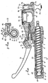
- reference numeral 1 denotes a matrix-die holding bar; 2 a return item, like a spring; 3 the inner head of bar 1, which is provided with a sealing gasket 4 and can slide within cylinder 5.
- reference numeral 6 denotes the outer body of the handle 7, which comprises a tubular item concentrical with 5 and having its two ends firmly connected with sleeve 8 and body 9 of the device, which body is manufactured as a unit construction with the remaining lower par, which is generally denoted by 10.
- Reference numeral 11 denotes a cavity obtained in the lower part of the body 10 and forming an oil reservoir; 12 denotes an elastic bellows type membrane, for example a rubber membrane or a membrane made of plastics or other suitable material, which is sealingly locked in its position by means of the rigid washer 13.
- 12 denotes an elastic bellows type membrane, for example a rubber membrane or a membrane made of plastics or other suitable material, which is sealingly locked in its position by means of the rigid washer 13.
- Reference numeral 14 denotes the support, also obtained in the lower part of reference 10, of item 15 which holds the counterdies 16, said support being provided with a hole 17, a perpendicular hole, in which the cylindrical shank 18 of item 15 is nested, said shank being provided with stop 19, like a movable ball inserted with a spring, which prevents the shank 18 from being unintentionally removed, and consequently item 15, which item 15 remains therefore in place, its rotation being moreover prevented by shoulder 20 and respective counter shoulder.
- Reference numeral 21 denotes a gap between items 5 and 6 which is provided to let the fluid (oil) flow in both directions, that is in the working stroke of the device, when bar 1 is moved forward, and in the release stroke, when the oil flows back thus allowing the withdrawal of bar 1 under the action of spring 2 after the work has been completed.
- Reference numeral 22 denotes a check valve, for example of the ball type, that allows oil to flow from reservoir 11 to chamber 23 whilst 24 denotes a second check valve, which also consists in a ball that is pressed against a sealing seat by a spring and allows oil to flow from said chamber 23 to the gap chamber 21.
- Said gap 21 is hydraulically connected with valve chamber of valve 24 and, by means of passage ways 40, with the chamber 43, said passage ways 40 being made in lengthwise direction within the blind-bottom sleeve 8 in correspondence with the threaded part of cylinder 5 on which the sleeve is screwed.
- Reference numeral 25 denotes a plunger that can freely slide axially within a cylindrical guiding bush 26 which has on its end facing chamber 23, an annular gasket 27 that seals plunger 25.
- a dolly spring 29 is engaged which is compression-loaded to allow afterwards the return, said spring finding reaction on an abutment formed at the end of chamber 23.
- Reference numeral 30 denotes a ball that is interposed between the head of the plunger 25 and the lever arm 31, said lever arm having its fulcrum on pivot 32.
- Reference numeral 33 denotes a stopping screw that is threaded on the body of lever 31 and abuts on the pump body 10 with its head, said spring being provided for the purpose of presetting the useful stroke of the lever 31.
- Reference numeral 34 denotes a vent hole and 35 denotes a pipe to the oil reservoir 11, through said pipe 35 said oil being discharged on back-flow.
- Said passage orifice 36 is closed by a cock 37 that comprises an outer handwheel 38, which can be operated by hand, with threaded rod 39 the smaller head of which sealingly presses ball 41 against the corresponding orifice of conduit 36 by sliding coaxially with same when the handwheel 38 is turned and lets on the contrary the orifice of passage way 36 free when the handwheel 38 is turned in the opposite direction.
- a cock 37 that comprises an outer handwheel 38, which can be operated by hand, with threaded rod 39 the smaller head of which sealingly presses ball 41 against the corresponding orifice of conduit 36 by sliding coaxially with same when the handwheel 38 is turned and lets on the contrary the orifice of passage way 36 free when the handwheel 38 is turned in the opposite direction.
- the working mode is as follows.
- the device is grasped with a single hand holding it on the cylindrical body 7 and the lever 31.
- plunger 25, onto which acts the annular sealing gasket 27, is pushed and slides within the cylinder 23, and said chamber being filled with oil the penetration of said plunger inside said chamber causes the delivery valve to be opened and a quantity of oil equal to the volume of the part of the plunger that has penetrated into the cylinder to pass in gap 21.
- Chamber 23 is then filled with new oil, thereby restoring the original conditions for a new pumping cycle.
- Every pumping cycle causes then the bar 1 to move forward on which there is installed a matrix-die the dimensions of which are suitable for the tube to be bent; thus the matrix-die approaches step by step the corresponding counter-dies 16 and causes the interposed tube to be progressively bent.
- the invention attains all the intended objects and allows moreover, the total length being equal, to realize larger radius bendings because the working stroke that the matrix-die holding bar 1 permits is much longer; such an advantage is rather remarkable too because it permits to attain in a substantial way larger radii than can be attained by means of the presently known tube bending devices of the type under discussion.
Landscapes
- Engineering & Computer Science (AREA)
- Mechanical Engineering (AREA)
- Bending Of Plates, Rods, And Pipes (AREA)
- Arrangement Or Mounting Of Control Devices For Change-Speed Gearing (AREA)
- Tubes (AREA)
- Shaping Of Tube Ends By Bending Or Straightening (AREA)
Claims (4)
Priority Applications (1)
| Application Number | Priority Date | Filing Date | Title |
|---|---|---|---|
| AT86114499T ATE54585T1 (de) | 1985-10-31 | 1986-10-20 | Mit einer hand bedienbare, hydraulisch angetriebene biegevorrichtung. |
Applications Claiming Priority (2)
| Application Number | Priority Date | Filing Date | Title |
|---|---|---|---|
| IT3492785U | 1985-10-31 | ||
| IT8534927U IT207711Z2 (it) | 1985-10-31 | 1985-10-31 | Apparecchio curvatubi a trasmissione idraulica azionabile con una sola mano |
Publications (3)
| Publication Number | Publication Date |
|---|---|
| EP0220639A2 EP0220639A2 (de) | 1987-05-06 |
| EP0220639A3 EP0220639A3 (en) | 1988-09-07 |
| EP0220639B1 true EP0220639B1 (de) | 1990-07-18 |
Family
ID=11240966
Family Applications (1)
| Application Number | Title | Priority Date | Filing Date |
|---|---|---|---|
| EP86114499A Expired - Lifetime EP0220639B1 (de) | 1985-10-31 | 1986-10-20 | Mit einer Hand bedienbare, hydraulisch angetriebene Biegevorrichtung |
Country Status (5)
| Country | Link |
|---|---|
| EP (1) | EP0220639B1 (de) |
| AT (1) | ATE54585T1 (de) |
| DE (1) | DE3672747D1 (de) |
| ES (1) | ES2016792B3 (de) |
| IT (1) | IT207711Z2 (de) |
Families Citing this family (2)
| Publication number | Priority date | Publication date | Assignee | Title |
|---|---|---|---|---|
| IT230365Y1 (it) * | 1993-07-16 | 1999-06-02 | Imb Srl | Utensile per punzonare |
| IT237303Y1 (it) * | 1995-11-23 | 2000-09-05 | Cbc Spa | Apparecchio curvatubi a trasmissione idraulica |
Family Cites Families (9)
| Publication number | Priority date | Publication date | Assignee | Title |
|---|---|---|---|---|
| FR1164123A (fr) * | 1957-01-11 | 1958-10-06 | Pince hydraulique à main | |
| GB882614A (en) * | 1959-02-25 | 1961-11-15 | Mekler Dan | Improvements in or relating to hydraulic tools, adapted to be held and operated with one hand |
| FR2100998B1 (fr) * | 1970-08-04 | 1973-04-27 | Breton Leslie Le | Outil pour cintrage de tubes |
| CH610232A5 (de) * | 1975-01-27 | 1979-04-12 | Erich K Schmitter | |
| CH597985A5 (en) * | 1975-03-06 | 1978-04-28 | Willy Fluckiger | Pneumatic pincers for crimping eyelet onto cable |
| US4149381A (en) * | 1977-07-13 | 1979-04-17 | Dan Mekler | Single hand operated tool |
| IT1156153B (it) * | 1978-04-06 | 1987-01-28 | Liri Costruzioni Mecc | Perfezionamento in un apparecchio curvatubi idraulico portatile a comando manuale provvisto di testa girevole ed elementi curvanti reversibili per invertire la direzione del la curvatura del tubo |
| FR2466115A1 (fr) * | 1979-09-24 | 1981-03-27 | Sicame Sa | Pince a main pour le sertissage de connexions electriques |
| JPS585156B2 (ja) * | 1980-03-24 | 1983-01-29 | 株式会社 大洋発條製作所 | スナツプリング用の油圧式プライヤ− |
-
1985
- 1985-10-31 IT IT8534927U patent/IT207711Z2/it active
-
1986
- 1986-10-20 ES ES86114499T patent/ES2016792B3/es not_active Expired - Lifetime
- 1986-10-20 EP EP86114499A patent/EP0220639B1/de not_active Expired - Lifetime
- 1986-10-20 DE DE8686114499T patent/DE3672747D1/de not_active Expired - Lifetime
- 1986-10-20 AT AT86114499T patent/ATE54585T1/de not_active IP Right Cessation
Also Published As
| Publication number | Publication date |
|---|---|
| EP0220639A2 (de) | 1987-05-06 |
| IT8534927V0 (it) | 1985-10-31 |
| EP0220639A3 (en) | 1988-09-07 |
| IT207711Z2 (it) | 1988-02-08 |
| ATE54585T1 (de) | 1990-08-15 |
| DE3672747D1 (de) | 1990-08-23 |
| ES2016792B3 (es) | 1990-12-01 |
Similar Documents
| Publication | Publication Date | Title |
|---|---|---|
| US4263801A (en) | Hydraulic riveter | |
| EP1347845A1 (de) | Hydraulisch angetriebenes aufweithandwerkzeug | |
| TWM567695U (zh) | 液壓工具及迴路 | |
| EP1769853B1 (de) | Pneumatisches Ausgabesystem mit linearer Betätigung und Methode | |
| US4959899A (en) | Tube pulling device | |
| CA2102762A1 (en) | Two-stage pressure cylinder | |
| US2116004A (en) | Lubricating device | |
| EP0220639B1 (de) | Mit einer Hand bedienbare, hydraulisch angetriebene Biegevorrichtung | |
| JP6557790B2 (ja) | プレスフィッティング用のプレスデバイスを駆動する機械力を伝達するためのデバイスおよび方法 | |
| US3712516A (en) | Mechanism for ejecting plastic materials | |
| US8240520B2 (en) | Material extruder | |
| US4028473A (en) | Hydraulic powered lubricator and sprayer | |
| US20180161845A1 (en) | Hydraulic tool | |
| EP3386644B1 (de) | System und verfahren zur verringerung von lufteindringung in dichtungsrohre | |
| US8074733B2 (en) | Three-stage valve switch structure | |
| US4236549A (en) | Bleeder kit for bleeding a master cylinder | |
| EP0908657B1 (de) | Rohrschmiedegerät mit hydraulischem Antrieb | |
| US4488713A (en) | Pneumatic clamping device | |
| US4011724A (en) | Dual force actuator | |
| US5535949A (en) | Safety switch system for hydroblasting operations | |
| US6772521B2 (en) | Hydraulic punch driver | |
| US2717107A (en) | Gun for viscous material | |
| US4879875A (en) | Fastener driving tool | |
| EP0728041B1 (de) | Ausgabepipette | |
| US20180093440A1 (en) | Hydraulic drive |
Legal Events
| Date | Code | Title | Description |
|---|---|---|---|
| PUAI | Public reference made under article 153(3) epc to a published international application that has entered the european phase |
Free format text: ORIGINAL CODE: 0009012 |
|
| AK | Designated contracting states |
Kind code of ref document: A2 Designated state(s): AT BE CH DE ES FR GB GR LI LU NL SE |
|
| PUAL | Search report despatched |
Free format text: ORIGINAL CODE: 0009013 |
|
| AK | Designated contracting states |
Kind code of ref document: A3 Designated state(s): AT BE CH DE ES FR GB GR LI LU NL SE |
|
| 17P | Request for examination filed |
Effective date: 19890113 |
|
| 17Q | First examination report despatched |
Effective date: 19891124 |
|
| GRAA | (expected) grant |
Free format text: ORIGINAL CODE: 0009210 |
|
| AK | Designated contracting states |
Kind code of ref document: B1 Designated state(s): AT BE CH DE ES FR GB GR LI LU NL SE |
|
| PG25 | Lapsed in a contracting state [announced via postgrant information from national office to epo] |
Ref country code: SE Effective date: 19900718 Ref country code: NL Effective date: 19900718 Ref country code: LI Effective date: 19900718 Ref country code: GR Free format text: LAPSE BECAUSE OF FAILURE TO SUBMIT A TRANSLATION OF THE DESCRIPTION OR TO PAY THE FEE WITHIN THE PRESCRIBED TIME-LIMIT Effective date: 19900718 Ref country code: CH Effective date: 19900718 Ref country code: BE Effective date: 19900718 Ref country code: AT Effective date: 19900718 |
|
| REF | Corresponds to: |
Ref document number: 54585 Country of ref document: AT Date of ref document: 19900815 Kind code of ref document: T |
|
| REF | Corresponds to: |
Ref document number: 3672747 Country of ref document: DE Date of ref document: 19900823 |
|
| ET | Fr: translation filed | ||
| PG25 | Lapsed in a contracting state [announced via postgrant information from national office to epo] |
Ref country code: GB Effective date: 19901020 |
|
| PG25 | Lapsed in a contracting state [announced via postgrant information from national office to epo] |
Ref country code: LU Free format text: LAPSE BECAUSE OF NON-PAYMENT OF DUE FEES Effective date: 19901031 |
|
| REG | Reference to a national code |
Ref country code: CH Ref legal event code: PL |
|
| ET1 | Fr: translation filed ** revision of the translation of the patent or the claims | ||
| NLV1 | Nl: lapsed or annulled due to failure to fulfill the requirements of art. 29p and 29m of the patents act | ||
| PLBE | No opposition filed within time limit |
Free format text: ORIGINAL CODE: 0009261 |
|
| STAA | Information on the status of an ep patent application or granted ep patent |
Free format text: STATUS: NO OPPOSITION FILED WITHIN TIME LIMIT |
|
| GBPC | Gb: european patent ceased through non-payment of renewal fee | ||
| 26N | No opposition filed | ||
| PGFP | Annual fee paid to national office [announced via postgrant information from national office to epo] |
Ref country code: FR Payment date: 20051006 Year of fee payment: 20 |
|
| PGFP | Annual fee paid to national office [announced via postgrant information from national office to epo] |
Ref country code: ES Payment date: 20051010 Year of fee payment: 20 |
|
| PGFP | Annual fee paid to national office [announced via postgrant information from national office to epo] |
Ref country code: DE Payment date: 20051222 Year of fee payment: 20 |
|
| PG25 | Lapsed in a contracting state [announced via postgrant information from national office to epo] |
Ref country code: ES Free format text: LAPSE BECAUSE OF EXPIRATION OF PROTECTION Effective date: 20061021 |
|
| REG | Reference to a national code |
Ref country code: ES Ref legal event code: FD2A Effective date: 20061021 |