EP0220526A1 - Self-locking clip-like sheet metal nut - Google Patents
Self-locking clip-like sheet metal nut Download PDFInfo
- Publication number
- EP0220526A1 EP0220526A1 EP86113591A EP86113591A EP0220526A1 EP 0220526 A1 EP0220526 A1 EP 0220526A1 EP 86113591 A EP86113591 A EP 86113591A EP 86113591 A EP86113591 A EP 86113591A EP 0220526 A1 EP0220526 A1 EP 0220526A1
- Authority
- EP
- European Patent Office
- Prior art keywords
- sheet metal
- thread
- leg
- screw
- metal nut
- Prior art date
- Legal status (The legal status is an assumption and is not a legal conclusion. Google has not performed a legal analysis and makes no representation as to the accuracy of the status listed.)
- Granted
Links
- 239000002184 metal Substances 0.000 title claims abstract description 27
- 238000004049 embossing Methods 0.000 claims abstract description 4
- 230000000694 effects Effects 0.000 abstract description 3
- 238000010079 rubber tapping Methods 0.000 abstract description 3
- 230000000717 retained effect Effects 0.000 abstract description 2
- 238000005452 bending Methods 0.000 description 2
- 230000005489 elastic deformation Effects 0.000 description 2
- 230000007423 decrease Effects 0.000 description 1
- 230000000284 resting effect Effects 0.000 description 1
- 230000035939 shock Effects 0.000 description 1
Images
Classifications
-
- F—MECHANICAL ENGINEERING; LIGHTING; HEATING; WEAPONS; BLASTING
- F16—ENGINEERING ELEMENTS AND UNITS; GENERAL MEASURES FOR PRODUCING AND MAINTAINING EFFECTIVE FUNCTIONING OF MACHINES OR INSTALLATIONS; THERMAL INSULATION IN GENERAL
- F16B—DEVICES FOR FASTENING OR SECURING CONSTRUCTIONAL ELEMENTS OR MACHINE PARTS TOGETHER, e.g. NAILS, BOLTS, CIRCLIPS, CLAMPS, CLIPS OR WEDGES; JOINTS OR JOINTING
- F16B37/00—Nuts or like thread-engaging members
- F16B37/04—Devices for fastening nuts to surfaces, e.g. sheets, plates
- F16B37/041—Releasable devices
Definitions
- the invention relates to a self-locking sheet metal nut of the type specified in the preamble.
- Sheet metal nuts of this type are used to hold together a plurality of plate-shaped components such as sheets by means of a sheet metal screw.
- the locking tabs resting on the thread core with spring force are intended to prevent the screw from loosening itself due to shocks or vibrations, such as occur constantly in a motor vehicle, for example.
- Such a sheet metal nut is known from US Pat. No. 3,308,708, in which a securing tab is punched out of the threaded leg on both sides of the embossed thread and the free ends are bent around so far that the arcuate clamping edges have a smaller spacing from one another than the core diameter the screw to be screwed in.
- the edges are consequently pressed apart, the tabs springing up along their entire length up to the connection point with the threaded leg and pressing against the screw core with a corresponding restoring force.
- the object of the invention is therefore to design the locking tabs in the bracket-like sheet metal nut so that a constant clamping effect is achieved and the restoring force is fully retained even after repeated screwing in of the screw.
- both locking tabs are formed on one side of the embossed thread, in such a way that the counter-tab engaging the thread of the screw from the opposite side is connected to the threaded leg via two webs which pass the passage area of the screw, and the locking tab is approximately are directed perpendicular to the screw axis.
- the slot between the front tab and the two outer webs is expediently pulled down beyond the connecting bends to the threaded leg. It is advantageous for the axial guidance of the screw in the thread if the connecting bends of the webs together have the same width as the connecting bend of the front tab.
- the present sheet metal nut serves, as can be seen from FIG. 3, to connect plate-shaped components 17, 18 and essentially consists of a threaded leg 1 with a pronounced thread 2 and a clamp leg 3 connected to the threaded leg 1 in a U-shape with a through hole 4 for passage a self-tapping screw 5.
- the threaded leg 1 is slightly inclined towards the clamp leg 3 so that when the sheet metal nut is pressed onto the edge 19 of the carrier plate 17 the threaded leg 1 is bent up a little and the carrier plate 17 is firmly clamped between the threaded leg 1 and the clamp leg 3 becomes.
- the through hole 4 is surrounded by a centering ring 6, which engages in the corresponding mounting hole 20 of the carrier plate 17 when the sheet metal nut is pressed on.
- two locking tabs 7 and 8 are formed and guided around the thread embossing 2 via connecting bends 14 and 15.
- These tabs 7 and 8 are provided with arcuate clamping edges 9 which, when screwing the self-tapping screw 5 into the thread 2, press closely against the thread core 10 from both sides, are pressed apart by this and by the restoring force generated in the connecting bends 14 and 15 Screw 5 secure against automatic loosening. It is understood that the distance "a" between the edges 9 in the delivered state of the sheet metal nut must be smaller than the core diameter "k" of the screw 5, and so much smaller that a sufficient clamping force is generated.
- Both locking tabs 7 and 8 are formed on one side of the embossed thread 2, specifically at the front end 21 of the leg 1 in the push-on direction of the sheet metal nut.
- the one tab 7 is integrally formed on the leg 1 and also engages in the screw thread 11 from this side .
- the other tab 8 on the other hand, is brought up to the screw thread 11 from the rear and is connected to the front end 21 of the threaded leg 1 via two webs 12 which pass the passage area of the screw 5.
- the webs 12 run parallel to the front tab 7 and are separated from it by a narrow slot 13 each.
- the slots 13 are pulled down to the threaded leg 1 in order to take full advantage of the elastic behavior of the connecting bends 14 and 15.
- the webs 12 together have the same width as the front tab 7 or its connecting arch 14.
- Both tabs 7 and 8 as well as the webs 12 lie approximately in a plane perpendicular to the axis of the screw 5. This ensures that the front tab 7 up to the beginning of the sheet 14 only under pressure and the webs 12 to the same point on the sheet 15 are only subjected to tension, while arches 14 and 15 are subject to bending.
- the middle arch 14 is pressed outward in the direction of arrow A, while the two outer arches 15 are pulled in the direction of arrow B, and in each case half of the amount the distance "a" between the semicircular edges 9 in the relaxed state is smaller than the core diameter "k" of the screw 5.
- the webs 12 are integrally formed on the front tab 7 via a wave-shaped deflection 16 and connected to the threaded leg 1 by means of arc-shaped connecting strips 15, the connecting bends 15 expediently again having the same width as the webs 12.
- the rear securing tab 8 is slidably supported on the threaded leg 1 with an angled end 22.
- the wave-shaped deflection 16 extends by the full difference in length and, due to its elastic restoring force, causes the edges 9 of the securing tabs 7 and 8 to be pressed against the thread core 10.
- the angled end 22 ensures that the rear securing tab 8 does not follow bends below, but maintains its position approximately perpendicular to the screw axis.
Abstract
Die selbstsichernde klammerartige Blechmutter besteht aus einem Schenkel (1) mit einem ausgeprägten Gewindegang (2) und einem mit einem Durchgangsloch (4) versehenen Klammerschenkel (3) sowie zwei am Gewindeschenkel (1) angeformten und zur Gewindeprägung (2) hin im Bogen herumgeführten Sicherungslappen (7,8), deren halbkreisförmige Klemmkanten einen kleineren Abstand voneinander haben als der Kerndurchmesser der einzudrehenden Blechschraube (5). Um zu erreichen, daß die Klemmwirkung der Sicherungslappen (7) und (8) auch nach mehrmaligem Lösen und Wiedereindrehen der Schraube (5) voll erhalten bleibt, sind beide Sicherungslappen (7) und (8) auf einer Seite des Gewindeschenkels (1) angeformt und zwar derart, daß der von der Rückseite in das Gewinde der Schraube (5) vorbeigeführte Steg (12) mit dem Gewindeschenkel (1) verbunden ist und die Sicherungslappen (7) und (8) etwa senkrecht zur Schraubenachse gerichtet sind.The self-locking, clamp-like sheet metal nut consists of a leg (1) with a pronounced thread (2) and a clip leg (3) with a through hole (4), as well as two locking tabs molded onto the thread leg (1) and guided around the thread for embossing (2) (7,8), the semicircular clamping edges of which are smaller than the core diameter of the self-tapping screw (5). In order to ensure that the clamping effect of the locking tabs (7) and (8) is fully retained even after the screw (5) has been loosened and screwed in several times, both locking tabs (7) and (8) are formed on one side of the threaded leg (1) in such a way that the web (12) passed from the back into the thread of the screw (5) is connected to the thread leg (1) and the locking tabs (7) and (8) are directed approximately perpendicular to the screw axis.
Description
Die Erfindung bezieht sich auf eine selbstsichernde Blechmutter der im Oberbegriff angegebenen Art. Derartige Blechmuttern werden verwendet, um mehrere plattenförmige Bauteile wie beispielsweise Bleche mittels einer Blechschraube zusammenzuhalten. Hierbei sollen die am Gewindekern mit Federkraft anliegenden Sicherungslappen verhindern, daß sich die Schraube durch Erschütterungen oder Vibrationen, wie sie beispielsweise bei einem Kraftfahrzeug ständig auftreten, von selbst lösen.The invention relates to a self-locking sheet metal nut of the type specified in the preamble. Sheet metal nuts of this type are used to hold together a plurality of plate-shaped components such as sheets by means of a sheet metal screw. In this case, the locking tabs resting on the thread core with spring force are intended to prevent the screw from loosening itself due to shocks or vibrations, such as occur constantly in a motor vehicle, for example.
Aus der US-PS 3.308.708 ist eine solche Blechmutter bekannt, bei der auf beiden Seiten der Gewindeprägung jeweils ein Sicherungslappen aus dem Gewindeschenkel herausgestanzt ist und die freien Enden so weit herumgebogen sind, daß die bogenförmigen Klemmkanten einen kleineren Abstand voneinander haben als der Kerndurchmesser der einzudrehenden Schraube. Beim Eindrehen der Schraube werden die Kanten demzufolge auseinandergedrückt, wobei die Lappen bis zur Verbindungsstelle mit dem Gewindeschenkel auf ihrer gesamten Länge auffedern und mit entsprechender Rückstellkraft gegen den Schraubenkern andrücken.Such a sheet metal nut is known from US Pat. No. 3,308,708, in which a securing tab is punched out of the threaded leg on both sides of the embossed thread and the free ends are bent around so far that the arcuate clamping edges have a smaller spacing from one another than the core diameter the screw to be screwed in. When the screw is screwed in, the edges are consequently pressed apart, the tabs springing up along their entire length up to the connection point with the threaded leg and pressing against the screw core with a corresponding restoring force.
Diese Sicherungslappen sind jedoch durch die lange Biegelänge relativ weich und bieten daher nicht immer die geforderte Klemmwirkung. Auch hat sich gezeigt, daß nach mehrmaligem Lösen die Rückstellkraft nachläßt, so daß diese Blechmutter nur in begrenztem Maße wiederverwendbar ist.However, these locking tabs are relatively soft due to the long bending length and therefore do not always offer the required clamping effect. It has also been shown that after repeated loosening, the restoring force decreases, so that this sheet metal nut can only be reused to a limited extent.
Aufgabe der Erfindung ist es daher, bei der klammerartigen Blechmutter die Sicherungslappen so zu gestalten, daß eine gleichbleibende Klemmwirkung erreicht wird und die Rückstellkraft auch nach mehrmaligem Eindrehen der Schraube voll erhalten bleibt.The object of the invention is therefore to design the locking tabs in the bracket-like sheet metal nut so that a constant clamping effect is achieved and the restoring force is fully retained even after repeated screwing in of the screw.
Diese Aufgabe wird erfindungsgemäß dadurch gelöst, daß beide Sicherungslappen auf einer Seite der Gewindeprägung angeformt sind und zwar derart, daß der von der Gegenseite in das Gewinde der Schraube eingreifende Gegenlappen über zwei am Durchgangsbereich der Schraube vorbeigeführte Stege mit dem Gewindeschenkel verbunden ist und die Sicherungslappen etwa senkrecht zur Schraubenachse gerichtet sind.This object is achieved in that both locking tabs are formed on one side of the embossed thread, in such a way that the counter-tab engaging the thread of the screw from the opposite side is connected to the threaded leg via two webs which pass the passage area of the screw, and the locking tab is approximately are directed perpendicular to the screw axis.
Durch diese Gestaltungsmaßnahmen wird erreicht, daß die Sicherungslappen beim Eindrehen der Schraube vom Schraubenkern etwa senkrecht zur Schraubenachse weggedrückt werden und die elastische Deformation nicht mehr auf der ganzen Lappenlänge, sondern im wesentlichen im bogenförmigen Verbindungsbereich zwischen Lappen und Gewindeschenkel erfolgt. Der mittlere Lappen selbst und die beiden Außenstege werden nur auf Druck bzw. auf Zug belastet und nehmen an der elastischen Deformation praktisch nicht teil.These design measures ensure that the locking tabs are pushed away from the screw core approximately perpendicular to the screw axis when the screw is screwed in, and the elastic deformation no longer takes place over the entire length of the tab, but essentially in the arcuate connection area between tab and threaded leg. The middle flap itself and the two outer webs are only loaded under pressure or tension and practically do not take part in the elastic deformation.
Um das elastische Verhalten der Verbindungsbögen möglichst voll auszuschöpfen, ist der Schlitz zwischen dem vorderen Lappen und den beiden Außenstegen zweckmäßigerweise über die Verbindungsbögen hinaus bis auf den Gewindeschenkel heruntergezogen. Hierbei ist es für die axiale Führung der Schraube im Gewindegang günstig, wenn die Verbindungsbögen der Stege zusammen die gleiche Breite haben wie der Verbindungsbogen des vorderen Lappens.In order to fully exploit the elastic behavior of the connecting bends, the slot between the front tab and the two outer webs is expediently pulled down beyond the connecting bends to the threaded leg. It is advantageous for the axial guidance of the screw in the thread if the connecting bends of the webs together have the same width as the connecting bend of the front tab.
In der Zeichnung sind zwei bevorzugte Ausführungsformen der Erfindung dargestellt und sollen nachfolgend näher erläutert werden.In the drawing, two preferred embodiments of the invention are shown and will be explained in more detail below.
Es zeigen
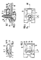
- Fig. 1 eine Ausführungsform der Blechmutter in Seitenansicht,
- Fig. 2 die Blechmutter in Draufsicht,
- Fig. 3 die gleiche Blechmutter im montierten Zustand im Schnitt,
- Fig. 4 die montierte Blechmutter in Draufsicht,
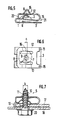
- Fig. 5 eine weitere Ausführungsform der erfindungsgemäßen Blechmutter in Seitenansicht,
- Fig. 6 die gleiche Blechmutter in Draufsicht und
- Fig. 7 die gleiche Blechmutter im montierten Zustand im Schnitt.
- 1 shows an embodiment of the sheet metal nut in side view,
- 2 the sheet metal nut in plan view,
- 3 the same sheet metal nut in the assembled state in section,
- 4 the assembled sheet metal nut in plan view,
- 5 shows a further embodiment of the sheet metal nut according to the invention in side view,
- Fig. 6 shows the same sheet metal nut in plan view
- Fig. 7 the same sheet metal nut in the assembled state in section.
Die vorliegende Blechmutter dient, wie aus Fig. 3 ersichtlich, zur Verbindung plattenförmiger Bauteile 17, 18 und besteht im wesentlichen aus einem Gewindeschenkel 1 mit einem ausgeprägten Gewindegang 2 und einem mit dem Gewindeschenkel 1 U-förmig verbundenen Klammerschenkel 3 mit einem Durchgangsloch 4 zum Durchführen einer in den Gewindegang eindrehbaren Blechschraube 5. Der Gewindeschenkel 1 ist hierbei zum Klammerschenkel 3 hin etwas geneigt, so daß beim Aufdrücken der Blechmutter auf die Kante 19 der Trägerplatte 17 der Gewindeschenkel 1 etwas hochgebogen und die Trägerplatte 17 zwischen Gewindeschenkel 1 und Klammerschenkel 3 fest eingeklemmt wird. Das Durchgangsloch 4 ist von einem Zentrierring 6 umgeben, der beim Aufdrücken der Blechmutter in das entsprechende Befestigungsloch 20 der Trägerplatte 17 einrastet.The present sheet metal nut serves, as can be seen from FIG. 3, to connect plate-
Bei der in den Fig. 1 bis 4 dargestellten Blechmutter sind zwei Sicherungslappen 7 und 8 angeformt und zur Gewindeprägung 2 hin über Verbindungsbogen 14 und 15 herumgeführt. Diese Lappen 7 und 8 sind mit bogenförmigen Klemmkanten 9 versehen, welche sich beim Eindrehen der Blechschraube 5 in den Gewindegang 2 von beiden Seiten eng an den Gewindekern 10 anlegen, von diesem auseinandergedrückt werden und durch die dabei in den Verbindungsbögen 14 und 15 erzeugte Rückstellkraft die Schraube 5 gegen selbsttätiges Lösen sichern. Es versteht sich, daß der Abstand "a" zwischen den Kanten 9 im Anlieferungszustand der Blechmutter kleiner sein muß als der Kerndurchmesser "k" der Schraube 5, und zwar um so viel kleiner, daß eine ausreichende Klemmkraft erzeugt wird.In the sheet metal nut shown in FIGS. 1 to 4, two
Beide Sicherungslappen 7 und 8 sind auf einer Seite der Gewindeprägung 2 angeformt und zwar an dem in Aufsteckrichtung der Blechmutter vorderen Ende 21 des Schenkels 1. Hierbei ist der eine Lappen 7 mittig am Schenkel 1 angeformt und greift auch von dieser Seite in das Schraubengewinde 11 ein. Der andere Lappen 8 hingegen wird von der Rückseite her an das Schraubengewinde 11 herangeführt und ist über zwei am Durchgangsbereich der Schraube 5 vorbeigeführte Stege 12 mit dem vorderen Ende 21 des Gewindeschenkels 1 verbunden. Die Stege 12 verlaufen parallel zum vorderen Lappen 7 und sind von diesem durch je einen schmalen Schlitz 13 getrennt. Die Schlitze 13 sind bis zum Gewindeschenkel 1 heruntergezogen, um das elastische Verhalten der Verbindungsbögen 14 und 15 voll auszunutzen. Um ein gleichmäßiges Ausweichen der Sicherungslappen 7,8 zu gewährleisten, haben die Stege 12 zusammen die gleiche Breite wie der vordere Lappen 7 bzw. dessen Verbindungsbogen 14.Both
Beide Lappen 7 und 8 wie auch die Stege 12 liegen etwa in einer Ebene senkrecht zur Achse der Schraube 5. Dadurch wird erreicht, daß der vordere Lappen 7 bis zum Beginn des Bogens 14 nur auf Druck und die Stege 12 bis zur gleichen Stelle des Bogens 15 nur auf Zug beansprucht werden, während die Bögen 14 und 15 auf Biegung beansprucht werden. Wie aus Fig. 3 und 4 ersichtlich, wird beim Eindrehen der Schraube 5 der mittlere Bogen 14 in Richtung des Pfeiles A nach außen gedrückt, während die beiden äußeren Bögen 15 in Richtung des Pfeiles B gezogen werden und zwar jeweils zur Hälfte des Betrages, den der Abstand "a" zwischen den halbkreisförmigen Kanten 9 im entspannten Zustand kleiner ist als der Kerndurchmesser "k" der Schraube 5.Both
Bei dem in den Fig. 5 bis 7 dargestellten Ausführungsbeispiel sind die Stege 12 über eine wellenförmige Umlenkung 16 am vorderen Lappen 7 angeformt und mit diesem zusammen über bogenförmige Verbindungsstreifen 15 mit dem Gewindeschenkel 1 verbunden, wobei die Verbindungsbogen 15 zweckmäßigerweise wieder die gleiche Breite haben wie die Stege 12. Außerdem ist der rückwärtige Sicherungslappen 8 mit einem abgewinkelten Ende 22 auf dem Gewindeschenkel 1 verschieblich abgestützt.In the embodiment shown in FIGS. 5 to 7, the
Wie aus Fig. 6 und 7 ersichtlich, wird der vordere, im Bild rechte Sicherungslappen 7 beim Eindrehen der Schraube 5 um die halbe Differenz zwischen Kantenabstand "a" und Gewindekerndurchmesser "k" durch elastisches Nachgeben der Verbindungsbögen 15 nach der Aufsteckseite hin verschoben, während der rückwärtige Lappen 8 gleichzeitig um den gleichen Betrag in entgegengesetzter Richtung verdrängt wird. Hierbei streckt sich die wellenförmige Umlenkung 16 um die volle Differenz in die Länge und bewirkt aufgrund ihrer elastischen Rückstellkraft das Andrücken der Kanten 9 der Sicherungslappen 7 und 8 an dem Gewindekern 10. Das abgewinkelte Ende 22 sorgt hierbei dafür, daß der rückwärtige Sicherungslappen 8 nicht nach unten abknickt, sondern seine Lage etwa senkrecht zur Schraubenachse beibehält.As can be seen from FIGS. 6 and 7, the
Claims (5)
dadurch gekennzeichnet,
daß beide Sicherungslappen (7) und (8) auf einer Seite der Gewinderprägung (2) angeformt sind und zwar derart, daß der von der Gegenseite in das Gewinde der Schraube (5) eingreifende Gegenlappen (8) über zwei am Durchgangsbereich der Schraube (5) vorbeigeführte Stege (12) mit dem Gewindeschenkel (1) verbunden ist und die Sicherungslappen (7) und (8) etwa senkrecht zur Schraubenachse gerichtet sind.1.Self-locking clamp-like sheet metal nut, consisting of a leg with a pronounced thread and a clip leg provided with a through hole, as well as two locking tabs formed on the thread leg and bent around for embossing the thread, whose opposing, arcuate clamping edges have a smaller distance apart than the core diameter of the sheet metal screw to be screwed in ,
characterized,
that both locking tabs (7) and (8) are formed on one side of the thread embossing (2) in such a way that the counter-tab (8) engaging in the thread of the screw (5) from the opposite side over two at the passage area of the screw (5 ) led by webs (12) with the threaded leg (1) and the locking tabs (7) and (8) are directed approximately perpendicular to the screw axis.
Applications Claiming Priority (2)
| Application Number | Priority Date | Filing Date | Title |
|---|---|---|---|
| DE19853536473 DE3536473A1 (en) | 1985-10-12 | 1985-10-12 | SELF-LOCKING CLAMP TYPE NUT |
| DE3536473 | 1985-10-12 |
Publications (3)
| Publication Number | Publication Date |
|---|---|
| EP0220526A1 true EP0220526A1 (en) | 1987-05-06 |
| EP0220526B1 EP0220526B1 (en) | 1989-04-26 |
| EP0220526B2 EP0220526B2 (en) | 1993-01-13 |
Family
ID=6283456
Family Applications (1)
| Application Number | Title | Priority Date | Filing Date |
|---|---|---|---|
| EP86113591A Expired - Lifetime EP0220526B2 (en) | 1985-10-12 | 1986-10-02 | Self-locking clip-like sheet metal nut |
Country Status (5)
| Country | Link |
|---|---|
| US (1) | US4714392A (en) |
| EP (1) | EP0220526B2 (en) |
| JP (1) | JPH0641767B2 (en) |
| DE (2) | DE3536473A1 (en) |
| ES (1) | ES2008042T5 (en) |
Cited By (5)
| Publication number | Priority date | Publication date | Assignee | Title |
|---|---|---|---|---|
| FR2679302A1 (en) * | 1991-07-15 | 1993-01-22 | Gobin Daude | Improved elastic nut |
| FR2698134A1 (en) * | 1992-11-17 | 1994-05-20 | Gobin Daude | Improvement to pinch nuts - includes two main plates, one having hole and other having nut indentation, with elastic connector having two segments connecting these two plates |
| EP0778420A1 (en) * | 1995-12-04 | 1997-06-11 | Eaton Corporation | Clip-on fastening device |
| EP1988300A3 (en) * | 2007-04-27 | 2010-12-15 | Lisi Automotive Rapid | Device for fixing components to each other with the help of a clip which can be slid onto a component |
| WO2016193013A1 (en) * | 2015-06-01 | 2016-12-08 | A. Raymond Et Cie | Device for mounting an attachment part to a carrier part |
Families Citing this family (32)
| Publication number | Priority date | Publication date | Assignee | Title |
|---|---|---|---|---|
| JPH0451207Y2 (en) * | 1987-03-31 | 1992-12-02 | ||
| US4897005A (en) * | 1987-04-01 | 1990-01-30 | Buell Industries, Inc. | Gutted U-nut |
| US4826375A (en) * | 1987-08-17 | 1989-05-02 | Eaton Corporation | Variable diameter screw fastener |
| JPH0251607A (en) * | 1988-08-12 | 1990-02-21 | Nippon Chemicon Corp | Stopping device |
| DE3910423A1 (en) * | 1989-03-31 | 1990-10-04 | Raymond A Fa | CLAMP TYPE NUT FOR AUTOMATIC ASSEMBLY |
| DE3938547A1 (en) * | 1989-11-21 | 1991-05-23 | Ford Werke Ag | COMPONENT FASTENING IN MOTOR VEHICLE BODIES WITH A TIN NUT AND A BOLT |
| US5256018A (en) * | 1992-11-02 | 1993-10-26 | Eaton Corporation | Clip-on fastener |
| US5423646A (en) * | 1993-02-24 | 1995-06-13 | Buell Industries, Inc. | U-nut |
| DE4413498C1 (en) * | 1994-04-19 | 1995-08-17 | Ernst Horlacher | Self-securing sheet metal nut |
| CA2171918C (en) * | 1995-05-26 | 2000-06-06 | Michael G. Gagnon | U-nut |
| US5603524A (en) * | 1995-12-01 | 1997-02-18 | General Motors Corporation | Releasable fastener for air bag deployment cover |
| DE19607687B4 (en) * | 1996-02-29 | 2007-10-31 | BSH Bosch und Siemens Hausgeräte GmbH | Connection of thin-walled parts |
| US5951224A (en) * | 1996-04-10 | 1999-09-14 | Permanent Technologies, Inc. | Locking nut and bolt system |
| IT236035Y1 (en) * | 1997-04-10 | 2000-07-26 | Fiat Auto Spa | FIXING SPRING. |
| DE19748962C1 (en) * | 1997-11-06 | 1999-06-24 | Raymond A & Cie | Sheet metal fastening nut |
| US20050029778A1 (en) * | 2003-08-06 | 2005-02-10 | Robert Weber | Mounting bracket with fastener retention |
| DE102004052332B4 (en) * | 2004-10-27 | 2006-09-14 | Springfix-Befestigungstechnik Gmbh | Clip-mother |
| DE102005024712B4 (en) * | 2005-05-30 | 2008-03-13 | A. Raymond Et Cie | spring nut |
| US20070224018A1 (en) * | 2006-03-03 | 2007-09-27 | Deperro Charles A | Fastening device |
| US7597342B2 (en) | 2006-05-26 | 2009-10-06 | Autoliv Asp, Inc. | Energy absorbing feature for inflatable curtain airbag |
| US20100310338A1 (en) * | 2007-11-29 | 2010-12-09 | Itw Metal Fasteners, S.L. | Speed nut |
| BRPI1008925A2 (en) * | 2009-02-18 | 2016-03-15 | Honda Motor Co Ltd | assembly structure of component parts |
| DE102010022198A1 (en) * | 2010-05-20 | 2011-11-24 | A. Raymond Et Cie S.C.S. | spring clip |
| CN104105891B (en) * | 2012-02-10 | 2016-10-12 | 百乐仕株式会社 | Fixture and there is the component mounting structure of this fixture |
| US8950993B2 (en) * | 2012-05-02 | 2015-02-10 | Brainwave Research Corporation | Speed nut and assembly |
| CN103398070A (en) * | 2013-07-29 | 2013-11-20 | 无锡市张泾宇钢机械厂 | Dual-deformation elastic nut |
| JP5874156B2 (en) * | 2014-01-31 | 2016-03-02 | 大阪フォーミング株式会社 | Clip nut |
| WO2016116170A1 (en) * | 2015-01-23 | 2016-07-28 | Barco Nv | Connecting device for improved alignment |
| CN104930037B (en) * | 2015-06-18 | 2017-01-18 | 嘉兴汉工汽车紧固件有限公司 | Self-tapping nail nut seat, detachable assembly applying same and machining process |
| US11148615B2 (en) | 2015-06-19 | 2021-10-19 | Henniges Automotive Sealing Systems North America, Inc. | Fixed window assembly for a vehicle and method of manufacturing same |
| WO2016205799A1 (en) | 2015-06-19 | 2016-12-22 | Henniges Automotive Sealing Systems North America Inc. | Trim strip assembly for vehicle and method of manufacturing the same |
| US11585358B2 (en) * | 2017-02-28 | 2023-02-21 | 3M Innovative Properties Company | Attachment device and related methods |
Citations (3)
| Publication number | Priority date | Publication date | Assignee | Title |
|---|---|---|---|---|
| US3308708A (en) * | 1964-08-14 | 1967-03-14 | Tinnerman Products Inc | Fastening device |
| DE2849840C2 (en) * | 1978-11-17 | 1982-09-16 | E. Winkemann & Co, 5970 Plettenberg | U-nut made of spring steel sheet |
| EP0106451A2 (en) * | 1982-09-30 | 1984-04-25 | Eaton Corporation | Improved fastening device |
Family Cites Families (6)
| Publication number | Priority date | Publication date | Assignee | Title |
|---|---|---|---|---|
| US22049A (en) * | 1858-11-09 | Thomas | ||
| US21769A (en) * | 1858-10-12 | Machine fob chamfering and crozing barrels | ||
| US2140064A (en) | 1937-10-04 | 1938-12-13 | Albert H Tinnerman | Fastening device |
| US2771113A (en) * | 1953-08-18 | 1956-11-20 | Tinnerman Products Inc | Sheet metal lock nut with spring locking arm |
| GB1082688A (en) | 1963-07-12 | 1967-09-06 | Firth Cleveland Fastenings Ltd | Improvements in or relating to sheet-metal nuts |
| DE3121771C2 (en) | 1981-05-26 | 1990-05-31 | Mecano-Simmonds Gmbh, 6900 Heidelberg | One-piece clamp-like sheet metal nut |
-
1985
- 1985-10-12 DE DE19853536473 patent/DE3536473A1/en not_active Withdrawn
-
1986
- 1986-10-02 ES ES86113591T patent/ES2008042T5/en not_active Expired
- 1986-10-02 EP EP86113591A patent/EP0220526B2/en not_active Expired - Lifetime
- 1986-10-02 DE DE8686113591T patent/DE3663067D1/en not_active Expired
- 1986-10-09 JP JP61241191A patent/JPH0641767B2/en not_active Expired - Lifetime
- 1986-10-10 US US06/917,484 patent/US4714392A/en not_active Expired - Lifetime
Patent Citations (3)
| Publication number | Priority date | Publication date | Assignee | Title |
|---|---|---|---|---|
| US3308708A (en) * | 1964-08-14 | 1967-03-14 | Tinnerman Products Inc | Fastening device |
| DE2849840C2 (en) * | 1978-11-17 | 1982-09-16 | E. Winkemann & Co, 5970 Plettenberg | U-nut made of spring steel sheet |
| EP0106451A2 (en) * | 1982-09-30 | 1984-04-25 | Eaton Corporation | Improved fastening device |
Cited By (8)
| Publication number | Priority date | Publication date | Assignee | Title |
|---|---|---|---|---|
| FR2679302A1 (en) * | 1991-07-15 | 1993-01-22 | Gobin Daude | Improved elastic nut |
| FR2698134A1 (en) * | 1992-11-17 | 1994-05-20 | Gobin Daude | Improvement to pinch nuts - includes two main plates, one having hole and other having nut indentation, with elastic connector having two segments connecting these two plates |
| EP0778420A1 (en) * | 1995-12-04 | 1997-06-11 | Eaton Corporation | Clip-on fastening device |
| EP1988300A3 (en) * | 2007-04-27 | 2010-12-15 | Lisi Automotive Rapid | Device for fixing components to each other with the help of a clip which can be slid onto a component |
| WO2016193013A1 (en) * | 2015-06-01 | 2016-12-08 | A. Raymond Et Cie | Device for mounting an attachment part to a carrier part |
| CN108124458A (en) * | 2015-06-01 | 2018-06-05 | A·雷蒙德公司 | For installing component to be fixed on to the equipment on load bearing component |
| US10830267B2 (en) | 2015-06-01 | 2020-11-10 | A. Raymond Et Cie | Device for mounting an attachment part to a carrier part |
| CN108124458B (en) * | 2015-06-01 | 2021-05-04 | A·雷蒙德公司 | Device for fixing a mounting part to a carrier part |
Also Published As
| Publication number | Publication date |
|---|---|
| ES2008042B3 (en) | 1989-07-01 |
| EP0220526B2 (en) | 1993-01-13 |
| JPH0641767B2 (en) | 1994-06-01 |
| US4714392A (en) | 1987-12-22 |
| EP0220526B1 (en) | 1989-04-26 |
| DE3663067D1 (en) | 1989-06-01 |
| JPS6293510A (en) | 1987-04-30 |
| DE3536473A1 (en) | 1987-04-16 |
| ES2008042T5 (en) | 1995-08-01 |
Similar Documents
| Publication | Publication Date | Title |
|---|---|---|
| EP0220526B1 (en) | Self-locking clip-like sheet metal nut | |
| WO2012048686A1 (en) | Cage nut | |
| EP1424520A1 (en) | Mounting device for an oblong article, in particular wiring harness | |
| CH618251A5 (en) | ||
| DE3235329C1 (en) | Screwless band clamp | |
| DE60203838T2 (en) | Device for holding screws with a hook | |
| EP0232917A2 (en) | Method as well as clamp and support for the mounting of visual display devices | |
| EP0694725B1 (en) | Flat spring clamp | |
| EP0780923B1 (en) | Clamp for connecting a conductor end with a contact | |
| DE102018130388A1 (en) | TOLERANCE COMPENSATING DEVICE | |
| DE2907656A1 (en) | PAPER CLIP AND FILING DEVICE | |
| DE19730269C2 (en) | Device for fastening a first part to a second part | |
| EP0302135A1 (en) | Clip for attaching flat objects to a supporting device | |
| DE2801615A1 (en) | SKI BRAKE | |
| DE2322265C2 (en) | Fastening device for joining and holding flat electric cables | |
| DE10236550A1 (en) | Holding device for a cable harness shoe element | |
| DE2946993C2 (en) | ||
| DE3326070A1 (en) | Clamp with a broad strip | |
| EP0583580A2 (en) | Clevis joint | |
| DE2832386C3 (en) | Arrangement for the detachable fastening of two components to one another, in particular the brake pedal of a motor vehicle | |
| DE2336184B2 (en) | Spring clip that can be fastened in a round hole in a plate | |
| EP2022928A1 (en) | Lamella with lateral guide nipples | |
| DE2417942A1 (en) | FIXING DEVICE FOR PIPES OR THE SAME | |
| EP0089535B1 (en) | Bolted abutment connection for grids | |
| AT401285B (en) | PIPE CONNECTION |
Legal Events
| Date | Code | Title | Description |
|---|---|---|---|
| PUAI | Public reference made under article 153(3) epc to a published international application that has entered the european phase |
Free format text: ORIGINAL CODE: 0009012 |
|
| AK | Designated contracting states |
Kind code of ref document: A1 Designated state(s): DE ES FR GB IT SE |
|
| 17P | Request for examination filed |
Effective date: 19870525 |
|
| 17Q | First examination report despatched |
Effective date: 19880222 |
|
| GRAA | (expected) grant |
Free format text: ORIGINAL CODE: 0009210 |
|
| AK | Designated contracting states |
Kind code of ref document: B1 Designated state(s): DE ES FR GB IT SE |
|
| ITF | It: translation for a ep patent filed |
Owner name: DE DOMINICIS & MAYER S.R.L. |
|
| GBT | Gb: translation of ep patent filed (gb section 77(6)(a)/1977) | ||
| REF | Corresponds to: |
Ref document number: 3663067 Country of ref document: DE Date of ref document: 19890601 |
|
| ET | Fr: translation filed | ||
| PLBI | Opposition filed |
Free format text: ORIGINAL CODE: 0009260 |
|
| 26 | Opposition filed |
Opponent name: MECANO-SIMMONDS GMBH Effective date: 19900126 |
|
| ITTA | It: last paid annual fee | ||
| PUAH | Patent maintained in amended form |
Free format text: ORIGINAL CODE: 0009272 |
|
| STAA | Information on the status of an ep patent application or granted ep patent |
Free format text: STATUS: PATENT MAINTAINED AS AMENDED |
|
| RAP2 | Party data changed (patent owner data changed or rights of a patent transferred) |
Owner name: A. RAYMOND KG |
|
| 27A | Patent maintained in amended form |
Effective date: 19930113 |
|
| AK | Designated contracting states |
Kind code of ref document: B2 Designated state(s): DE ES FR GB IT SE |
|
| ITF | It: translation for a ep patent filed |
Owner name: DE DOMINICIS & MAYER S.R.L. |
|
| GBTA | Gb: translation of amended ep patent filed (gb section 77(6)(b)/1977) |
Effective date: 19930317 |
|
| ET3 | Fr: translation filed ** decision concerning opposition | ||
| EAL | Se: european patent in force in sweden |
Ref document number: 86113591.1 |
|
| ITPR | It: changes in ownership of a european patent |
Owner name: CAMBIO RAGIONE SOCIALE;A. RAYMOND GMBH & CO. KG |
|
| REG | Reference to a national code |
Ref country code: ES Ref legal event code: DC2A Kind code of ref document: T5 Effective date: 19950801 |
|
| REG | Reference to a national code |
Ref country code: GB Ref legal event code: 732E |
|
| REG | Reference to a national code |
Ref country code: GB Ref legal event code: IF02 |
|
| PGFP | Annual fee paid to national office [announced via postgrant information from national office to epo] |
Ref country code: DE Payment date: 20050929 Year of fee payment: 20 |
|
| PGFP | Annual fee paid to national office [announced via postgrant information from national office to epo] |
Ref country code: ES Payment date: 20050930 Year of fee payment: 20 |
|
| PGFP | Annual fee paid to national office [announced via postgrant information from national office to epo] |
Ref country code: GB Payment date: 20051003 Year of fee payment: 20 |
|
| PGFP | Annual fee paid to national office [announced via postgrant information from national office to epo] |
Ref country code: SE Payment date: 20051017 Year of fee payment: 20 |
|
| PGFP | Annual fee paid to national office [announced via postgrant information from national office to epo] |
Ref country code: FR Payment date: 20051021 Year of fee payment: 20 |
|
| PGFP | Annual fee paid to national office [announced via postgrant information from national office to epo] |
Ref country code: IT Payment date: 20051025 Year of fee payment: 20 |
|
| PG25 | Lapsed in a contracting state [announced via postgrant information from national office to epo] |
Ref country code: GB Free format text: LAPSE BECAUSE OF EXPIRATION OF PROTECTION Effective date: 20061001 |
|
| PG25 | Lapsed in a contracting state [announced via postgrant information from national office to epo] |
Ref country code: ES Free format text: LAPSE BECAUSE OF EXPIRATION OF PROTECTION Effective date: 20061003 |
|
| REG | Reference to a national code |
Ref country code: GB Ref legal event code: PE20 |
|
| EUG | Se: european patent has lapsed | ||
| REG | Reference to a national code |
Ref country code: ES Ref legal event code: FD2A Effective date: 20061003 |