EP0220149A2 - Isolierungsdurchdringende Multilehre-Multidraht-Klemme - Google Patents
Isolierungsdurchdringende Multilehre-Multidraht-Klemme Download PDFInfo
- Publication number
- EP0220149A2 EP0220149A2 EP86850356A EP86850356A EP0220149A2 EP 0220149 A2 EP0220149 A2 EP 0220149A2 EP 86850356 A EP86850356 A EP 86850356A EP 86850356 A EP86850356 A EP 86850356A EP 0220149 A2 EP0220149 A2 EP 0220149A2
- Authority
- EP
- European Patent Office
- Prior art keywords
- slot
- ribs
- wire
- terminal
- free ends
- Prior art date
- Legal status (The legal status is an assumption and is not a legal conclusion. Google has not performed a legal analysis and makes no representation as to the accuracy of the status listed.)
- Withdrawn
Links
Images

Classifications
-
- H—ELECTRICITY
- H01—ELECTRIC ELEMENTS
- H01R—ELECTRICALLY-CONDUCTIVE CONNECTIONS; STRUCTURAL ASSOCIATIONS OF A PLURALITY OF MUTUALLY-INSULATED ELECTRICAL CONNECTING ELEMENTS; COUPLING DEVICES; CURRENT COLLECTORS
- H01R4/00—Electrically-conductive connections between two or more conductive members in direct contact, i.e. touching one another; Means for effecting or maintaining such contact; Electrically-conductive connections having two or more spaced connecting locations for conductors and using contact members penetrating insulation
- H01R4/24—Connections using contact members penetrating or cutting insulation or cable strands
- H01R4/2416—Connections using contact members penetrating or cutting insulation or cable strands the contact members having insulation-cutting edges, e.g. of tuning fork type
- H01R4/242—Connections using contact members penetrating or cutting insulation or cable strands the contact members having insulation-cutting edges, e.g. of tuning fork type the contact members being plates having a single slot
- H01R4/2437—Curved plates
- H01R4/2441—Curved plates tube-shaped
Definitions
- the present invention pertains generally to the field of telecommunications and more particularly to terminal blocks and modules.
- Insulation displacement terminals are widely used in the telecommunications industry for the interconnection of equipment and distribution lines.
- the terminals provide for a quick, mechanically secure and electrically sound connection without the use of solder, whereby large numbers of wires may be connected with a minimum of labor.
- the typical prior art insulation displacement terminal consists of a metal cylinder which is "split" to provide a longitudinal seam or slot, with opposing sides of the cylinder forming a pair of jaws. As a wire is inserted into the slot laterally of its length the jaws slice through any insulation on the wire and crimpingly engage the conductor portion of the wire. More than one wire can be terminated between the jaws of the split cylinder provided that the wires are of the same gauge. However, if the wires are of different gauge, the larger diameter wire spreads the jaws of the terminal away from the smaller diameter wire resulting in a broken or intermittent connection. Thus, the typical prior art terminal cannot be used to terminate wires of different gauge.
- wires to be connected are of a uniform guage.
- the above-described terminal is well suited to the task.
- wire wrap terminals which can accommodate a number of different gauges must be used.
- connecting wires via wire wrap terminals is less efficient than using insulation displacement terminals, making it a less desirable alternative. Accordingly, there is a need for a multiguage and multiwire insulation displacement terminal.
- the present invention provides a multigauge-multiwire insulation displacement terminal which can terminate and connect two or more wires of different gauge.
- the terminal comprises a cylindrical hollow barrel portion including a longitudinal seam forming opposing jaws and defining a continuous wire receiving slot.
- a rib cage portion coaxially extends from the hollow barrel portion and includes a spine extending from the side of the barrel portion radially opposite the continuous slot.
- One or more transversely oriented ribs extend from the spine to respective free ends which are in radial alignment with the continuous slot. The free ends of the ribs are further aligned in opposition to one another to form a discontinuous slot which is in axial alignment with the continuous slot, with the free ends of opposing ribs offset from one another.
- a wire is inserted in the continuous slot laterally of its axis so that the jaws slice through any insulation on the wire and crimpingly engage the conductor portion of the wire.
- the wire may be displaced or pushed from the jaws into the discontinuous slot and be gripped by two or more opposing ribs. Accordingly, one or more wires may be held between the free ends of opposing ribs in the discontinuous slot with the individual ribs independently biased against the wires to accommodate wires of different gauges. And, another additional wire may thus be held between the jaws of the hollow barrel portion whereby two or more wires of different gauge may be terminated and connected.
- the terminal is mounted within a generally cylindrical housing constructed of non-conductive material.
- the housing includes a bottom floor against which the bottom ribs of the rib cage portion may rest and a front wall adjacent the free ends of the ribs to provide axial and radial support for the ribs, respectively. Accordingly, deformation of the ribs by the application of axial force during insertion of a wire, or from the radially outward force applied when a wire which is pulled in the direction of its length outwardly from the terminal, is avoided.
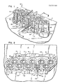
- Module 10 includes a housing 15 molded of relatively rigid non-conductive plastic, which is formed to provide ten cylindrical wire connector units 30. In use, module 10 is preferably mounted to a panel 11.
- housing 15 includes a pair of mounting shoulders 74 and 75 and four flexible bridge members 16-19 which are adapted to flex past panel tabs 21-24, respectively, to permit snap-in mounting of module 10 in panel aperture 12.
- Each wire connector unit 30 includes a cylindrical housing 31 which holds a stamped and formed metal terminal 32.
- the cylindrical housings 31 are formed integrally with other housings as illustrated. Alternatively, however, the wire connector unit housings can be formed and mounted individually if desired.
- Housing 31 is generally cylindrical, and includes a first end 35 and a second end 36, such that module 10 is double-ended.
- Terminal 32 is also double-ended, including a first end 40 and a second end 41.
- end 40 is adapted to terminate two or more wires of different gauge, while end 41 is adapted to receive one or more wires of the same gauge.
- end 41 of terminal 32 is adapted to terminate 22, 24 and 26 gauge wires, and is stamped and formed from .014 inch phosphor-bronze.
- certain dimensions for terminal 32 given herein relate to the material properties of phosphor-bronze. It is, however, contemplated that terminal 32 may be constructed of other metals and alloys having different properties provided that, to the extent necessary, material thickness and terminal dimensions are adjusted to compensate for differences in material strength, resiliency, hardness, etc.
- terminals may also be formed from beryllium-copper, nickel-silver and spring brass.
- End 41 of terminal 32 and end 36 of housing 31 are of a design which was disclosed in co-pending application Serial No. 658,268, filed October 5, 1984, and entitled "Electrical Connector Module with Multiple Connector Housings", by Pohl. Accordingly, for the sake of brevity this aspect of the present invention will not be described in detail herein.
- end 41 of terminal 32 consists of a split cylinder design which includes a slot 45 into which wires may be inserted laterally of their length for termination and connec tion.
- end 41 includes a pair of tine members 46 and 47 which, as explained in more detail below, are for mounting terminal 32 in housing 31.
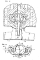
- End 40 includes a first split cylinder portion 60 resembling a cylindrical hollow barrel.
- portion 60 has an outside diameter D of .106 inches (FIGURE 8).
- Portion 60 includes a longitudinal seam forming opposing jaws 76 and 77 and defining a continuous insulation displacing wire receiving slot 61 into which wires may be inserted laterally of their lengths.
- slot 61 has a nominal width 175 of .006 inches (FIGURE 8).
- jaw 76 extends axially beyond the jaw 77.
- slot 61 is flared outwardly to provide a wire guide 62 to funnel wires into slot 61 as they are inserted.
- a recess 63 including a cutting edge for trimming the ends off wires as they are inserted.
- End 40 of terminal 32 further includes a rib cage portion 65 including an arcuate spine 68 which extends from the rear wall 63 of portion 60, and a plurality of resilient ribs, or fingers, 70-75.
- ribs 70 and 73 as shown in FIGURE 7, each of ribs 70-75 include a first extent 80 which extends tangentially away from arcuate spine 68, a bend 81 of acute angle, and a second extent 82, or free end, which is slightly inclined with respect to a line transverse and tangent to slot 61.
- bend 81 preferably has a radius R of .019 inches.
- the centerpoint for radius R is preferably offset from the axis of terminal 32 a distance 164 of .060 inches and a distance 166 of .014 inches in the "x" and "y" directions, respectively.
- the angle A of bend 81 is preferably approximately 30 degrees.
- the circumferential width 165 of spine 68 is preferably .054 inches. With the exception of rib 72, extents 80 and 82 of ribs 70-75 are approximately .026 inches in width.
- each of ribs 70-75 are axially offset from one another, or staggered, and terminate at the offset, opposing tips 90, which have a generally flat or planar end profile.
- Rib 70 in addition to being opposed to ribs 73, is also opposed to a corner 92 of jaw 76 of cylinder portion 60.
- Each of ribs 70-75 are of substantially the same shape except for rib 72, which by virture of its "bottom" position is approximately twice the width of the remaining ribs.
- rib 72 is deemed to have a "centerline" 169 which assumes rib 72 is of similar width to the other ribs. Due to the excess width of rib 72, it includes a notch 168 which provides inward clearance for the corner 167 of rib 75.
- Ribs 70-75 are aligned with respect to the axis of the terminal to form a discontinuous slot 94, the approximate centerline of which is illustrated with dotted-line 95.
- the innermost extent 167 of tips 90 extend to the centerline of slot 94, such that if opposing ones of tips 90 where not offset they would just touch one another. It is contemplated, however, that opposing tips, in their relaxed condition, could be spaced apart up to .006 inches.
- the preferred spacing is .006 inches maximum.
- the spacing 170 between the centerlines of longitudinally adjacent ribs is preferably .040 inches, while the offset between centerlines of opposing ribs 70 and 73, 71 and 74, and 72 and 75, is preferably .020 inches.
- Rib 70 is spaced a distance 171 of .027 inches to its centerline from the "bottom" edge of jaw 77, while rib 73 is spaced a distance 173 of .027 inches from the "bottom” edge of jaw 76.
- Ribs 70-75 are generally resiliently flexible about spine 68 when they are spread away from slot 94. Thus, ribs 70-75 form a plurality of wire pincers. As will be explained below in more detail, discontinuous slot 94 is provided to receive up to two, and possibly three, wires pushed or displaced from slot 61. Accordingly, ribs 70-75 are formed to facilitate the movement of a wire through discontinuous slot 94 and to crimpingly engage the conductor portion of each wire as they travel in the slot, despite differences in their gauge.
- the tips 90 of ribs 70-75 are slightly enlarged or flared in order to narrow the gap between axially adjacent ribs.
- the edge of each tip is inclined approximately 13 degrees with respect to the centerline 95 of slot 94 so as to slope toward the centerline with respect to the direction of wire travel therealong, to prevent wires from catching on an edge of a rib.
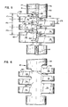
- End 35 is generally cylindrical in shape and includes a pair of diametrically opposed wire slots 100 and 101, one of which is aligned with slots 61 and 94 of terminal 32.
- slots 100 and 101 are for holding a wire in position before insertion, as in the case of wire 105.
- slot 100 or the slot which is aligned with the discontinuous slot 94 of a terminal 32, is designed to positively grip the insulation on an inserted wire to provide strain relief.
- each of slots 100 include a pair of opposing lip portions 106 and 107 (see FIGURE 2).
- the same strain relief system is also disclosed in the above-referenced U. S. patent application by Pohl, and reference may be had to that application for further details of this feature if desired.
- end 35 of housing 31 are recessed on diametrically opposed sides to provide a pair of irregularly shaped channels 110 and 111.
- channels 110 and 111 extend from the "top" of end 35 to the bottom floor 51 thereof.
- a nest portion 120 is provided at the bottom of end 35 and includes an inwardly protruding portion, or front wall, 121 and a rear wall 122, with the sides of the nest provided by the lower extent of channels 110 and 111.
- walls 121 and 122 each extend from the floor 51 to the respective ledges 125 and 126.
- the wall 121 is slotted integrally with slot 100, with the portion of the slot cutting through wall 121 having an inclined floor 130 which extends upwardly and outwardly from floor 51. While inclined floor 130 is provided in the preferred embodiment of the present invention, the incline is not essential to the invention. Rather, it is only necessary that the slot extend to floor 51 to provide for wire insertion to the bottom of the terminal 32.
- Wall 122 is slotted integrally with slot 101, but the slot does not extend to floor 51, as it is not required.
- housing 31 includes an annular terminal retaining portion 50 which provides on one side floor 51 and on the other side a stop for tines 46 and 47.
- Housing 31 further includes diametrically opposed and longitudinally extending grooves 48 and 49. Accordingly, terminal 32 may be mounted in housing 31 by inserting it into end 35 and past retaining portion 50 so that tines 46 and 47 snap into place in grooves 48 and 49. Accordingly, terminal 32 is axially retained in housing 31 with ribs 72 and 75 resting on floor 51, and tine 46 and 47 on the opposite side of retaining portion 50.
- Tines 46 and 47 in cooperation with grooves 48 and 49, also provide for aligning the slots of terminal 32 with those of housing 31 and for restricting the rotation of terminal 32 in the housing.
- terminal 32 is mounted in housing 31 so that rib cage portion 65 is nested within nest 120, with the lower extent of spine 68 adjacent the rear wall 122 and with the free ends 82 of ribs 70-75 generally adjacent front wall 121.
- the tips 90 of free ends 82 protrude to a limited extent into the space interior of, or "behind", slot 61.
- the present invention provides a multigauge-multiwire insulation displacement terminal.
- the embodiment illustrated herein is capable of connecting and terminating, on the rib caged end, up to three, and possibly four, wires of different gauge.
- the terminal is limited to terminating wires within a given range of gauge, although it may be adapted for different ranges.
- the terminal is known to be adaptable to a gauge range of approximately four.
- the preferred embodiment disclosed herein may be used to terminate wires of gauges 22, 24, and 26. However, it could be adapted for 24, 26 and 28 etc. Nonetheless, the number of different wire gauges encountered in any given application is generally limited to two, and are usually either 22, 24 or 26 gauge.
- a terminal adapted to this gauge range may accommodate the majority of multigauge wiring applications. And, if desired, other ranges may be provided for by altering the width of and spacing between ribs 70-75 as required to accommodate differences in wire diameters. Moreover, it is contemplated that further "upper" ribs (70, 73) may be added to accommodate a greater number of wires, for example four or five, if desired.
- the connector unit 30 may be used to terminate up to at least three wires of different gauge, for example wires of 22, 24 and 26 gauge as shown in scale in FIGURE 4, as follows. First, the wire to be installed is pulled into the top of slots 100 and 101 so that the wire is aligned to be inserted into slot 61 of cylinder portion 60 laterally of its length. Next, a wire insertion tool (140-FIGURE 4) is used to push the wire down into cylinder portion 60 whereupon the wire is trimmed and the jaws 76 and 77 of the cylinder slice through and displace any insulation on the wire to grippingly engage the conductor portion of the wire.
- a wire insertion tool 140-FIGURE 4
- tip 141 of tool 140 pushes the trimmed wire to the "bottom", or interior end, of slot 61 where it remains gripped between the jaws until displaced by a further wire.
- This position is illustrated by wire 150 (24 gauge) in FIGURE 4.
- tip 141 of tool 140 preferably includes a center insertion post 142 that fits inside barrel portion 60 of terminal 32 and a cylindrical sleeve portion 143 that fits concentrically around the outside of barrel portion 60.
- Tool 140 further includes stop shoulder 144 which limits penetration of tip 141 to the desired depth.
- stop shoulder 144 limits penetration of tip 141 to the desired depth.
- rib 70-75 may accommodate wires of different gauge by flexing to change position laterally of the slot (and the contour of slot 94) and by adjusting the point of contact of the rib with the conductor portion.
- each of the ribs 70-75 has sufficient rigidity or strength with respect to the axis of terminal 32 so that they do not permanently deform as wires are pushed down into slot 94. To this end it has been found that a longer rib has a greater limit of elasticity with respect to movement thereof in an axial direction. However, if the ribs are compressed axially of terminal 32 they can "stack" on the bottom ribs 72 and 75, which are supported against movement on floor 51.
- the connector unit according to the present invention provides that inserted wires may be extracted or disconnected from the terminal individually, which is an important feature for cross-connect panels which need to be frequently rewired.
- the invention provides, as described above, that the free ends of ribs 70-75 abutt against front wall 121 of housing 31.
- a wire engaged by the rib cage portion 65 of terminal 32 may be extracted from between the free ends of the ribs by pulling it straight out of the terminal (as opposed to up and out) because front wall 121 provides a stop or support for the ribs which prevents the ribs from bending out and preventing deformation.
- wall 121 could take other forms so long as it provides "outward" support for ribs 70-75.
- the present invention provides a double-ended connector unit which may be used on one end to terminate and connect multiple wires of different gauge and on the other end to terminate one or more wires of the same gauge.
- the multigauge-multiwire terminal of the present invention provides an alternative to wire wrap terminals in applications involving more than one gauge of wire.
Landscapes
- Connections Effected By Soldering, Adhesion, Or Permanent Deformation (AREA)
- Coupling Device And Connection With Printed Circuit (AREA)
- Multi-Conductor Connections (AREA)
- Connections By Means Of Piercing Elements, Nuts, Or Screws (AREA)
- Connector Housings Or Holding Contact Members (AREA)
Applications Claiming Priority (4)
| Application Number | Priority Date | Filing Date | Title |
|---|---|---|---|
| US78948285A | 1985-10-21 | 1985-10-21 | |
| US789482 | 1985-10-21 | ||
| US06/794,080 US4671595A (en) | 1985-10-21 | 1985-11-01 | Multigauge-multiwire insulation displacement terminal |
| US794080 | 1985-11-01 |
Publications (2)
| Publication Number | Publication Date |
|---|---|
| EP0220149A2 true EP0220149A2 (de) | 1987-04-29 |
| EP0220149A3 EP0220149A3 (de) | 1988-11-02 |
Family
ID=27120920
Family Applications (1)
| Application Number | Title | Priority Date | Filing Date |
|---|---|---|---|
| EP86850356A Withdrawn EP0220149A3 (de) | 1985-10-21 | 1986-10-20 | Isolierungsdurchdringende Multilehre-Multidraht-Klemme |
Country Status (5)
| Country | Link |
|---|---|
| US (1) | US4671595A (de) |
| EP (1) | EP0220149A3 (de) |
| AU (1) | AU585397B2 (de) |
| CA (1) | CA1259383A (de) |
| IL (1) | IL80375A0 (de) |
Families Citing this family (3)
| Publication number | Priority date | Publication date | Assignee | Title |
|---|---|---|---|---|
| US4671595A (en) * | 1985-10-21 | 1987-06-09 | Adc Telecommunications, Inc. | Multigauge-multiwire insulation displacement terminal |
| AU599555B2 (en) * | 1987-12-14 | 1990-07-19 | Minnesota Mining And Manufacturing Company | Two step wire connection and cut-off terminal |
| SE461307B (sv) * | 1988-06-01 | 1990-01-29 | Ericsson Telefon Ab L M | Kontaktelement med ett slitsformat parti samt verktyg foer att praegla ett dylikt kontaktelement |
Family Cites Families (5)
| Publication number | Priority date | Publication date | Assignee | Title |
|---|---|---|---|---|
| US4141618A (en) * | 1977-12-05 | 1979-02-27 | Amp Incorporated | Transversely slotted barrel terminal |
| US4283105A (en) * | 1979-12-07 | 1981-08-11 | Amp Incorporated | Terminal for cross connect apparatus |
| AU580081B2 (en) * | 1984-08-02 | 1988-12-22 | Adc Telecommunications, Incorporated | Electrical connector module with multiple connector housings |
| US4624521A (en) * | 1985-02-26 | 1986-11-25 | Adc Telecommunications | Electrical connector and method |
| US4671595A (en) * | 1985-10-21 | 1987-06-09 | Adc Telecommunications, Inc. | Multigauge-multiwire insulation displacement terminal |
-
1985
- 1985-11-01 US US06/794,080 patent/US4671595A/en not_active Expired - Fee Related
-
1986
- 1986-10-13 AU AU63842/86A patent/AU585397B2/en not_active Expired - Fee Related
- 1986-10-20 EP EP86850356A patent/EP0220149A3/de not_active Withdrawn
- 1986-10-20 CA CA000520930A patent/CA1259383A/en not_active Expired
- 1986-10-21 IL IL80375A patent/IL80375A0/xx not_active IP Right Cessation
Also Published As
| Publication number | Publication date |
|---|---|
| IL80375A0 (en) | 1987-01-30 |
| EP0220149A3 (de) | 1988-11-02 |
| CA1259383A (en) | 1989-09-12 |
| AU6384286A (en) | 1987-04-30 |
| AU585397B2 (en) | 1989-06-15 |
| US4671595A (en) | 1987-06-09 |
Similar Documents
| Publication | Publication Date | Title |
|---|---|---|
| EP0871261B1 (de) | Verbesserungen eines Leiterplattensteckverbinders | |
| EP0043627B1 (de) | Steckverbinder für ein flaches Mehrleiterkabel | |
| US4743208A (en) | Pin grid array electrical connector | |
| EP0308448B1 (de) | Vielfach anschliessbares biegsames bandkabel für stiftsteckverbinder | |
| AU670721B2 (en) | Electrical connectors | |
| EP0751583A2 (de) | Elektrischer Verbinder mit verbesserten Leiterhaltemitteln | |
| EP0279508A1 (de) | Elektrische Anschlussklemme | |
| US7727001B2 (en) | Electrical connector assembly | |
| EP0321285A1 (de) | Zweidirektionale, isolationsverdrängende, elektrische Kontaktklemme | |
| US5133672A (en) | Insulation displacement terminal | |
| EP0435292A1 (de) | Torsionsschneidklemmverbinder | |
| EP0490542B1 (de) | Zugentlastung für Schneidklemmkontaktelement | |
| JPH0744046B2 (ja) | 絶縁穿孔導電端子 | |
| US4508410A (en) | Electrical termination system and connector member | |
| EP0651464A2 (de) | Schneidklemmverbindung mit Unterstützungsfeder | |
| JP3970321B2 (ja) | 電線接続システム | |
| EP0249330A2 (de) | Isolierungverschiebungssteckeranschlussblock und -Verbinder | |
| US4671595A (en) | Multigauge-multiwire insulation displacement terminal | |
| US5114362A (en) | High density electrical connector and method of making a high density electrical connector | |
| EP0057780A1 (de) | Elektrischer Verbinder mit einem Anschlusselement mit geschlitztem Drahtaufnahmeteil und Drahtzugentlastungsmitteln | |
| US4648679A (en) | Connector assembly for mass termination | |
| EP0147218A2 (de) | Die Isolation durchstechender Pressverbinder | |
| EP0228723A2 (de) | Modularanschlussblock mit Isolationsverdrängungsklemmen | |
| WO1994011922A1 (en) | Integral contact element | |
| US6296512B1 (en) | Press-connecting terminal |
Legal Events
| Date | Code | Title | Description |
|---|---|---|---|
| PUAI | Public reference made under article 153(3) epc to a published international application that has entered the european phase |
Free format text: ORIGINAL CODE: 0009012 |
|
| AK | Designated contracting states |
Kind code of ref document: A2 Designated state(s): AT BE CH DE ES FR GB GR IT LI LU NL SE |
|
| PUAL | Search report despatched |
Free format text: ORIGINAL CODE: 0009013 |
|
| AK | Designated contracting states |
Kind code of ref document: A3 Designated state(s): AT BE CH DE ES FR GB GR IT LI LU NL SE |
|
| STAA | Information on the status of an ep patent application or granted ep patent |
Free format text: STATUS: THE APPLICATION IS DEEMED TO BE WITHDRAWN |
|
| 18D | Application deemed to be withdrawn |
Effective date: 19890503 |
|
| RIN1 | Information on inventor provided before grant (corrected) |
Inventor name: POHL, KARL H. |