EP0219904A1 - Dispositif et procédé de fauchage de végétaux - Google Patents
Dispositif et procédé de fauchage de végétaux Download PDFInfo
- Publication number
- EP0219904A1 EP0219904A1 EP86201748A EP86201748A EP0219904A1 EP 0219904 A1 EP0219904 A1 EP 0219904A1 EP 86201748 A EP86201748 A EP 86201748A EP 86201748 A EP86201748 A EP 86201748A EP 0219904 A1 EP0219904 A1 EP 0219904A1
- Authority
- EP
- European Patent Office
- Prior art keywords
- carrier
- mowing
- arrangement
- fastening
- edges
- Prior art date
- Legal status (The legal status is an assumption and is not a legal conclusion. Google has not performed a legal analysis and makes no representation as to the accuracy of the status listed.)
- Granted
Links
Images

Classifications
-
- A—HUMAN NECESSITIES
- A01—AGRICULTURE; FORESTRY; ANIMAL HUSBANDRY; HUNTING; TRAPPING; FISHING
- A01D—HARVESTING; MOWING
- A01D34/00—Mowers; Mowing apparatus of harvesters
- A01D34/01—Mowers; Mowing apparatus of harvesters characterised by features relating to the type of cutting apparatus
- A01D34/412—Mowers; Mowing apparatus of harvesters characterised by features relating to the type of cutting apparatus having rotating cutters
- A01D34/63—Mowers; Mowing apparatus of harvesters characterised by features relating to the type of cutting apparatus having rotating cutters having cutters rotating about a vertical axis
- A01D34/64—Mowers; Mowing apparatus of harvesters characterised by features relating to the type of cutting apparatus having rotating cutters having cutters rotating about a vertical axis mounted on a vehicle, e.g. a tractor, or drawn by an animal or a vehicle
- A01D34/66—Mowers; Mowing apparatus of harvesters characterised by features relating to the type of cutting apparatus having rotating cutters having cutters rotating about a vertical axis mounted on a vehicle, e.g. a tractor, or drawn by an animal or a vehicle with two or more cutters
- A01D34/664—Disc cutter bars
-
- A—HUMAN NECESSITIES
- A01—AGRICULTURE; FORESTRY; ANIMAL HUSBANDRY; HUNTING; TRAPPING; FISHING
- A01D—HARVESTING; MOWING
- A01D34/00—Mowers; Mowing apparatus of harvesters
- A01D34/01—Mowers; Mowing apparatus of harvesters characterised by features relating to the type of cutting apparatus
- A01D34/412—Mowers; Mowing apparatus of harvesters characterised by features relating to the type of cutting apparatus having rotating cutters
- A01D34/63—Mowers; Mowing apparatus of harvesters characterised by features relating to the type of cutting apparatus having rotating cutters having cutters rotating about a vertical axis
- A01D34/73—Cutting apparatus
- A01D34/736—Flail type
Definitions
- the invention relates to an arrangement for mowing standing crops, comprising at least one mowing structure which is rotatable around an upwardly extending axis of rotation and includes a disc-shaped carrier near whose periphery at least one mowing member is provided by means of a fastening member.
- Arrangements of this type are generally known. It is an object of the invention to provide improvements to such an arrangement. According to the invention, this can be accomplished by providing the carrier in the region of the fastening member with flanged edges which extend around at least part of the fastening member.
- the carrier may be of a simple construction, whilst connecting the mowing members to the carrier and via this carrier to the arrangement can easily be done.
- An advantageous embodiment of the arrangement according to the invention can be obtained by fitting the mowing member capable of rotation to a supporting member fastened to the bottom side of the carrier by means of two fastening members which extend through and beyond the carrier and are located at the upper side of the carrier at least predominantly within the edges. In this manner, the fastening members are protected from damage and from wear. Thus, the connection of the mowing member to the carrier is ensured to a higher extent.
- a simple embodiment is obtained when one of the fastening members forms a shaft around which the mowing member can rotate, whilst the supporting member includes a stop for the mowing member, which is provided under the carrier, and in the region of this stop extends into an aperture of the carrier by means of a projection.
- An advantageous connection of the mowing structure to the arrangement is realized when the edges are contiguous to a conical central section of the carrier, the central section being rotatably connected by means of a centre portion to a carrier shaft which is capable of rotation around the rotary axis via a pressure member.
- This connection of the mowing structure to the carrier shaft can be further improved in an advantageous manner by disposing a spring member between the pressure member and the centre portion. Acting thus, the mowing structure is capable of some movement relative to the carrier shaft, which can more specifically be advantageous when the mowing structure comes into contact with hard objects and the shocks can be absorbed at least to some extent by the spring member.
- Guiding of the crop over and through the carrier of the mowing structure can be advantageously influenced in a simple manner by arranging on the carrier a cover member above the pressure member, the cover member being fastened to the carrier by means of the fastening member.
- the cover member can be fastened to the carrier without the use of additional means and in a simple manner.
- the cover member prevents plants adhering to the fastening means, via which the carrier member is fastened to the carrier, from negatively affecting guiding of the crop over and through the carrier.
- the carrier is made of hardened metal.
- the wear resistance of the carrier is high while, in addition, the stiffness of the carrier can be increased to obtain a greater resistance to deformation upon contacting hard objects.
- connection of the mowing members to the carrier can be advantageously influenced when the two fastening members have a bolt head or nut located above the carrier, below which there is a retaining strip located between the edges.
- This retaining strip may be of such a material that detaching of the fastening means is prevented. This is of particular importance when the carrier is made of hardened material.
- the retaining strip may then be made, for example, of material which is not so hard as the carrier, so that, for example, a self-locking nut and a spring washer under a bolt head have a better hold on the retaining strip and loosening of a fastening member is adequately prevented. It is then of particular importance for the retaining strip to extend both under the nut and the bolt head in the form of one single, strip-shaped member.
- the invention further relates to a method of mowing standing crops using an arrangement for mowing crops which comprises at least one disc-shaped carrier which is rotatable around an upwardly extending axis of rotation and to which a mowing member is fastened by means of at least one fastening member.
- an arrangement for mowing crops which comprises at least one disc-shaped carrier which is rotatable around an upwardly extending axis of rotation and to which a mowing member is fastened by means of at least one fastening member.
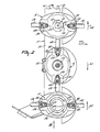
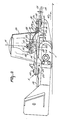
- the mowing arrangement shown in the Figures comprises a mowing bar 1 to which four mowing structures 2, 3, 4 and 5 are fastened.
- the mowing bar 1 is pivotally connected to a carrier arm 6, which is coupled to a fastening trestle 7.
- the fastening trestle 7 includes coupling members 8 and a coupling member 9 by means of which the fastening trestle can be coupled to the lifting arms and to the upper top rod, respectively of a lifting arrangement of a tractor or a suchlike vehicle.
- the mowing bar 1 is made up of a sequence of separate parts comprising separate driving units 12 and intermediate pieces 13.
- the driving units 12 and the intermediate pieces 13 are connected to each other by a tie rod 14.
- the tie rod 14 extends through all of the intermediate pieces 13 and driving units 12.
- the tie rod 14 is heavily loaded in tension, so that all driving units 12 and intermediate pieces 13 are subjected to a compressive force to connect the same together to make up the mowing bar 1.
- the arrangement includes transmission members, not further shown, comprising a coupling shaft 10 which is couplable by means of an intermediate shaft to the power take-off shaft of a tractor or a suchlike vehicle.
- the mowing structures 2, 3, 4 and 5 are coupled to transmission members provided in the driving units 12.
- the transmission members in the driving units 12 are intercoupled by a main driving shaft 40 extending longitudinally to the mowing bar 1 through the driving units 12 and the intermediate pieces 13 in a manner not further shown.
- the driving shaft 40 is coupled via transmission members, not shown, with the coupling shaft 10, so that during operation the mowing members are capable of rotation around upwardly extending rotary axes 11.
- the mowing structures 2 to 5 are of identical construction, which will be further illustrated on the basis of and with reference to mowing structure 5.
- the mowing structure 5 has a carrier 15 which, in a plan view, is in the form of an oval disc.
- the disc-shaped carrier 15 has a conical central portion 16 whose outer circumference, in plan view, is round and passes via folding lines 17 into a, basically flat, peripheral portion 18 which extends perpendicularly to the rotary axis 11.
- the mowing structure 5 comprises two diametrically opposite mowing members 19 and 20.
- the mowing members 19 and 20 are constituted in this embodiment by mowing knives and are both connected in a similar way to the carrier 15, for which reason only the connection of the mowing knife 20 is shown in detail.
- the mowing member 20 is fastened to the bottom side of a supporting member 21.
- the supporting member 21 is bolted to the bottom side of the peripheral portion 18 of the carrier 15 by means of a bolt 22 and a threaded bolt 29, the arrangement being such as is illustrated more specifically in Figure 3.
- the bolt 22 has a bolt head 23, the mowing knife 20 being rotatable around the bolt 22 between the head 23 and the supporting member 21.
- the supporting member 21 has a stop 25 which, taken in a direction of a plane perpendicular to the centre line 26 of the bolt 24, is flush with the mowing member 20.
- the centre line 26 then constitutes a pivotal shaft for the mowing knife 20 arranged rotatably around the bolt 22.
- the supporting member 21 has a portion 26 in the form of a strip, the stop 25 extending downwardly from this strip-shaped portion. In the region of the stop 25 the supporting member 21 has a boss 27 which extends into the extension of the stop 25 and extends over the strip-shaped portion 26. The boss 27 is positioned in an aperture 28 in the carrier 15. The threaded bolt 29 also extends through the aperture 28 and reaches into a threaded hole, not shown, in the boss 27 and the stop 25. The head of the threaded bolt 29 is located above the carrier 15, as is also the nut 24 of the bolt 22.
- the threaded bolt 29 and the bolt 22 extend through apertures in a retaining strip 30 disposed on the upper side of the carrier 15 and extending under the nut 24 and the head of the threaded bolt 29.
- the nut 24 is a self-locking nut and a spring ring 31 is positioned under the head of the threaded bolt 29.
- the peripheral portion 18 is provided with upwardly extending edges 32 and 33 which are formed by outwardly folded portions of the peripheral portion 18.
- the edges 32 and 33 extend, in plan view ( Figure 4), to both sides of the nut 24 and of the head of the bolt 29.
- the edges 32 and 33 have facing sides 34 and 35 which extend at wide angles relative to the flat portion 18 ( Figure 5).
- the sides 36 and 37, which face away from each other, of the edges 32 and 33 are in a considerably flatter position relative to the portion 18.
- the edges 32 and 33 extend from the periphery of the disc-shaped carrier 15 in an approximately radial direction to the conical portion 16.
- edges 32 and 33 are approximately parallel to each other and are slightly bent outwards in the region of the nut 24 around the hole through which the bolt 22 has been inserted. In this situation, flanges 38 and 39 are formed around the nut 24.
- the edges 32 and 33 are at least substantially of the same height as the nut 24 and the head of the threaded bolt 29, respectively.
- the carrier 15 is provided in the peripheral portion 18 with upwardly directed, flanged portions 41 and 42.
- These flanged portions 41 and 42 form so to speak raised peripheral portions 18, the flanging portions 41 and 42 forming recesses at the bottom side of the carrier 15, taken in the direction of the bottom side 43 of the carrier 15.
- These flanged portions 41 and 42 are diametrically opposite to each other and half-way between the mowing members.
- the central section 45 of a carrier is parallel to the bottom side 43 and has an angular, in this embodiment a square, aperture 46.
- the aperture 46 is provided around a boss 47 of a supporting shaft 48, not shown, carrying the mowing structure 5.
- the supporting shaft 48 is bearing-supported in the mowing bar 1 and is connected to the drive members which are contiguous to the coupling shaft 10.
- the central section 45 bears on a supporting edge 49 of the supporting shaft 48.
- the central section 45 and consequently the carrier 15 are pressed down by a pressure member 50.
- the pressure member 50 is positioned around a bolt 51 which is connected to the supporting shaft 48, and is connected to the supporting shaft 48 by means of a nut 44.
- the mowing structures 2, 3 and 4 are connected to a supporting shaft via the respective carriers 15 in a similar way as described in the foregoing for the mowing structure 5.
- the carrier members 15 are so rigid that they have a fairly high resistance against damage. For that purpose they have a thickness 54 of approximately 3 mm, but preferably not exceeding 4 mm.
- the disc-shaped supporting members are preferably made of metal and, in accordance with the invention, preferably of hardened metal.
- the carrier members are in one piece and punched, for example, from one single piece of material.
- Figure 3 shows the mowing structure 5 which constitutes the outermost mowing structure of a row of mowing structures 2 to 5 fastened to the mowing bar 1.
- the mowing structure 5 is disposed on that end of the mowing bar 1 which is remote from the fastening trestle 7 by means of which the mowing arrangement can be coupled to the tractor or a suchlike vehicle.
- a conveyor member for example the conveyor member 56, is preferably connected to such an outermost mowing structure
- the conveyor member 56 is in the form of a conical member which at the same time constitutes a cover member for the fastening means constituted by the pressure member 50 and the nut 54 for connecting the mowing member to the supporting shaft 58.
- the conveyor or cover member is bolted to the carrier 15 by means of the threaded bolts 29.
- these threaded bolts are inserted through holes in lugs 57 which are fastened diametrically opposite to each other to the cover member 56.
- the cover member 56 further bears against the pressure member 40 via a disc 58 which is disposed at the interior side of the cover member 56, the interior side of this disc bearing on an upper edge 59 of the pressure member 50.
- the arrangement is coupled to a tractor or a suchlike vehicle to be moved over the land to be mown.
- the coupling members 8 and 9 can be coupled to the lifting arrangement of the tractor.
- the coupling shaft 10 is coupled to the power take-off shaft of the tractor by means of an intermediate shaft. From the power take-off shaft of the tractor the mowing structures can be caused to rotate via the coupling shaft 10 and the transmission members, not shown, present in the arrangement, in the desired directions of rotation, for example the directions denoted by the arrows 61 and 62 in Figures 1 and 2.
- the crop with which the mowing structures come into contact is cut by the mowing members 19 and 20 rotating around the rotary axes.
- the cut crop is seized by the mowing structures and, partly as a result of the rotation thereof, is conveyed to behind the mowing bar 1.
- the carrier members 15 of the mowing members will catch the crop at least partly, and convey same.
- the mowing structures tend to convey the crop to the rear in those places where they move rearwards. Particularly with large quantities of crop, a large portion thereof will move to the rear over and beyond the mowing structures because of the travel of the arrangement.
- edges 32 and 33 constitute edges to protect the fastening members 22 and 29 from damage and from wear.
- the carrier members are made of hardened metal. This reduces wear of the carrier members. Furthermore this may render the upper surface plane of the carrier to be more appropriate for conveying the crop across and/or through the carriers.
- the edges 32 and 33 fit as tightly as possible around the nut 24 and the head of the threaded bolt 29.
- the sides 34 and 35 of the upwardly flanged edges 32 and 33 are positioned almost vertically or at a large angle relative to the bottom side 43. The sides are in a flatter position than the sides 34 and 35 to provide that the crop will not adhere to the edges 32 and 33.
- the upright edges 32 and 33 will nevertheless be able to provide in an advantageous manner conveyance of the crop.
- the carrier members 15 are preferably punched from one single piece of metal, the edges 32 and 33 being formed as upwardly flanging projections of the disc.
- the carrier members are provided in the region of the mowing members with upwardly directed, flanged projections 41 and 42.
- the mowing members can move beneath the adjacent mowing structures when passing the place where the mowing structures face each other and are located closely adjacently to each other.
- punching the carrier members 15 as one whole they are cheap in production. Because of the fact that the carrier members in the form of a disc are hardened and because of their thickness 54 of approximately 3 mm, these carrier members 15 are highly resistant to wear, for example they are highly resistant to damage caused by hitting on larger or smaller-sized obstacles, such as stones in the field.
- the mowing structures are easy to produce, since the mowing members together with the supporting members 21 can be bolted to the carrier members 15 by means of the bolts 22 and 29: so no members need to be welded to the carrier members 15. Connecting the mowing structures to the carrier shaft 48 via the pressure member 50 and the nut 48 is also easy to realize.
- the nut 54 is fitted to the pin 51 by means of locking means, so that loosening of the nut 54 is hardly possible.
- the mowing structure 5 provided at the end of the row of mowing structures is provided with a cover member in the form of a conveyor member, which more specifically has for its object to keep the mown crop clear from the adjacent crop to be mown in the subsequent run.
- the conveyor member 56 can be easily fastened to the mowing structures by means of the bolts 29, so that no special fastening means for the conveyor member 56 are required.
- a hardened metal carrier it is useful to arrange a retaining strip 30 of a softer material under the spring ring 31 and the nut 24, so that the spring ring and the nut adequately grip the strip to prevent loosening.
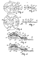
- FIG. 1 and 2 the carrier members 15 are shown to be of an oval shape, it is alternatively possible to use the construction shown for the mowing structures 2 to 5 with round carrier members, as shown in the Figures 6 and 7.
- Figures 6 and 7 illustrate only the differently constructed carrier member 66 of the mowing structures.
- the carrier member 66 of Figures 6 and 7 is provided in a similar way as the carrier member 15 in the preceding embodiment with upwardly directed, flanged edges positioned around the fastening members for the mowing members, so that all this is not shown in greater detail here.
- the central section and the centre portion of the mowing structure are also identical to the mowing member 5. Therefore, identical shapes have been given the same reference numerals as in the preceding embo diment.
- the round shape of the carrier member 66 with respect to the oval disc 15 is obtained, since in the region of the flanged portions 41 and 42 which, compared to the carrier member 15 are directed upwardly, the carrier member 66 is of a greater width.
- the carrier member 66 has upwardly directed, flanged portions 67 and 68 which near the periphery of the central section 16 are equal to the shape of the flanged projections 41 and 42.
- the flanged projections 67 and 68 have an increasing width towards the periphery because the folding lines 69 converge outwardly in a direction away from the centre line 70 of the disc, the arrangement being as shown more specifically in Figure 6.
- the carrier members 66 as are also the carrier members 15, are punched from one single, hardened metal plate and have a thickness equal to the thickness 54 of the carrier member 15.
- the carriers 15 and 16 can be pressed by means of the same dies, as the oval carriers are identical to the carriers 66, but, in the regions of the flanged portions 41 and 42, are shortened so as to provide carriers which are oval compared to the round carriers 66.
- FIG 8 is a vertical cross-sectional view through part of a mowing structure 72 which is in substance identical to the mowing structures 2, 3 and 4. Corresponding components are given the same reference numerals and will not be described in greater detail.
- the respective carrier members 15 and 66 are connected to the bolt 51 by means of a pressure member 73, which pressure member is of a slightly different shape from that of the pressure member 50.
- the pressure member 73 has a slightly conical outer periphery 74. This conical portion 74 of the pressure member 73 is more effective when the mowing structure is not provided at its upper side with a cover member, for example the conveyor member 56.
- the pressure members 73 are therefore preferably used for the mowing structures 2, 3 and 4.
- the conical outer periphery is the cause that crop will not adhere so easily to the pressure member 73.
- the crop moving across the mowing structures and conveyed thereby will consequently move more easily along the conical outer periphery 74.
- the pressure member 73 can, in a similar way as the pressure member 50, press the centre portion 45 against the supporting edge 49.
- an O-ring 75 is additionally arranged between the lower edge of the pressure member 73 and the supporting edge 49.
- This O-ring is slightly resilient, so that the carrier member 15 is capable of some movement between the pressure member 73 and the edge 79. Because of this spring motion of the carrier relative to the carrier shaft 48, shocks which are produced when the mowing structure hits on hard objects, such as stones, can be absorbed. Thus damage to the arrangement will be prevented. Because of the presence of the O-ring 75, there is also obtained a good settlement between the pressure member 73 and the nut 54.
- the central intermediate section of the mowing structures not located at the end of the row may be provided with a lower conical cover cap 76, as is shown in Figure 8.
- This cover cap 76 is round and has an outer periphery which is about equal to the largest diameter of the conical central section 16. At its outer periphery the cover member 76 has projecting lugs 77, so that the cover member 76 can be bolted to the respective carrier members 15 and 66 by means of the bolts 29.
- the mowing structure 72 can be used in a similar manner as the mowing structures 2 to 5 with a mowing arrangement as shown in Figure 1.
- the outermost mowing structure of a row of mowing structures can, as can also the mowing structure 5, be provided with a higher cover member or conveyor member 56, respectively.
- the pressure member for connecting the carrier to the carrier shaft may be of a construction identical to that of the pressure member 50 with a supporting edge 59 for supporting the disc 58.
- Figure 9 shows a vertical cross-sectional view through an embodiment of part of a mowing structure 79, which basically may be identical again to the mowing structures 2 to 5, having an oval carrier 15 or a round carrier 66, respectively.
- the pressure member 80 for connection of the central section of the carrier is of a different construction than in the preceding embodiments.
- the pressure member 80 corresponds to the pressure member 73 but it is of a higher construction, more specifically such that the nut 54 and the bolt 51 are surrounded almost completely by the upwardly extending portions of the presssure member whose outer periphery 81, as is also the outer periphery of the pressure member 73, is of a conical shape.
- the hollow space 82 at the lower side of the pressure member 80 includes a Belleville washer 83 which urges the central section 45 of the carrier member 15 and the carrier member 66, respectively, against the lower supporting edge 49.
- the carrier member 15 is consequently capable of slight movement relative to the carrier shaft 48, whereas the pressure member 80 is pressed against the lower side of the nut 54 to obtain a good position between the member 80 and the nut 54.
- the higher pressure member 80 has as its advantage that the nut 54 and the bolt 51 are less vulnerable to wear by crop moving thereacross. In addition, the higher pressure member 80 will guide the crop such that there is less risk of crop sticking to the bolt 51 or the nut 54.
- a pressure member as shown in Figure 3 can bear in the same way as the pressure members shown in the Figures 8 and 9 against the central section 55 of the carrier member via a spring member, such as an O-ring or a Belleville washer, in order to render possible a small degree of mobility of the mowing structure relative to the carrier shaft 48.
- a spring member such as an O-ring or a Belleville washer
Landscapes
- Life Sciences & Earth Sciences (AREA)
- Environmental Sciences (AREA)
- Harvester Elements (AREA)
Applications Claiming Priority (2)
| Application Number | Priority Date | Filing Date | Title |
|---|---|---|---|
| NL8502803A NL8502803A (nl) | 1985-10-14 | 1985-10-14 | Inrichting en werkwijze voor het maaien van te velde staand gewas. |
| NL8502803 | 1985-10-14 |
Publications (2)
| Publication Number | Publication Date |
|---|---|
| EP0219904A1 true EP0219904A1 (fr) | 1987-04-29 |
| EP0219904B1 EP0219904B1 (fr) | 1995-04-05 |
Family
ID=19846714
Family Applications (1)
| Application Number | Title | Priority Date | Filing Date |
|---|---|---|---|
| EP19860201748 Expired - Lifetime EP0219904B1 (fr) | 1985-10-14 | 1986-10-09 | Dispositif et procédé de fauchage de végétaux |
Country Status (3)
| Country | Link |
|---|---|
| EP (1) | EP0219904B1 (fr) |
| DE (1) | DE3650290T2 (fr) |
| NL (1) | NL8502803A (fr) |
Cited By (4)
| Publication number | Priority date | Publication date | Assignee | Title |
|---|---|---|---|---|
| FR2630289A1 (fr) * | 1988-04-20 | 1989-10-27 | Kuhn Sa | Groupe faucheur dont les outils de coupe sont lies a leur organe de coupe par un dispositif de liaison a axe et ressort a lame et machine de fauchage utilisant un tel groupe faucheur |
| FR2756135A1 (fr) * | 1996-11-26 | 1998-05-29 | Agram | Disque de faucheuse et de faucheuse-conditionneuse |
| EP1145615A1 (fr) * | 2000-04-13 | 2001-10-17 | Maschinenfabrik Bernard Krone GmbH | Faucheuse |
| WO2013108005A1 (fr) * | 2012-01-18 | 2013-07-25 | Spread-A-Bale Limited | Appareil de manipulation de balle |
Families Citing this family (2)
| Publication number | Priority date | Publication date | Assignee | Title |
|---|---|---|---|---|
| JP6129230B2 (ja) * | 2015-03-27 | 2017-05-17 | 本田技研工業株式会社 | 芝刈機 |
| AT525208B1 (de) * | 2021-06-24 | 2023-02-15 | Gebrueder Busatis Ges M B H | Verschleißschutzvorrichtung für Mähscheiben für Rotormähwerke |
Citations (4)
| Publication number | Priority date | Publication date | Assignee | Title |
|---|---|---|---|---|
| FR2248771A1 (en) * | 1973-10-30 | 1975-05-23 | Victa Ltd | Pivotted blade assemblies for rotary mowers - has blade holder formed as truncated cone with depressed diametral portion |
| GB2126067A (en) * | 1982-09-06 | 1984-03-21 | Lely Nv C Van Der | A mowing machine |
| FR2557418A1 (fr) * | 1984-01-04 | 1985-07-05 | Lely Nv C Van Der | Faucheuse |
| FR2561488A1 (fr) * | 1984-03-23 | 1985-09-27 | Sperry Corp | Appareil elevateur de recolte pour faucheuse-conditionneuse a disques |
-
1985
- 1985-10-14 NL NL8502803A patent/NL8502803A/nl active Search and Examination
-
1986
- 1986-10-09 DE DE19863650290 patent/DE3650290T2/de not_active Expired - Fee Related
- 1986-10-09 EP EP19860201748 patent/EP0219904B1/fr not_active Expired - Lifetime
Patent Citations (4)
| Publication number | Priority date | Publication date | Assignee | Title |
|---|---|---|---|---|
| FR2248771A1 (en) * | 1973-10-30 | 1975-05-23 | Victa Ltd | Pivotted blade assemblies for rotary mowers - has blade holder formed as truncated cone with depressed diametral portion |
| GB2126067A (en) * | 1982-09-06 | 1984-03-21 | Lely Nv C Van Der | A mowing machine |
| FR2557418A1 (fr) * | 1984-01-04 | 1985-07-05 | Lely Nv C Van Der | Faucheuse |
| FR2561488A1 (fr) * | 1984-03-23 | 1985-09-27 | Sperry Corp | Appareil elevateur de recolte pour faucheuse-conditionneuse a disques |
Cited By (4)
| Publication number | Priority date | Publication date | Assignee | Title |
|---|---|---|---|---|
| FR2630289A1 (fr) * | 1988-04-20 | 1989-10-27 | Kuhn Sa | Groupe faucheur dont les outils de coupe sont lies a leur organe de coupe par un dispositif de liaison a axe et ressort a lame et machine de fauchage utilisant un tel groupe faucheur |
| FR2756135A1 (fr) * | 1996-11-26 | 1998-05-29 | Agram | Disque de faucheuse et de faucheuse-conditionneuse |
| EP1145615A1 (fr) * | 2000-04-13 | 2001-10-17 | Maschinenfabrik Bernard Krone GmbH | Faucheuse |
| WO2013108005A1 (fr) * | 2012-01-18 | 2013-07-25 | Spread-A-Bale Limited | Appareil de manipulation de balle |
Also Published As
| Publication number | Publication date |
|---|---|
| NL8502803A (nl) | 1987-05-04 |
| EP0219904B1 (fr) | 1995-04-05 |
| DE3650290T2 (de) | 1995-11-09 |
| DE3650290D1 (de) | 1995-05-11 |
Similar Documents
| Publication | Publication Date | Title |
|---|---|---|
| US5725057A (en) | Device for crushing stubble | |
| US8510959B2 (en) | Quick-change disc mower knives | |
| US4189904A (en) | Leaf mulcher attachment for lawn mowers | |
| GB2111364A (en) | Crop mowing devices | |
| US6829878B1 (en) | Quick change disc knife mounting mechanism | |
| EP0219904A1 (fr) | Dispositif et procédé de fauchage de végétaux | |
| DE2418210A1 (de) | Landmaschine, insbesondere fuer die heuernte | |
| US20030110752A1 (en) | Guard for crop pick up apparatus | |
| US3959955A (en) | Self cleaning rotary lawn mower blade and deck assembly | |
| US20130076103A1 (en) | Support wheel assembly for a pick-up of an agricultural machine | |
| KR102093109B1 (ko) | 포크레인에 장착되는 제초기 | |
| US8141651B1 (en) | Thatch rake with flexible thatching assembly | |
| EP1353544B1 (fr) | Dispositif de coupe et de transport pour une barre de coupe travaillant independamment des lignes | |
| US4658910A (en) | Garden tiller plow tine assembly | |
| US4329837A (en) | Agricultural implement for working crop lying on the field | |
| GB1601565A (en) | Crop working machine | |
| US5875855A (en) | Row crop rolling shield | |
| US6305153B1 (en) | Cutting member for agricultural mower | |
| EP0305016A1 (fr) | Dispositif pour le traitement de récolte | |
| EP0806134B1 (fr) | Moissonneuse-batteuse équipée d'un hache-paille | |
| EP2894961B1 (fr) | Andaineuse à bâti d'andainage simple ou double | |
| EP0304120B1 (fr) | Machine pour le travail du sol | |
| JP3539936B2 (ja) | カルチベータ等に取り付ける除草装置 | |
| JPH0350672Y2 (fr) | ||
| US20230031713A1 (en) | Mulcher |
Legal Events
| Date | Code | Title | Description |
|---|---|---|---|
| PUAI | Public reference made under article 153(3) epc to a published international application that has entered the european phase |
Free format text: ORIGINAL CODE: 0009012 |
|
| AK | Designated contracting states |
Kind code of ref document: A1 Designated state(s): DE FR GB NL |
|
| 17P | Request for examination filed |
Effective date: 19870923 |
|
| 17Q | First examination report despatched |
Effective date: 19890720 |
|
| GRAA | (expected) grant |
Free format text: ORIGINAL CODE: 0009210 |
|
| AK | Designated contracting states |
Kind code of ref document: B1 Designated state(s): DE FR GB NL |
|
| REF | Corresponds to: |
Ref document number: 3650290 Country of ref document: DE Date of ref document: 19950511 |
|
| ET | Fr: translation filed | ||
| PGFP | Annual fee paid to national office [announced via postgrant information from national office to epo] |
Ref country code: GB Payment date: 19950926 Year of fee payment: 10 |
|
| PLBE | No opposition filed within time limit |
Free format text: ORIGINAL CODE: 0009261 |
|
| STAA | Information on the status of an ep patent application or granted ep patent |
Free format text: STATUS: NO OPPOSITION FILED WITHIN TIME LIMIT |
|
| 26N | No opposition filed | ||
| PG25 | Lapsed in a contracting state [announced via postgrant information from national office to epo] |
Ref country code: GB Effective date: 19961009 |
|
| GBPC | Gb: european patent ceased through non-payment of renewal fee |
Effective date: 19961009 |
|
| PGFP | Annual fee paid to national office [announced via postgrant information from national office to epo] |
Ref country code: NL Payment date: 20030919 Year of fee payment: 18 |
|
| PGFP | Annual fee paid to national office [announced via postgrant information from national office to epo] |
Ref country code: FR Payment date: 20031020 Year of fee payment: 18 |
|
| PGFP | Annual fee paid to national office [announced via postgrant information from national office to epo] |
Ref country code: DE Payment date: 20031201 Year of fee payment: 18 |
|
| PG25 | Lapsed in a contracting state [announced via postgrant information from national office to epo] |
Ref country code: NL Free format text: LAPSE BECAUSE OF NON-PAYMENT OF DUE FEES Effective date: 20050501 |
|
| PG25 | Lapsed in a contracting state [announced via postgrant information from national office to epo] |
Ref country code: DE Free format text: LAPSE BECAUSE OF NON-PAYMENT OF DUE FEES Effective date: 20050503 |
|
| PG25 | Lapsed in a contracting state [announced via postgrant information from national office to epo] |
Ref country code: FR Free format text: LAPSE BECAUSE OF NON-PAYMENT OF DUE FEES Effective date: 20050630 |
|
| NLV4 | Nl: lapsed or anulled due to non-payment of the annual fee |
Effective date: 20050501 |
|
| REG | Reference to a national code |
Ref country code: FR Ref legal event code: ST |