EP0219335B1 - Artificial knee - Google Patents
Artificial knee Download PDFInfo
- Publication number
- EP0219335B1 EP0219335B1 EP86307895A EP86307895A EP0219335B1 EP 0219335 B1 EP0219335 B1 EP 0219335B1 EP 86307895 A EP86307895 A EP 86307895A EP 86307895 A EP86307895 A EP 86307895A EP 0219335 B1 EP0219335 B1 EP 0219335B1
- Authority
- EP
- European Patent Office
- Prior art keywords
- joint
- blade
- joint according
- medial
- release
- Prior art date
- Legal status (The legal status is an assumption and is not a legal conclusion. Google has not performed a legal analysis and makes no representation as to the accuracy of the status listed.)
- Expired
Links
- 210000003127 knee Anatomy 0.000 title description 9
- 210000000629 knee joint Anatomy 0.000 claims description 18
- 210000002414 leg Anatomy 0.000 claims description 12
- 230000006835 compression Effects 0.000 claims description 5
- 238000007906 compression Methods 0.000 claims description 5
- 239000000463 material Substances 0.000 claims description 5
- 239000013536 elastomeric material Substances 0.000 claims description 3
- 230000002917 arthritic effect Effects 0.000 description 3
- OKTJSMMVPCPJKN-UHFFFAOYSA-N Carbon Chemical compound [C] OKTJSMMVPCPJKN-UHFFFAOYSA-N 0.000 description 2
- 229910052799 carbon Inorganic materials 0.000 description 2
- 239000000835 fiber Substances 0.000 description 2
- 239000006260 foam Substances 0.000 description 2
- 239000002184 metal Substances 0.000 description 2
- 230000000712 assembly Effects 0.000 description 1
- 238000000429 assembly Methods 0.000 description 1
- 230000003139 buffering effect Effects 0.000 description 1
- 239000002537 cosmetic Substances 0.000 description 1
- 239000004033 plastic Substances 0.000 description 1
- 229920003023 plastic Polymers 0.000 description 1
- 230000002441 reversible effect Effects 0.000 description 1
Images



Classifications
-
- A—HUMAN NECESSITIES
- A61—MEDICAL OR VETERINARY SCIENCE; HYGIENE
- A61F—FILTERS IMPLANTABLE INTO BLOOD VESSELS; PROSTHESES; DEVICES PROVIDING PATENCY TO, OR PREVENTING COLLAPSING OF, TUBULAR STRUCTURES OF THE BODY, e.g. STENTS; ORTHOPAEDIC, NURSING OR CONTRACEPTIVE DEVICES; FOMENTATION; TREATMENT OR PROTECTION OF EYES OR EARS; BANDAGES, DRESSINGS OR ABSORBENT PADS; FIRST-AID KITS
- A61F2/00—Filters implantable into blood vessels; Prostheses, i.e. artificial substitutes or replacements for parts of the body; Appliances for connecting them with the body; Devices providing patency to, or preventing collapsing of, tubular structures of the body, e.g. stents
- A61F2/50—Prostheses not implantable in the body
- A61F2/60—Artificial legs or feet or parts thereof
- A61F2/604—Joints for artificial legs
-
- A—HUMAN NECESSITIES
- A61—MEDICAL OR VETERINARY SCIENCE; HYGIENE
- A61F—FILTERS IMPLANTABLE INTO BLOOD VESSELS; PROSTHESES; DEVICES PROVIDING PATENCY TO, OR PREVENTING COLLAPSING OF, TUBULAR STRUCTURES OF THE BODY, e.g. STENTS; ORTHOPAEDIC, NURSING OR CONTRACEPTIVE DEVICES; FOMENTATION; TREATMENT OR PROTECTION OF EYES OR EARS; BANDAGES, DRESSINGS OR ABSORBENT PADS; FIRST-AID KITS
- A61F2/00—Filters implantable into blood vessels; Prostheses, i.e. artificial substitutes or replacements for parts of the body; Appliances for connecting them with the body; Devices providing patency to, or preventing collapsing of, tubular structures of the body, e.g. stents
- A61F2/50—Prostheses not implantable in the body
- A61F2/60—Artificial legs or feet or parts thereof
- A61F2/64—Knee joints
-
- A—HUMAN NECESSITIES
- A61—MEDICAL OR VETERINARY SCIENCE; HYGIENE
- A61F—FILTERS IMPLANTABLE INTO BLOOD VESSELS; PROSTHESES; DEVICES PROVIDING PATENCY TO, OR PREVENTING COLLAPSING OF, TUBULAR STRUCTURES OF THE BODY, e.g. STENTS; ORTHOPAEDIC, NURSING OR CONTRACEPTIVE DEVICES; FOMENTATION; TREATMENT OR PROTECTION OF EYES OR EARS; BANDAGES, DRESSINGS OR ABSORBENT PADS; FIRST-AID KITS
- A61F2/00—Filters implantable into blood vessels; Prostheses, i.e. artificial substitutes or replacements for parts of the body; Appliances for connecting them with the body; Devices providing patency to, or preventing collapsing of, tubular structures of the body, e.g. stents
- A61F2/50—Prostheses not implantable in the body
- A61F2002/5007—Prostheses not implantable in the body having elastic means different from springs, e.g. including an elastomeric insert
-
- A—HUMAN NECESSITIES
- A61—MEDICAL OR VETERINARY SCIENCE; HYGIENE
- A61F—FILTERS IMPLANTABLE INTO BLOOD VESSELS; PROSTHESES; DEVICES PROVIDING PATENCY TO, OR PREVENTING COLLAPSING OF, TUBULAR STRUCTURES OF THE BODY, e.g. STENTS; ORTHOPAEDIC, NURSING OR CONTRACEPTIVE DEVICES; FOMENTATION; TREATMENT OR PROTECTION OF EYES OR EARS; BANDAGES, DRESSINGS OR ABSORBENT PADS; FIRST-AID KITS
- A61F2/00—Filters implantable into blood vessels; Prostheses, i.e. artificial substitutes or replacements for parts of the body; Appliances for connecting them with the body; Devices providing patency to, or preventing collapsing of, tubular structures of the body, e.g. stents
- A61F2/50—Prostheses not implantable in the body
- A61F2002/5038—Hinged joint, e.g. with transverse axle restricting the movement
- A61F2002/5043—Hinged joint, e.g. with transverse axle restricting the movement with rotation-limiting stops, e.g. projections or recesses
-
- A—HUMAN NECESSITIES
- A61—MEDICAL OR VETERINARY SCIENCE; HYGIENE
- A61F—FILTERS IMPLANTABLE INTO BLOOD VESSELS; PROSTHESES; DEVICES PROVIDING PATENCY TO, OR PREVENTING COLLAPSING OF, TUBULAR STRUCTURES OF THE BODY, e.g. STENTS; ORTHOPAEDIC, NURSING OR CONTRACEPTIVE DEVICES; FOMENTATION; TREATMENT OR PROTECTION OF EYES OR EARS; BANDAGES, DRESSINGS OR ABSORBENT PADS; FIRST-AID KITS
- A61F2/00—Filters implantable into blood vessels; Prostheses, i.e. artificial substitutes or replacements for parts of the body; Appliances for connecting them with the body; Devices providing patency to, or preventing collapsing of, tubular structures of the body, e.g. stents
- A61F2/50—Prostheses not implantable in the body
- A61F2/68—Operating or control means
- A61F2002/6854—Operating or control means for locking or unlocking a joint
Definitions
- This invention relates to a knee joint for a leg prosthesis.
- the terms «vertical» and «horizontal» are general terms to be understood with reference to the attitude of the leg when the user is standing with his knees straight or extended.
- a representative self-locking knee joint of the prior art is shown in Patent Specification No. GB-B-2 099 708 and employs a sliding locking plunger pulled along its vertical line of action by a release cable, an upper member or knee ball being received in a housing forming part of the lower or shin member, and the knee pivot being between bearings to opposed sides of the knee housing.
- a similar joint in which a head of a lower member fits between bifurcations of an upper member with a pin positioned at a posterior location is shown in US-A-4 149 280 and US-A-4 283 800 (Wilson), but there is no provision for locking the joint in extension.
- the invention provides a knee joint for a leg prosthesis, wherein a pin at a posterior location of said joint pivotally interconnects upper and lower members, and a latch member pivoted to one of said members for rotation about a vertical axis releasably locks in a recess in the other of said members to hold the joint in its extended position.
- the upper member preferably has depending medial and lateral portions defining cheeks between which a head of the lower member is received.
- the adjoining horizontal faces of the upper and lower members may be planar, in which case a pad of elastomeric material may be attached to one of said planar surfaces to act as an extension stop buffer.
- the latch member is a generally bell-cranked blade, that fits into slots in the anterior edge of each cheek and is pivoted to one of the cheeks with an anterior lever spanning between the cheeks and having a latch head that fits into said socket and a medial/lateral leveractuated by a cable release.
- the lower member preferably has at an anterior position on its head a nose of wear resistant material that cams the blade to its release position as the joint moves to the extended position, the blade disengaging from the nose as the extended position is reached to snap into the recess.
- the release cable advantageously passes to a posterior portion of the medial/lateral lever through an axial bore in the pin, an enlarged portion of said bore housing a compression coil spring that urges the blade towards its locking position, and the posterior portion of the medial/lateral lever advantageously slides between furcations at an end of the pin during travel of the blade between release and locking positions.
- a socket alignment cup 20 as described in our copending UK patent application No. 8 524 028 is connected through baseplate 21 and optional socket rotator 22 as described in our patent application No. 8 524 028 to an upper knee joint assembly generally indicated by the reference numeral 1.
- the assembly 1 includes a body formed with portions defining a top plate 24 that is a mitered square in plan and has medial and lateral cheek plates 25.
- Each cheek plate 25 is formed with a narrow horizontal slot 26 extending in a posterior direction from the front edge of the plate and with a through-hole for a knee-joint pin 4 in a protruding part hexagonal posterior region 27 thereof.
- a knee joint lower sub-assembly generally indicated by the reference numeral 2 has a depending socket 30 which fits onto the upper end of a shin tube 31.
- the tube 31 which may be of metal or carbon fibre is reinforced by a flanged metal tube slidingly fitted into its blind end, and in the illustrated arrangement which is for a carbon fibre tube the socket 30 is formed with a pinch bolt structure 32 that may be tightened by clamping bolt 33 to retain the tube 31 in the socket 30.
- the lower sub-assembly 2 is formed with an enlarged plate-like head 36 that fits between the cheek plates 25 of the upper knee-joint sub-assembly 1, the posterior portion of the head 36 being semi-circular in side profile and having a transverse bore into which the knee joint pin 4 fits.
- the head has a flat top surface 37 and an anterior cut-out defining a front step 38 bounded by medial and lateral recess or catch-defining cutouts 39 of the same depth as a latch blade 40 that fits into and spans between the slots 26 of the upper assembly 1.
- the top face 37 is formed with medial and lateral downwardly bevelled surfaces 41 over which the blade 40 travels as the joint is unflexed before it engages in the catches or recesses 39.
- a bullet-shaped nose 45 of wear-resistant material that serves to cam the blade 40 to its unlatched position as the joint moves to the extended position, the blade snapping into one of the recesses 39 as the joint reaches its extended position.
- a flat top surface 37 of the head 36 has attached thereto, e.g. by fixing screws, a buffer stop 19 of elastomeric material with optional shim plates beneath it to adjust the heigth of the stop 19 and properly define the unflexed position of the joint.
- the latch blade 40 as best seen in Figure 2 is of bell- crank shape in plan, fits slidingly into the slots 26 and is pivoted adjacent the angulation therein on a pivot screw 10 that fits into a vertical anterior bore 34 in one of the cheek plates 25.
- the head of screw 10 is socketed so that the screw may be tightened by means of an alien key as seen in Figure 2. Accordingly, the horizontally directed blade 40 is pivoted for rotation towards and away from the sockets 39 about a vertical axis defined by the screw 10.
- a tip enlargement of the anterior lever 51 of blade 40 in the posterior direction defines a latch head 50 that engages in one or the other of recesses 39 to hold the joint unflexed.
- the blade 40 is reversible and may be pivoted to either of the cheek plates 25 so that the same parts may be used interchangeably for a left or a right leg.
- a medial lever 52 of the blade 40 fits slidingly between furcations 53 at the medial end of the pin 4.
- the pin 4 is hollow, with a release cable 6 passing through from the lateral end of pin 4, via bore 61 and enlarged counterbore 62 that houses compression spring 9 together with sliding piece 63 that bears against medial lever 52.
- the cable 6 continues through spring 9, piece 63 and medial lever 52 to which the cable 6 is held by an enlarged end-piece 64 and pin 64a.
- the medial lever 52 is reciprocable within the slot between furcations 53 by pulling on release cable 6.
- the outer edge of lever 52 is covered by guard plate 8 that has a rear edge bifurcation 65 to allow passage of the pin 4.
- Circlips 66 between the cheek plates 25 and the pin 4 retain the pin 4 in position in the assembled knee.
- the posterior position of the pin 4 enables high degree of flexion approaching 180°. Because the blade 40 acts as a pair of levers, the release force required in cable 6 and return force to be provided by compression spring 9 can be relatively low compared to prior art knee joints where a release cable pulls along the line of action of a locking plunger and this is an advantage for arthritic or geriatric patients who find it difficult or painful to exert more then a minimal force on a release lever (not shown) connected to the other end of the cable 6.
- the joint is both of low height and compact but is robust and provides for a high degree of flexion. It may fit inside a one-piece leg cosmesis of foamed plastics material without the foam being damaged in service because, as seen in Figure 5, the cheek plates 25 serve to push the material of the cosmesis from the gap between the upper and lower assemblies 1, 2 as the joint is unflexed. It readily provides the manual release/self- locking action appropriate to geriatric or arthritic patients.
Landscapes
- Health & Medical Sciences (AREA)
- Transplantation (AREA)
- Biomedical Technology (AREA)
- Cardiology (AREA)
- Oral & Maxillofacial Surgery (AREA)
- Engineering & Computer Science (AREA)
- Orthopedic Medicine & Surgery (AREA)
- Heart & Thoracic Surgery (AREA)
- Vascular Medicine (AREA)
- Life Sciences & Earth Sciences (AREA)
- Animal Behavior & Ethology (AREA)
- General Health & Medical Sciences (AREA)
- Public Health (AREA)
- Veterinary Medicine (AREA)
- Prostheses (AREA)
Description
- This invention relates to a knee joint for a leg prosthesis. In this specification the terms «vertical» and «horizontal» are general terms to be understood with reference to the attitude of the leg when the user is standing with his knees straight or extended.
- A representative self-locking knee joint of the prior art is shown in Patent Specification No. GB-B-2 099 708 and employs a sliding locking plunger pulled along its vertical line of action by a release cable, an upper member or knee ball being received in a housing forming part of the lower or shin member, and the knee pivot being between bearings to opposed sides of the knee housing. A similar joint in which a head of a lower member fits between bifurcations of an upper member with a pin positioned at a posterior location is shown in US-A-4 149 280 and US-A-4 283 800 (Wilson), but there is no provision for locking the joint in extension.
- It is an object of the invention to provide a knee joint for a leg prosthesis that is of light weight, is compact, is strong and is of low height considered with reference to the longitudinal direction of the leg and gives a large angle of flexion.
- It is a further object of the invention to provide a knee joint for a leg prosthesis that locks and unlocks with low operating forces so that it can be used by elderly and arthritic patients.
- It is a yet further object of the invention to provide a knee joint for a leg prosthesis that when fitted into a cosmesis gives good cosmetic restoration and minimises damage to foam of said cosmesis flowing from repeated flexion and extension of the knee.
- Broadly stated the invention provides a knee joint for a leg prosthesis, wherein a pin at a posterior location of said joint pivotally interconnects upper and lower members, and a latch member pivoted to one of said members for rotation about a vertical axis releasably locks in a recess in the other of said members to hold the joint in its extended position.
- The upper member preferably has depending medial and lateral portions defining cheeks between which a head of the lower member is received. The adjoining horizontal faces of the upper and lower members may be planar, in which case a pad of elastomeric material may be attached to one of said planar surfaces to act as an extension stop buffer. Advantageously the latch member is a generally bell-cranked blade, that fits into slots in the anterior edge of each cheek and is pivoted to one of the cheeks with an anterior lever spanning between the cheeks and having a latch head that fits into said socket and a medial/lateral leveractuated by a cable release. The lower member preferably has at an anterior position on its head a nose of wear resistant material that cams the blade to its release position as the joint moves to the extended position, the blade disengaging from the nose as the extended position is reached to snap into the recess. The release cable advantageously passes to a posterior portion of the medial/lateral lever through an axial bore in the pin, an enlarged portion of said bore housing a compression coil spring that urges the blade towards its locking position, and the posterior portion of the medial/lateral lever advantageously slides between furcations at an end of the pin during travel of the blade between release and locking positions.
- An embodiment of the invention will now be described, by way of example only, with reference to the accompanying drawings, in which:
- Figures 1 and 2 are respectively a front perspective view of a knee joint according to the invention in an upright unflexed position and laid flat in a partly flexed position and partially exploded:
- Figures 3 and 4 are fragmentary side and front views of a knee unit according to the invention in position in an artificial leg:
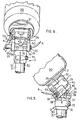
- Figures 5 and 6 are views corresponding to Figures 1 and 2, but with the knee joint flexed; and
- Figures 7 to 10 are respectively a plan of the knee joint, a section on the line A-A of Figure 7, a section on the line B-B of Figure 3 and a section on the line C-C of Figure 4.
- In the drawings, a
socket alignment cup 20 as described in our copending UK patent application No. 8 524 028 is connected throughbaseplate 21 andoptional socket rotator 22 as described in our patent application No. 8 524 028 to an upper knee joint assembly generally indicated by the reference numeral 1. The assembly 1 includes a body formed with portions defining atop plate 24 that is a mitered square in plan and has medial andlateral cheek plates 25. Eachcheek plate 25 is formed with a narrowhorizontal slot 26 extending in a posterior direction from the front edge of the plate and with a through-hole for a knee-joint pin 4 in a protruding part hexagonalposterior region 27 thereof. - A knee joint lower sub-assembly generally indicated by the
reference numeral 2 has a dependingsocket 30 which fits onto the upper end of ashin tube 31. Thetube 31 which may be of metal or carbon fibre is reinforced by a flanged metal tube slidingly fitted into its blind end, and in the illustrated arrangement which is for a carbon fibre tube thesocket 30 is formed with apinch bolt structure 32 that may be tightened by clampingbolt 33 to retain thetube 31 in thesocket 30. Above thesocket 30 thelower sub-assembly 2 is formed with an enlarged plate-like head 36 that fits between thecheek plates 25 of the upper knee-joint sub-assembly 1, the posterior portion of thehead 36 being semi-circular in side profile and having a transverse bore into which theknee joint pin 4 fits. The head has aflat top surface 37 and an anterior cut-out defining afront step 38 bounded by medial and lateral recess or catch-definingcutouts 39 of the same depth as alatch blade 40 that fits into and spans between theslots 26 of the upper assembly 1. Thetop face 37 is formed with medial and lateral downwardlybevelled surfaces 41 over which theblade 40 travels as the joint is unflexed before it engages in the catches orrecesses 39. In the centre of the stepped front face of thehead 36 there is a bullet-shaped nose 45 of wear-resistant material that serves to cam theblade 40 to its unlatched position as the joint moves to the extended position, the blade snapping into one of therecesses 39 as the joint reaches its extended position. Aflat top surface 37 of thehead 36 has attached thereto, e.g. by fixing screws, abuffer stop 19 of elastomeric material with optional shim plates beneath it to adjust the heigth of thestop 19 and properly define the unflexed position of the joint. - The
latch blade 40 as best seen in Figure 2 is of bell- crank shape in plan, fits slidingly into theslots 26 and is pivoted adjacent the angulation therein on apivot screw 10 that fits into a verticalanterior bore 34 in one of thecheek plates 25. The head ofscrew 10 is socketed so that the screw may be tightened by means of an alien key as seen in Figure 2. Accordingly, the horizontally directedblade 40 is pivoted for rotation towards and away from thesockets 39 about a vertical axis defined by thescrew 10. A tip enlargement of theanterior lever 51 ofblade 40 in the posterior direction defines alatch head 50 that engages in one or the other ofrecesses 39 to hold the joint unflexed. It will be appreciated that theblade 40 is reversible and may be pivoted to either of thecheek plates 25 so that the same parts may be used interchangeably for a left or a right leg. Amedial lever 52 of theblade 40 fits slidingly betweenfurcations 53 at the medial end of thepin 4. As seen in Figure 8, thepin 4 is hollow, with arelease cable 6 passing through from the lateral end ofpin 4, via bore 61 and enlargedcounterbore 62 that housescompression spring 9 together with slidingpiece 63 that bears againstmedial lever 52. Thecable 6 continues throughspring 9,piece 63 andmedial lever 52 to which thecable 6 is held by an enlarged end-piece 64 andpin 64a. Accordingly, themedial lever 52 is reciprocable within the slot betweenfurcations 53 by pulling onrelease cable 6. The outer edge oflever 52 is covered byguard plate 8 that has arear edge bifurcation 65 to allow passage of thepin 4. Circlips 66 between thecheek plates 25 and thepin 4 retain thepin 4 in position in the assembled knee. - As the knee joint is moved from the flexed position of Figures 5 and 6 towards the extended position of Figures 3 and 4 the
blade 40 encounters thenose 45 and is rotated so that thelatch head 50 rides over and eventually clears thesurface 41 and as the knee reaches its extended position is snapped bycompression spring 9 into latching engagement withsocket 39 of theshin part 2. Travel to the extended positions of Figures 3 and 4 also compresses thebuffer stop 19 between the lower face ofplate 24 and thetop face 37 ofhead 36, and, as previously stated, shims inserted above thebuffer stop 19 serve to adjust the buffering action as required. Release is effected by pulling oncable 6 which pivots theblade 40 so as to disengagelatch head 50 from therecess 39, after which the joint is free to flex. The posterior position of thepin 4 enables high degree of flexion approaching 180°. Because theblade 40 acts as a pair of levers, the release force required incable 6 and return force to be provided bycompression spring 9 can be relatively low compared to prior art knee joints where a release cable pulls along the line of action of a locking plunger and this is an advantage for arthritic or geriatric patients who find it difficult or painful to exert more then a minimal force on a release lever (not shown) connected to the other end of thecable 6. - It will be noted that the joint is both of low height and compact but is robust and provides for a high degree of flexion. It may fit inside a one-piece leg cosmesis of foamed plastics material without the foam being damaged in service because, as seen in Figure 5, the
cheek plates 25 serve to push the material of the cosmesis from the gap between the upper andlower assemblies 1, 2 as the joint is unflexed. It readily provides the manual release/self- locking action appropriate to geriatric or arthritic patients.
Claims (9)
Applications Claiming Priority (2)
| Application Number | Priority Date | Filing Date | Title |
|---|---|---|---|
| GB858525303A GB8525303D0 (en) | 1985-10-14 | 1985-10-14 | Artificial knee |
| GB8525303 | 1985-10-14 |
Publications (2)
| Publication Number | Publication Date |
|---|---|
| EP0219335A1 EP0219335A1 (en) | 1987-04-22 |
| EP0219335B1 true EP0219335B1 (en) | 1989-11-29 |
Family
ID=10586640
Family Applications (1)
| Application Number | Title | Priority Date | Filing Date |
|---|---|---|---|
| EP86307895A Expired EP0219335B1 (en) | 1985-10-14 | 1986-10-13 | Artificial knee |
Country Status (5)
| Country | Link |
|---|---|
| US (1) | US4756713A (en) |
| EP (1) | EP0219335B1 (en) |
| JP (1) | JPS6287149A (en) |
| DE (1) | DE3667136D1 (en) |
| GB (2) | GB8525303D0 (en) |
Families Citing this family (11)
| Publication number | Priority date | Publication date | Assignee | Title |
|---|---|---|---|---|
| GB8627952D0 (en) * | 1986-11-21 | 1986-12-31 | Hanger & Co Ltd J E | Shift device |
| US5405408A (en) * | 1993-05-14 | 1995-04-11 | Pitkin; Mark R. | Artificial knee having dual flexion action during locomotion |
| US6912737B2 (en) * | 2002-11-22 | 2005-07-05 | Theresa Ernest | Disposable urine collection device |
| US7087090B2 (en) * | 2003-11-19 | 2006-08-08 | Bloorview Macmillan Centre | Artificial knee joint |
| CA2597334C (en) * | 2005-01-17 | 2012-03-20 | Bloorview Macmillan Centre | Artificial knee joint |
| EP2250977B1 (en) | 2008-03-07 | 2014-07-23 | Nabtesco Corporation | Knee joint including manual lock mechanism and artificial thigh |
| US20140188252A1 (en) * | 2011-03-03 | 2014-07-03 | D-Rev: Design For The Other Ninety Percent | Polycentric knee joint prosthesis for extreme affordability |
| USD789616S1 (en) | 2016-06-29 | 2017-06-13 | Tenacious Holdings, Inc. | Knee pad |
| USD788992S1 (en) | 2016-06-29 | 2017-06-06 | Tenacious Holdings, Inc. | Knee pad |
| USD788993S1 (en) | 2016-06-29 | 2017-06-06 | Tenacious Holdings, Inc. | Knee pad |
| USD789617S1 (en) | 2016-06-29 | 2017-06-13 | Tenacious Holdings, Inc. | Knee pad |
Family Cites Families (10)
| Publication number | Priority date | Publication date | Assignee | Title |
|---|---|---|---|---|
| US688936A (en) * | 1901-04-13 | 1901-12-17 | David Devol | Artificial limb. |
| GB185173A (en) * | 1921-05-24 | 1922-08-24 | Frederick Charles Lynde | Improvements in joints for artificial limbs |
| FR543945A (en) * | 1921-11-26 | 1922-09-12 | Kellner Freres | Slack Adjustment Lock Bolt For Body And Other Applications |
| US1661113A (en) * | 1926-03-10 | 1928-02-28 | Deshon Eduardo Rafael | Hinge |
| GB712942A (en) * | 1952-05-28 | 1954-08-04 | William Arthur David Blatchfor | Improvements in artificial legs |
| GB908377A (en) * | 1961-01-25 | 1962-10-17 | France Etat | Improvements in or relating to a leg prosthesis apparatus |
| US3837010A (en) * | 1972-03-16 | 1974-09-24 | Parke Davis & Co | Prosthetic elbow with resilient locking assembly |
| GB1586302A (en) * | 1977-07-08 | 1981-03-18 | Kellie & Son Ltd Robert | Lockable hinge joint for limb supports and other orthopaedic appliances |
| CA1191301A (en) * | 1981-12-07 | 1985-08-06 | Frank M. Lewis | Shock absorbing stop for prosthetic devices |
| DE3414869C2 (en) * | 1984-04-19 | 1986-09-25 | Fa. Wilhelm Julius Teufel, 7000 Stuttgart | Artificial knee joint |
-
1985
- 1985-10-14 GB GB858525303A patent/GB8525303D0/en active Pending
-
1986
- 1986-10-13 GB GB8624464A patent/GB2181357B/en not_active Expired
- 1986-10-13 EP EP86307895A patent/EP0219335B1/en not_active Expired
- 1986-10-13 DE DE8686307895T patent/DE3667136D1/en not_active Expired - Lifetime
- 1986-10-14 JP JP61242183A patent/JPS6287149A/en active Pending
- 1986-10-14 US US06/917,976 patent/US4756713A/en not_active Expired - Fee Related
Also Published As
| Publication number | Publication date |
|---|---|
| EP0219335A1 (en) | 1987-04-22 |
| GB8624464D0 (en) | 1986-11-19 |
| DE3667136D1 (en) | 1990-01-04 |
| GB2181357B (en) | 1989-09-27 |
| GB8525303D0 (en) | 1985-11-20 |
| JPS6287149A (en) | 1987-04-21 |
| GB2181357A (en) | 1987-04-23 |
| US4756713A (en) | 1988-07-12 |
Similar Documents
| Publication | Publication Date | Title |
|---|---|---|
| US4756713A (en) | Artificial knee | |
| EP0529408B1 (en) | Knee endoprosthesis | |
| US4458367A (en) | Knee joint for artificial limbs | |
| EP0545833B1 (en) | Knee prosthesis | |
| EP0957834B1 (en) | Stabilised mobile bearing knee | |
| EP1646335B1 (en) | Mobile bearing knee prosthesis | |
| EP1374805B1 (en) | Modular knee joint prosthesis | |
| EP1852092A1 (en) | Latchable prosthetic joint | |
| EP0852934B1 (en) | Tibial tray for an artificial knee joint | |
| DE69503381T2 (en) | Knee-joint prosthesis | |
| US8062370B2 (en) | Intervertebral prosthesis with a limit stop plate | |
| US5690637A (en) | Guide for patellar cuts | |
| DE69009509T2 (en) | Modular knee prosthesis system. | |
| DE69328690T2 (en) | FULL KNEE PROSTHESIS | |
| EP0016268B1 (en) | Lockable hinge joint for limb supports and other orthopaedic appliances | |
| EP0627203A2 (en) | Prosthetic joint | |
| US20050089363A1 (en) | Device for offsetting prosthetic components | |
| IE41751B1 (en) | Prosthetic knee joints | |
| US7267695B2 (en) | Four hole offset alignment device | |
| WO2019228769A1 (en) | Upper leg prosthesis adapter | |
| EP1707157A1 (en) | Femoral prosthetic component | |
| EP2345391A1 (en) | Knee prosthetic | |
| EP0547118B1 (en) | An artificial joint mechanism for use in reconstructing joints | |
| GB2338899A (en) | Connector for orthoses or prostheses | |
| EP0095872A1 (en) | Improvements in or relating to knee joints for artificial legs |
Legal Events
| Date | Code | Title | Description |
|---|---|---|---|
| PUAI | Public reference made under article 153(3) epc to a published international application that has entered the european phase |
Free format text: ORIGINAL CODE: 0009012 |
|
| AK | Designated contracting states |
Kind code of ref document: A1 Designated state(s): DE FR |
|
| 17P | Request for examination filed |
Effective date: 19870903 |
|
| 17Q | First examination report despatched |
Effective date: 19890308 |
|
| GRAA | (expected) grant |
Free format text: ORIGINAL CODE: 0009210 |
|
| AK | Designated contracting states |
Kind code of ref document: B1 Designated state(s): DE FR |
|
| REF | Corresponds to: |
Ref document number: 3667136 Country of ref document: DE Date of ref document: 19900104 |
|
| ET | Fr: translation filed | ||
| PLBE | No opposition filed within time limit |
Free format text: ORIGINAL CODE: 0009261 |
|
| PLBE | No opposition filed within time limit |
Free format text: ORIGINAL CODE: 0009261 |
|
| STAA | Information on the status of an ep patent application or granted ep patent |
Free format text: STATUS: NO OPPOSITION FILED WITHIN TIME LIMIT |
|
| 26N | No opposition filed | ||
| 26N | No opposition filed | ||
| PGFP | Annual fee paid to national office [announced via postgrant information from national office to epo] |
Ref country code: FR Payment date: 19910822 Year of fee payment: 6 |
|
| PGFP | Annual fee paid to national office [announced via postgrant information from national office to epo] |
Ref country code: DE Payment date: 19911231 Year of fee payment: 6 |
|
| PG25 | Lapsed in a contracting state [announced via postgrant information from national office to epo] |
Ref country code: FR Effective date: 19930630 |
|
| PG25 | Lapsed in a contracting state [announced via postgrant information from national office to epo] |
Ref country code: DE Effective date: 19930701 |
|
| REG | Reference to a national code |
Ref country code: FR Ref legal event code: ST |