EP0219178A2 - Verfahren zur Entfernung flüchtiger Stoffe aus einer Flüssigkeit und Vorrichtung zur Durchführung dieses Verfahrens - Google Patents
Verfahren zur Entfernung flüchtiger Stoffe aus einer Flüssigkeit und Vorrichtung zur Durchführung dieses Verfahrens Download PDFInfo
- Publication number
- EP0219178A2 EP0219178A2 EP86201794A EP86201794A EP0219178A2 EP 0219178 A2 EP0219178 A2 EP 0219178A2 EP 86201794 A EP86201794 A EP 86201794A EP 86201794 A EP86201794 A EP 86201794A EP 0219178 A2 EP0219178 A2 EP 0219178A2
- Authority
- EP
- European Patent Office
- Prior art keywords
- liquid
- chamber
- imposed
- installation
- vapor
- Prior art date
- Legal status (The legal status is an assumption and is not a legal conclusion. Google has not performed a legal analysis and makes no representation as to the accuracy of the status listed.)
- Granted
Links
Images
Classifications
-
- C—CHEMISTRY; METALLURGY
- C11—ANIMAL OR VEGETABLE OILS, FATS, FATTY SUBSTANCES OR WAXES; FATTY ACIDS THEREFROM; DETERGENTS; CANDLES
- C11B—PRODUCING, e.g. BY PRESSING RAW MATERIALS OR BY EXTRACTION FROM WASTE MATERIALS, REFINING OR PRESERVING FATS, FATTY SUBSTANCES, e.g. LANOLIN, FATTY OILS OR WAXES; ESSENTIAL OILS; PERFUMES
- C11B3/00—Refining fats or fatty oils
- C11B3/12—Refining fats or fatty oils by distillation
- C11B3/14—Refining fats or fatty oils by distillation with the use of indifferent gases or vapours, e.g. steam
-
- B—PERFORMING OPERATIONS; TRANSPORTING
- B01—PHYSICAL OR CHEMICAL PROCESSES OR APPARATUS IN GENERAL
- B01D—SEPARATION
- B01D19/00—Degasification of liquids
- B01D19/0005—Degasification of liquids with one or more auxiliary substances
- B01D19/001—Degasification of liquids with one or more auxiliary substances by bubbling steam through the liquid
- B01D19/0015—Degasification of liquids with one or more auxiliary substances by bubbling steam through the liquid in contact columns containing plates, grids or other filling elements
Definitions
- the present invention relates to a process for removing a volatile material from a liquid according to which a constant translation is applied to the liquid at low absolute pressure while passing vapor through the liquid which takes up material volatile.
- Typical examples of such a process are the deodorization and deacidification of vegetable and animal oils and fats.
- Oil or fat is the liquid.
- the volatile matter is constituted by odoriferous materials or by free fatty acids and said vapor is water vapor.
- Unwanted volatiles to be removed have a very low vapor pressure. Therefore their evaporation can only be accomplished at very low absolute pressures, of the order of 3 to 5 millibars, and at temperatures of the order of 180 ° C to 260 ° C.
- the water vapor injected into the mass of the oil or fat reduces the partial pressure of the vapor of the volatile matter present, which can thus be entrained in the water vapor.
- the temperature at which edible oils and fats can be processed is limited by the fact that excessive heating of a fat causes hydrolysis of the glycerides.
- the duration of the treatment the quantity of water vapor to be injected and thereby the consumption of steam should be as low as possible.
- the vapor / liquid contact must therefore be as perfect and complete as possible.
- live steam must be systematically distributed in the mass of liquid so that it is saturated with volatile matter before escaping from the surface of the liquid.
- the vapor bubbles distributed in the mass of the oil or fat being treated are loaded with volatile matter and rise to the surface.
- the vaporization efficiency (E) is defined as the ratio between the actual partial pressure of the volatile in the rising vapor bubbles (Pvv) and the partial pressure of the volatile which would be in equilibrium in the same place in the fat (Pvg).
- the treated oil layer must be shallow and in practice this, depending on the devices used, is min. 20 cm and max. 1.2 m, for efficient steam brewing.
- the stirring of the mass of oil or fat with live steam takes place during the continuous displacement of this mass in the deacidification and / or deodorization apparatus.
- the duration of treatment is not the same for all the particles of the liquid, that which underwent the shortest treatment will indisputably determine the degree of deacidification and / or deodorization of all the fat.
- the average duration of the treatment that has been adopted is a predominant characteristic.
- Continuous treatment processes thus require complicated devices whose volume often exceeds 30% the volume of a device of the same capacity which would carry out a homogeneous treatment for all the product treated.
- the object of the invention is to remedy this drawback and to provide a continuous and all the same homogeneous treatment process which can be carried out in a relatively simple device with a minimum of steam and at a temperature low enough to avoid hydrolysis.
- the liquid for example oil or fat
- the liquid is fully subjected to the ideal conditions for the distillation of volatile compounds, since the freshly admitted liquid is immediately uniformly distributed over the surface of the liquid present, namely at the zone where the evaporation conditions are most favorable and this by the low pressure prevailing there; there is indeed no hydrostatic pressure on this surface.
- Steam is preferably introduced into the lower part of the liquid over the entire lower section of the latter.
- the vapor thus rises in the form of bubbles to the free surface of the liquid. These bubbles act effectively and completely as a vapor for entraining volatile matter. These bubbles cover all the particles of the liquid to be treated.
- said slow, vertical translation from top to bottom is imposed on the liquid at a speed of less than 1 cm / sec. .
- the invention also relates to an installation intended for the implementation of the method defined above.
- the invention relates to an installation for removing volatile matter from a liquid by means of a vapor comprising - at least one chamber intended for the liquid, - a liquid supply pipe opening into the upper part of the chamber, - a liquid evacuation pipe from the lower part of the chamber, means for introducing steam into the chamber, and - a passage for the evacuation of gas from the upper part of the chamber.
- This known installation is obviously intended for the discontinuous treatment of the liquid (oil and material oily).
- the vapor is introduced in the middle of the section of the chamber over a large part of its height and causes a turbulent and rapid movement of the liquid and the vapor conditioned in particular by a rather complicated arrangement of plates.
- the installation according to the invention on the contrary is intended for a treatment in which the liquid undergoes only a slow translation from top to bottom, the vapor being introduced only at the lower part of the liquid over the entire section of the latter and rising in the form bubbles to the surface of the liquid where these bubbles form a foam receiving the freshly admitted liquid.
- the steam introduction means open in the immediate vicinity of the bottom of the chamber and the chamber is, over its entire height, free for the liquid.
- the liquid discharge pipe is in the form of at least one siphon, a short branch at its end near the bottom of the chamber and a long branch of which crosses this bottom.
- the installation comprises at least two superimposed chambers, the liquid evacuation pipe from an upper chamber being connected to the liquid supply pipe opening into the upper part of a lower bedroom.
- the chambers are of annular shape and surround a central column into which their passages open for the evacuation of gas.
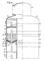
- the installation shown in the figures treats the oil between the supply line 1 and the outlet line 2.
- the installation comprises a central column 3 and four superimposed annular cells 4,5,6,7, surrounding the central column 3
- the central column is delimited by a bottom 9 and by an interior ferrule 8. It is open upwards where it opens into a dome 10 connected to a tube 11 for discharging gas.
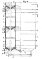
- the superimposed annular cells 4,5,6,7 surrounding the central column 3 are delimited by the interior ferrule 8, an exterior ferrule 13 and annular conical bottoms14.
- Each annular conical bottom has two parts in the form of a truncated cone.
- the inner truncated cone has its top directed upwards and the cone truncated outside with its top directed downwards.
- the cover 12 connected to the outer shell 13 and carrying the dome 10 completes the construction.
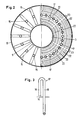
- each of the chambers constituting the annular cells 4,5,6,7 are arranged radially a series of oil distribution ramps 15.
- the distribution ramps 15 of the upper cell are connected to an annular tube 16 which is in turn connected to the pipe 1 for supplying oil.
- the distribution ramps 15 of the annular cells 5, 6, and 7 are supplied from the immediately upper cell 4,5, 6 via siphons 17.
- Each of these siphons 17 has a short branch 18 whose end lower is located near the lower part of the bottom 14 of the upper cell 4,5,6 and a long branch 19 crossing this bottom 14 and connected to a distribution ramp 15 of a lower cell 5,6,7 .
- Siphons 20 similar to siphons 17 have the lower end of their short branch near the lowest part of the bottom 14 of the lower cell 7. Their long branch crosses this bottom 14 of the lower cell 7 and is connected to a annular manifold 21 which is connected to the outlet pipe 2. Above the bottom 14 of each of the cells 4,5,6,7 are arranged annular pipes 22 having orifices directed upwards. In each of cells 4,5,6 and 7, said annular pipes 22 are connected to several tubes 23. These tubes 23 are connected to a source of water vapor.
- Normally closed tubes 24 are connected to a lower part of the bottom 14 of each of the cells 4,5,6,7.
- the tubes 24 are only used for emptying the cells when an oil of another quality is to be treated but do not intervene in normal operation of the installation.
- Openings are made in the inner shell 8 in each of cells 5, 6 and 7 just below the bottom 14 of the immediately upper cell 4,5, 6.
- Deflectors 25 are placed in these openings.
- the upper cell 4 is not closed at the top and therefore communicates through the upper part of the central column 3 with the interior of the dome 10. In the upper part of the upper cell 4 are placed deflectors 26.
- the upper cell 4 is provided with heating means constituted by tubes 27 inside of which steam can circulate serving only for heating the oil contained in this cell.
- the inlet and outlet of these tubes 27 have been designated by 28 and 29.
- the steam circulating in these tubes 27 is used only for heating and does not come into direct contact with the oil.
- the oil is introduced into the upper cell from the supply line 1, through the annular tube 16, through the distribution ramps 15.
- the oil is treated in this upper cell in a manner which will be described more in detail below and is evacuated from this upper cell 4 by the siphons 17 connecting this cell to that located immediately below the latter.
- the siphons 17 of cell 4 therefore supply the distribution booms 15 of cell 5.
- the oil from the latter passes through the siphons 17 of this cell 5 to the distribution booms 15 located in cell 6.
- the siphons of cell 6 bring the oil from the latter to the distribution ramps 15 of the lower cell 7.
- the siphons 20 of the latter pass the oil from this lower cell to the annular collector 21 and from there to the outlet pipe 2.
- each of the cells is filled with oil over a height ranging from 200 to 1200 millimeters depending on the nature of the product to be treated.
- the oil descends continuously from an upper surface of liquid located at a certain distance from the supply ramps 15 as far as the bottom of the cell, from where it is evacuated by the siphons.
- the movement of the oil in the cells is in principle rectilinear, uniform and vertical and the speed of this downward movement of the oil in the cells is slow and of the order of 1 cm / sec. .
- live steam is injected through the calibrated orifices of equal diameter formed in the upper parts of the annular pipes 22.
- the steam injected through these orifices of the annular pipes 22 is dispersed in the oil of the cell in the form of a multitude of ascending bubbles of small size. On the surface of the liquid these bubbles form a layer of foam and burst under the effect of the low pressure.
- a very low pressure of the order of 3 to 5 millibars, is maintained throughout the installation by a suction exerted on the tube 11 for discharging gas connected to the dome 10.
- the low pressure also prevails in the cells since the interior of the latter is in communication with the central column 3 and therefore with the dome 10 through the openings provided with deflectors 25 and 26.
- the bursting bubble layer is thick several centimeters and therefore it exposes the oil to a large distillation surface, in practice several tens of m2, under the lowest pressure prevailing in the installation.
- the heat exchanger tubes 27 are immersed in the mass of the liquid under treatment.
- the oil preheated beforehand outside the installation is heated there to the temperature required to accomplish the deodorization and / or deacidification.
- Siphons 17 and 20 maintain constant levels in all cells 4,5,6,7.
- the oil or fat is therefore treated continuously as a layer descending uniformly in each cell and flowing from one cell to another continuously.
- Rapid processing is a very important condition for certain fats which can only be exposed for a limited time at high temperature.
- the liquid subjected to the treatment is not necessarily oil or animal or vegetable fat which must be deodorized or deacidified.
- It can be any liquid from which an undesirable material is to be removed by means of any vapor, therefore not necessarily by means of water vapor, provided that the undesirable material is volatile under the conditions of treatment.
- the number of cells can be greater than or less than four and an installation can even be limited to a single cell, for example if it is intended for predistillation and / or predesodorisation and is followed by a device of another type completing distillation and / or deodorization continuously, semi-continuously or even discontinuously.
- the absolute pressure may be different from that mentioned above.
Landscapes
- Chemical & Material Sciences (AREA)
- Chemical Kinetics & Catalysis (AREA)
- Life Sciences & Earth Sciences (AREA)
- Microbiology (AREA)
- Engineering & Computer Science (AREA)
- Oil, Petroleum & Natural Gas (AREA)
- Wood Science & Technology (AREA)
- Organic Chemistry (AREA)
- Vaporization, Distillation, Condensation, Sublimation, And Cold Traps (AREA)
- Degasification And Air Bubble Elimination (AREA)
- Cleaning By Liquid Or Steam (AREA)
Priority Applications (1)
| Application Number | Priority Date | Filing Date | Title |
|---|---|---|---|
| MYPI87002892A MY101782A (en) | 1985-10-16 | 1987-10-12 | Method for removing a volatile material from a liquid and equipment for the working of this method |
Applications Claiming Priority (2)
| Application Number | Priority Date | Filing Date | Title |
|---|---|---|---|
| LU86121A LU86121A1 (fr) | 1985-10-16 | 1985-10-16 | Procede d'elimination d'une matiere volatile d'un liquide et installation pour la mise en oeuvre de ce procede |
| LU86121 | 1985-10-16 |
Publications (3)
| Publication Number | Publication Date |
|---|---|
| EP0219178A2 true EP0219178A2 (de) | 1987-04-22 |
| EP0219178A3 EP0219178A3 (en) | 1988-06-08 |
| EP0219178B1 EP0219178B1 (de) | 1991-02-27 |
Family
ID=19730566
Family Applications (1)
| Application Number | Title | Priority Date | Filing Date |
|---|---|---|---|
| EP86201794A Expired - Lifetime EP0219178B1 (de) | 1985-10-16 | 1986-10-15 | Verfahren zur Entfernung flüchtiger Stoffe aus einer Flüssigkeit und Vorrichtung zur Durchführung dieses Verfahrens |
Country Status (5)
| Country | Link |
|---|---|
| EP (1) | EP0219178B1 (de) |
| DE (1) | DE3677693D1 (de) |
| IN (1) | IN166834B (de) |
| LU (1) | LU86121A1 (de) |
| MY (1) | MY101782A (de) |
Cited By (1)
| Publication number | Priority date | Publication date | Assignee | Title |
|---|---|---|---|---|
| CN112126514A (zh) * | 2020-09-23 | 2020-12-25 | 周红茹 | 一种油脂精炼系统 |
Family Cites Families (4)
| Publication number | Priority date | Publication date | Assignee | Title |
|---|---|---|---|---|
| FR1272228A (fr) * | 1960-10-22 | 1961-09-22 | Pintsch Bamag Ag | Procédé de désodorisation continue de graisses et huiles végétales et animales au moyen de vapeur passant travers ces graisses ou huiles |
| DE1235487B (de) * | 1961-12-19 | 1967-03-02 | Pintsch Bamag Ag | Vorrichtung zur kontinuierlichen Desodorisierung von vegetabilen und animalischen Fetten und OElen mittels durchstroemenden Dampfes |
| NL173768C (nl) * | 1971-06-01 | 1984-03-01 | Stork Amsterdam | Werkwijze en inrichting voor het onder vacuuem behandelen van vloeistoffen met een gasvormig stripmedium. |
| US4072482A (en) * | 1976-06-21 | 1978-02-07 | The Nisshin Oil Mills, Ltd. | Continuous deodorizing apparatus of fat and oil |
-
1985
- 1985-10-16 LU LU86121A patent/LU86121A1/xx unknown
-
1986
- 1986-10-15 EP EP86201794A patent/EP0219178B1/de not_active Expired - Lifetime
- 1986-10-15 DE DE8686201794T patent/DE3677693D1/de not_active Expired - Lifetime
-
1987
- 1987-02-25 IN IN144/CAL/87A patent/IN166834B/en unknown
- 1987-10-12 MY MYPI87002892A patent/MY101782A/en unknown
Cited By (1)
| Publication number | Priority date | Publication date | Assignee | Title |
|---|---|---|---|---|
| CN112126514A (zh) * | 2020-09-23 | 2020-12-25 | 周红茹 | 一种油脂精炼系统 |
Also Published As
| Publication number | Publication date |
|---|---|
| DE3677693D1 (de) | 1991-04-04 |
| EP0219178A3 (en) | 1988-06-08 |
| MY101782A (en) | 1992-01-17 |
| IN166834B (de) | 1990-07-21 |
| LU86121A1 (fr) | 1987-06-02 |
| EP0219178B1 (de) | 1991-02-27 |
Similar Documents
| Publication | Publication Date | Title |
|---|---|---|
| US3933953A (en) | Apparatus for deodorizing fats and oils | |
| BE889811Q (fr) | Procede et appareil de chauffage d'eau | |
| FR2540739A1 (fr) | Dispositif et installations pour la distillation par evaporation en couches minces, en particulier pour hydrocarbures, et procede de mise en oeuvre de ce dispositif | |
| CA2173337C (fr) | Procede et installation pour le traitement des semences et des bulbes | |
| EP0570306B1 (de) | Einrichtung zum Extrahieren, Konzentrieren und Abscheiden von biochemischen produkten aus pflänzlichen oder tierischen biologischen Stoffen | |
| EP0243220A1 (de) | Verfahren und Vorrichtung zur Ultraschallextraktion von ölhaltigen Stoffen aus ölhaltigen Saaten | |
| EP0219178B1 (de) | Verfahren zur Entfernung flüchtiger Stoffe aus einer Flüssigkeit und Vorrichtung zur Durchführung dieses Verfahrens | |
| FR2680951A1 (fr) | Procede, produit obtenu avec le procede et dispositif de traitement de surface ou d'enrobage d'un produit vegetal, alimentaire ou agro-alimentaire. | |
| EP0045256A2 (de) | Verfahren und Vorrichtung zum Vergasen von Pflanzenmaterialien | |
| FR2528444A1 (fr) | Procede de craquage thermique d'huiles d'hydrocarbures | |
| FR2694705A1 (fr) | Procédé d'extraction par solvant en continu avec traitement par ultrasons et colonne pour la mise en Óoeuvre de ce procédé. | |
| FR2462448A1 (fr) | Procede d'elimination de chlorure de vinyle monimere d'une suspension de resine de chlorure de vinyle, par traitement a la vapeur d'eau, et appareil utilise pour la mise en oeuvre d'un tel procede | |
| FR3070044A1 (fr) | Procede de fermentation d’un jus contenant des sucres et appareil pour sa mise en œuvre | |
| CH644490A5 (fr) | Appareillage pour la culture hydroponique de plantes. | |
| FR2623794A1 (fr) | Dispositif d'epuration biologique continu du type a circulation vers le haut d'eaux a traiter | |
| EP0295182B1 (de) | Verfahren zum Kondensieren eines Dampfes, Vorrichtung zur Durchführung sowie eine solche Vorrichtung enthaltender Evaporator | |
| FR2486412A1 (fr) | Procede pour ameliorer le fonctionnement des colonnes d'extraction par solvant et colonne etablie pour sa mise en oeuvre | |
| FR2528443A1 (fr) | Procede de craquage thermique d'huiles d'hydrocarbures | |
| BE567756A (de) | ||
| BE505345A (de) | ||
| FR2597304A1 (fr) | Dispositif pour le pelage sous vide de fruits et de legumes. | |
| EP0332550A2 (de) | Vorrichtung für die gleichzeitige Warmwasser- und Kohlensäureerzeugung und landwirtschaftliche Anlage für deren Anwendung | |
| BE494781A (de) | ||
| FR3137302A1 (fr) | Système et procédé d’extraction de molécules volatiles provenant de matière première végétales | |
| FR2846334A1 (fr) | Procede de traitement de dechets en polyethylene ou autres polyolefines prealablement a leur craquage thermique |
Legal Events
| Date | Code | Title | Description |
|---|---|---|---|
| PUAI | Public reference made under article 153(3) epc to a published international application that has entered the european phase |
Free format text: ORIGINAL CODE: 0009012 |
|
| AK | Designated contracting states |
Kind code of ref document: A2 Designated state(s): DE FR GB IT |
|
| PUAL | Search report despatched |
Free format text: ORIGINAL CODE: 0009013 |
|
| AK | Designated contracting states |
Kind code of ref document: A3 Designated state(s): DE FR GB IT |
|
| 17P | Request for examination filed |
Effective date: 19880727 |
|
| 17Q | First examination report despatched |
Effective date: 19890921 |
|
| GRAA | (expected) grant |
Free format text: ORIGINAL CODE: 0009210 |
|
| AK | Designated contracting states |
Kind code of ref document: B1 Designated state(s): DE FR GB IT |
|
| GBT | Gb: translation of ep patent filed (gb section 77(6)(a)/1977) | ||
| REF | Corresponds to: |
Ref document number: 3677693 Country of ref document: DE Date of ref document: 19910404 |
|
| ITF | It: translation for a ep patent filed | ||
| PLBE | No opposition filed within time limit |
Free format text: ORIGINAL CODE: 0009261 |
|
| STAA | Information on the status of an ep patent application or granted ep patent |
Free format text: STATUS: NO OPPOSITION FILED WITHIN TIME LIMIT |
|
| 26N | No opposition filed | ||
| PGFP | Annual fee paid to national office [announced via postgrant information from national office to epo] |
Ref country code: FR Payment date: 19920715 Year of fee payment: 7 |
|
| PGFP | Annual fee paid to national office [announced via postgrant information from national office to epo] |
Ref country code: GB Payment date: 19921014 Year of fee payment: 7 |
|
| PG25 | Lapsed in a contracting state [announced via postgrant information from national office to epo] |
Ref country code: GB Effective date: 19931015 |
|
| PGFP | Annual fee paid to national office [announced via postgrant information from national office to epo] |
Ref country code: DE Payment date: 19940324 Year of fee payment: 8 |
|
| GBPC | Gb: european patent ceased through non-payment of renewal fee |
Effective date: 19931015 |
|
| PG25 | Lapsed in a contracting state [announced via postgrant information from national office to epo] |
Ref country code: FR Effective date: 19940630 |
|
| REG | Reference to a national code |
Ref country code: FR Ref legal event code: ST |
|
| PG25 | Lapsed in a contracting state [announced via postgrant information from national office to epo] |
Ref country code: DE Effective date: 19950701 |
|
| PG25 | Lapsed in a contracting state [announced via postgrant information from national office to epo] |
Ref country code: IT Free format text: LAPSE BECAUSE OF NON-PAYMENT OF DUE FEES;WARNING: LAPSES OF ITALIAN PATENTS WITH EFFECTIVE DATE BEFORE 2007 MAY HAVE OCCURRED AT ANY TIME BEFORE 2007. THE CORRECT EFFECTIVE DATE MAY BE DIFFERENT FROM THE ONE RECORDED. Effective date: 20051015 |