EP0218854B1 - Process and apparatus for regenerating spent reprocessing extraction solvent - Google Patents
Process and apparatus for regenerating spent reprocessing extraction solvent Download PDFInfo
- Publication number
- EP0218854B1 EP0218854B1 EP86111634A EP86111634A EP0218854B1 EP 0218854 B1 EP0218854 B1 EP 0218854B1 EP 86111634 A EP86111634 A EP 86111634A EP 86111634 A EP86111634 A EP 86111634A EP 0218854 B1 EP0218854 B1 EP 0218854B1
- Authority
- EP
- European Patent Office
- Prior art keywords
- hollow fibers
- aqueous solution
- outlet
- solvent
- alkaline
- Prior art date
- Legal status (The legal status is an assumption and is not a legal conclusion. Google has not performed a legal analysis and makes no representation as to the accuracy of the status listed.)
- Expired
Links
- 238000000034 method Methods 0.000 title claims description 18
- 230000001172 regenerating effect Effects 0.000 title claims description 18
- 239000002904 solvent Substances 0.000 title description 58
- 238000000605 extraction Methods 0.000 title description 12
- 238000012958 reprocessing Methods 0.000 title description 6
- 239000012510 hollow fiber Substances 0.000 claims description 86
- HEMHJVSKTPXQMS-UHFFFAOYSA-M Sodium hydroxide Chemical compound [OH-].[Na+] HEMHJVSKTPXQMS-UHFFFAOYSA-M 0.000 claims description 50
- OAKJQQAXSVQMHS-UHFFFAOYSA-N Hydrazine Chemical compound NN OAKJQQAXSVQMHS-UHFFFAOYSA-N 0.000 claims description 40
- 239000007864 aqueous solution Substances 0.000 claims description 40
- MUBZPKHOEPUJKR-UHFFFAOYSA-N Oxalic acid Chemical compound OC(=O)C(O)=O MUBZPKHOEPUJKR-UHFFFAOYSA-N 0.000 claims description 29
- 150000001450 anions Chemical class 0.000 claims description 28
- 150000001768 cations Chemical class 0.000 claims description 22
- 239000011975 tartaric acid Substances 0.000 claims description 20
- FEWJPZIEWOKRBE-JCYAYHJZSA-N Dextrotartaric acid Chemical compound OC(=O)[C@H](O)[C@@H](O)C(O)=O FEWJPZIEWOKRBE-JCYAYHJZSA-N 0.000 claims description 19
- FEWJPZIEWOKRBE-UHFFFAOYSA-N Tartaric acid Natural products [H+].[H+].[O-]C(=O)C(O)C(O)C([O-])=O FEWJPZIEWOKRBE-UHFFFAOYSA-N 0.000 claims description 19
- 235000002906 tartaric acid Nutrition 0.000 claims description 19
- 239000003960 organic solvent Substances 0.000 claims description 17
- 230000002209 hydrophobic effect Effects 0.000 claims description 14
- 230000002378 acidificating effect Effects 0.000 claims description 12
- 235000006408 oxalic acid Nutrition 0.000 claims description 9
- 239000000835 fiber Substances 0.000 claims description 7
- 239000002699 waste material Substances 0.000 claims description 7
- HZAXFHJVJLSVMW-UHFFFAOYSA-N 2-Aminoethan-1-ol Chemical compound NCCO HZAXFHJVJLSVMW-UHFFFAOYSA-N 0.000 claims description 6
- FERIUCNNQQJTOY-UHFFFAOYSA-N Butyric acid Chemical compound CCCC(O)=O FERIUCNNQQJTOY-UHFFFAOYSA-N 0.000 claims description 4
- BDAGIHXWWSANSR-UHFFFAOYSA-N methanoic acid Natural products OC=O BDAGIHXWWSANSR-UHFFFAOYSA-N 0.000 claims description 4
- AVXURJPOCDRRFD-UHFFFAOYSA-N Hydroxylamine Chemical compound ON AVXURJPOCDRRFD-UHFFFAOYSA-N 0.000 claims description 3
- BVKZGUZCCUSVTD-UHFFFAOYSA-N carbonic acid Chemical compound OC(O)=O BVKZGUZCCUSVTD-UHFFFAOYSA-N 0.000 claims description 3
- 239000000203 mixture Substances 0.000 claims description 3
- 229920003002 synthetic resin Polymers 0.000 claims description 3
- 239000000057 synthetic resin Substances 0.000 claims description 3
- OSWFIVFLDKOXQC-UHFFFAOYSA-N 4-(3-methoxyphenyl)aniline Chemical compound COC1=CC=CC(C=2C=CC(N)=CC=2)=C1 OSWFIVFLDKOXQC-UHFFFAOYSA-N 0.000 claims description 2
- 235000019253 formic acid Nutrition 0.000 claims description 2
- KWYUFKZDYYNOTN-UHFFFAOYSA-M Potassium hydroxide Chemical compound [OH-].[K+] KWYUFKZDYYNOTN-UHFFFAOYSA-M 0.000 claims 3
- 239000003929 acidic solution Substances 0.000 claims 1
- 239000012670 alkaline solution Substances 0.000 claims 1
- 150000002500 ions Chemical class 0.000 description 31
- 239000003795 chemical substances by application Substances 0.000 description 28
- 229910021645 metal ion Inorganic materials 0.000 description 21
- -1 polypropylene Polymers 0.000 description 19
- 239000000243 solution Substances 0.000 description 18
- GRYLNZFGIOXLOG-UHFFFAOYSA-N Nitric acid Chemical compound O[N+]([O-])=O GRYLNZFGIOXLOG-UHFFFAOYSA-N 0.000 description 13
- 229910017604 nitric acid Inorganic materials 0.000 description 13
- 239000012528 membrane Substances 0.000 description 11
- 239000012071 phase Substances 0.000 description 11
- 239000012535 impurity Substances 0.000 description 10
- 239000008346 aqueous phase Substances 0.000 description 9
- CDBYLPFSWZWCQE-UHFFFAOYSA-L Sodium Carbonate Chemical compound [Na+].[Na+].[O-]C([O-])=O CDBYLPFSWZWCQE-UHFFFAOYSA-L 0.000 description 8
- 229910052770 Uranium Inorganic materials 0.000 description 8
- 239000012459 cleaning agent Substances 0.000 description 8
- 239000002244 precipitate Substances 0.000 description 7
- 238000000926 separation method Methods 0.000 description 6
- STCOOQWBFONSKY-UHFFFAOYSA-N tributyl phosphate Chemical compound CCCCOP(=O)(OCCCC)OCCCC STCOOQWBFONSKY-UHFFFAOYSA-N 0.000 description 6
- 229910052778 Plutonium Inorganic materials 0.000 description 5
- 239000011148 porous material Substances 0.000 description 5
- 239000000126 substance Substances 0.000 description 5
- JFALSRSLKYAFGM-UHFFFAOYSA-N uranium(0) Chemical compound [U] JFALSRSLKYAFGM-UHFFFAOYSA-N 0.000 description 5
- XLYOFNOQVPJJNP-UHFFFAOYSA-N water Substances O XLYOFNOQVPJJNP-UHFFFAOYSA-N 0.000 description 5
- 229910052726 zirconium Inorganic materials 0.000 description 5
- 239000002253 acid Substances 0.000 description 4
- SNRUBQQJIBEYMU-UHFFFAOYSA-N dodecane Chemical compound CCCCCCCCCCCC SNRUBQQJIBEYMU-UHFFFAOYSA-N 0.000 description 4
- 229940094933 n-dodecane Drugs 0.000 description 4
- 229910000029 sodium carbonate Inorganic materials 0.000 description 4
- QTBSBXVTEAMEQO-UHFFFAOYSA-N Acetic acid Chemical compound CC(O)=O QTBSBXVTEAMEQO-UHFFFAOYSA-N 0.000 description 3
- 239000004743 Polypropylene Substances 0.000 description 3
- 125000000129 anionic group Chemical group 0.000 description 3
- 125000002091 cationic group Chemical group 0.000 description 3
- 238000004140 cleaning Methods 0.000 description 3
- 239000000463 material Substances 0.000 description 3
- 229910000000 metal hydroxide Inorganic materials 0.000 description 3
- 150000004692 metal hydroxides Chemical class 0.000 description 3
- 150000007524 organic acids Chemical class 0.000 description 3
- OYEHPCDNVJXUIW-UHFFFAOYSA-N plutonium atom Chemical compound [Pu] OYEHPCDNVJXUIW-UHFFFAOYSA-N 0.000 description 3
- 229920001155 polypropylene Polymers 0.000 description 3
- 238000001556 precipitation Methods 0.000 description 3
- 230000008929 regeneration Effects 0.000 description 3
- 238000011069 regeneration method Methods 0.000 description 3
- NWUYHJFMYQTDRP-UHFFFAOYSA-N 1,2-bis(ethenyl)benzene;1-ethenyl-2-ethylbenzene;styrene Chemical compound C=CC1=CC=CC=C1.CCC1=CC=CC=C1C=C.C=CC1=CC=CC=C1C=C NWUYHJFMYQTDRP-UHFFFAOYSA-N 0.000 description 2
- PAYRUJLWNCNPSJ-UHFFFAOYSA-N Aniline Chemical compound NC1=CC=CC=C1 PAYRUJLWNCNPSJ-UHFFFAOYSA-N 0.000 description 2
- 239000004698 Polyethylene Substances 0.000 description 2
- JUJWROOIHBZHMG-UHFFFAOYSA-N Pyridine Chemical compound C1=CC=NC=C1 JUJWROOIHBZHMG-UHFFFAOYSA-N 0.000 description 2
- QCWXUUIWCKQGHC-UHFFFAOYSA-N Zirconium Chemical compound [Zr] QCWXUUIWCKQGHC-UHFFFAOYSA-N 0.000 description 2
- 239000003729 cation exchange resin Substances 0.000 description 2
- 230000006866 deterioration Effects 0.000 description 2
- 238000004821 distillation Methods 0.000 description 2
- 238000005342 ion exchange Methods 0.000 description 2
- 238000004519 manufacturing process Methods 0.000 description 2
- 239000003758 nuclear fuel Substances 0.000 description 2
- 229920002239 polyacrylonitrile Polymers 0.000 description 2
- 229920000573 polyethylene Polymers 0.000 description 2
- 229920000915 polyvinyl chloride Polymers 0.000 description 2
- 239000004800 polyvinyl chloride Substances 0.000 description 2
- 230000005855 radiation Effects 0.000 description 2
- 230000002285 radioactive effect Effects 0.000 description 2
- BVKZGUZCCUSVTD-UHFFFAOYSA-L Carbonate Chemical compound [O-]C([O-])=O BVKZGUZCCUSVTD-UHFFFAOYSA-L 0.000 description 1
- JYFHYPJRHGVZDY-UHFFFAOYSA-N Dibutyl phosphate Chemical compound CCCCOP(O)(=O)OCCCC JYFHYPJRHGVZDY-UHFFFAOYSA-N 0.000 description 1
- DGAQECJNVWCQMB-PUAWFVPOSA-M Ilexoside XXIX Chemical compound C[C@@H]1CC[C@@]2(CC[C@@]3(C(=CC[C@H]4[C@]3(CC[C@@H]5[C@@]4(CC[C@@H](C5(C)C)OS(=O)(=O)[O-])C)C)[C@@H]2[C@]1(C)O)C)C(=O)O[C@H]6[C@@H]([C@H]([C@@H]([C@H](O6)CO)O)O)O.[Na+] DGAQECJNVWCQMB-PUAWFVPOSA-M 0.000 description 1
- NTIZESTWPVYFNL-UHFFFAOYSA-N Methyl isobutyl ketone Chemical compound CC(C)CC(C)=O NTIZESTWPVYFNL-UHFFFAOYSA-N 0.000 description 1
- UIHCLUNTQKBZGK-UHFFFAOYSA-N Methyl isobutyl ketone Natural products CCC(C)C(C)=O UIHCLUNTQKBZGK-UHFFFAOYSA-N 0.000 description 1
- CTQNGGLPUBDAKN-UHFFFAOYSA-N O-Xylene Chemical compound CC1=CC=CC=C1C CTQNGGLPUBDAKN-UHFFFAOYSA-N 0.000 description 1
- 239000004952 Polyamide Substances 0.000 description 1
- 239000004793 Polystyrene Substances 0.000 description 1
- GSEJCLTVZPLZKY-UHFFFAOYSA-N Triethanolamine Chemical compound OCCN(CCO)CCO GSEJCLTVZPLZKY-UHFFFAOYSA-N 0.000 description 1
- HXPJIEMQFBIQMQ-UHFFFAOYSA-N [Zr].[U] Chemical compound [Zr].[U] HXPJIEMQFBIQMQ-UHFFFAOYSA-N 0.000 description 1
- 150000007513 acids Chemical class 0.000 description 1
- 238000005054 agglomeration Methods 0.000 description 1
- 230000002776 aggregation Effects 0.000 description 1
- 150000008044 alkali metal hydroxides Chemical class 0.000 description 1
- 230000015572 biosynthetic process Effects 0.000 description 1
- 239000008139 complexing agent Substances 0.000 description 1
- 238000011109 contamination Methods 0.000 description 1
- 150000004696 coordination complex Chemical class 0.000 description 1
- 230000001419 dependent effect Effects 0.000 description 1
- 238000004880 explosion Methods 0.000 description 1
- 239000011521 glass Substances 0.000 description 1
- 230000005764 inhibitory process Effects 0.000 description 1
- 238000003780 insertion Methods 0.000 description 1
- 230000037431 insertion Effects 0.000 description 1
- 238000007689 inspection Methods 0.000 description 1
- 238000000622 liquid--liquid extraction Methods 0.000 description 1
- 238000012423 maintenance Methods 0.000 description 1
- 150000001455 metallic ions Chemical class 0.000 description 1
- 150000007522 mineralic acids Chemical class 0.000 description 1
- 238000002156 mixing Methods 0.000 description 1
- 150000007530 organic bases Chemical class 0.000 description 1
- 239000012074 organic phase Substances 0.000 description 1
- 230000000149 penetrating effect Effects 0.000 description 1
- 229920002492 poly(sulfone) Polymers 0.000 description 1
- 229920002647 polyamide Polymers 0.000 description 1
- 229920000728 polyester Polymers 0.000 description 1
- 239000002861 polymer material Substances 0.000 description 1
- 229920002223 polystyrene Polymers 0.000 description 1
- 229920002451 polyvinyl alcohol Polymers 0.000 description 1
- 235000019422 polyvinyl alcohol Nutrition 0.000 description 1
- 239000000047 product Substances 0.000 description 1
- UMJSCPRVCHMLSP-UHFFFAOYSA-N pyridine Natural products COC1=CC=CN=C1 UMJSCPRVCHMLSP-UHFFFAOYSA-N 0.000 description 1
- 238000000197 pyrolysis Methods 0.000 description 1
- 239000002901 radioactive waste Substances 0.000 description 1
- VSZWPYCFIRKVQL-UHFFFAOYSA-N selanylidenegallium;selenium Chemical compound [Se].[Se]=[Ga].[Se]=[Ga] VSZWPYCFIRKVQL-UHFFFAOYSA-N 0.000 description 1
- 229910052708 sodium Inorganic materials 0.000 description 1
- 239000011734 sodium Substances 0.000 description 1
- 239000007787 solid Substances 0.000 description 1
- 239000002910 solid waste Substances 0.000 description 1
- 238000000638 solvent extraction Methods 0.000 description 1
- 239000007858 starting material Substances 0.000 description 1
- 229940095064 tartrate Drugs 0.000 description 1
- 239000008096 xylene Substances 0.000 description 1
Images



Classifications
-
- B—PERFORMING OPERATIONS; TRANSPORTING
- B01—PHYSICAL OR CHEMICAL PROCESSES OR APPARATUS IN GENERAL
- B01D—SEPARATION
- B01D63/00—Apparatus in general for separation processes using semi-permeable membranes
- B01D63/02—Hollow fibre modules
- B01D63/021—Manufacturing thereof
- B01D63/0233—Manufacturing thereof forming the bundle
-
- B—PERFORMING OPERATIONS; TRANSPORTING
- B01—PHYSICAL OR CHEMICAL PROCESSES OR APPARATUS IN GENERAL
- B01D—SEPARATION
- B01D61/00—Processes of separation using semi-permeable membranes, e.g. dialysis, osmosis or ultrafiltration; Apparatus, accessories or auxiliary operations specially adapted therefor
- B01D61/24—Dialysis ; Membrane extraction
- B01D61/28—Apparatus therefor
-
- B—PERFORMING OPERATIONS; TRANSPORTING
- B01—PHYSICAL OR CHEMICAL PROCESSES OR APPARATUS IN GENERAL
- B01D—SEPARATION
- B01D63/00—Apparatus in general for separation processes using semi-permeable membranes
- B01D63/02—Hollow fibre modules
- B01D63/04—Hollow fibre modules comprising multiple hollow fibre assemblies
-
- B—PERFORMING OPERATIONS; TRANSPORTING
- B01—PHYSICAL OR CHEMICAL PROCESSES OR APPARATUS IN GENERAL
- B01D—SEPARATION
- B01D2319/00—Membrane assemblies within one housing
- B01D2319/06—Use of membranes of different materials or properties within one module
-
- B—PERFORMING OPERATIONS; TRANSPORTING
- B01—PHYSICAL OR CHEMICAL PROCESSES OR APPARATUS IN GENERAL
- B01D—SEPARATION
- B01D2325/00—Details relating to properties of membranes
- B01D2325/38—Hydrophobic membranes
Definitions
- This invention relates to a process for regenerating a spent extraction solvent containing anions and cations used in e.g. nuclear power plants by separating and removing these ions from the extraction solvent and an apparatus used therefor.
- This invention is particularly suitable for separating and removing ions contained in an organic solvent for reprocessing in large amounts.
- an extraction solvent was regenerated by cleaning the extraction solvent with an alkaline cleaning agent such as sodium carbonate, triethanolamine, etc. by using a liquid-liquid extraction apparatus such as a mixer-settler, etc. (e.g. US-A 4 059 671).
- an alkaline cleaning agent such as sodium carbonate, triethanolamine, etc.
- a liquid-liquid extraction apparatus such as a mixer-settler, etc.
- This invention provides a process for regenerating a spent organic solvent containing anions and cations by separating and removing the anions and cations from the organic solvent, the process comprising: flowing an organic solvent containing anions and cations around a bundle of microporous hydrophobic hollow fibers; and flowing simultaneously one or more alkaline aqueous solutions inside the lumen of a first set of said fibers and one or more acidic aqueous solutions inside the lumen of the rest of said fibers.
- This invention also provides an apparatus used for such a process.
- a spent reprocessing extraction solvent can be regenerated without producing a precipitate by selectively removing cationic impurities by an aqueous acidic cleaning agent via a microporous hydrophobic membrane formed as hollow fibers and by selectively removing anionic impurities by an alkaline aqueous cleaning agent via such microporous hydrophobic hollow fibers at the same time.
- TBP tributyl phosphate
- n-dodecane n-dodecane
- DBP dibutyl phosphate
- metal ions such as zirconium ions, etc. show a tendency to remain in the solvent when DPB is present. Since these metal ions are radioactive, deterioration of the extraction solvent further proceeds.
- the solvent an organic phase
- the solvent is separated from the aqueous phase via microporous hydrophobic hollow fibers according to this invention.
- microporous hydrophobic hollow fibers are used between the solvent containing cationic and anionic impurities (or ions) and aqueous solution phases for removing these ions.
- the properties of hydrophobic are necessary for only passing ions through micro holes of the fibers.
- the microporous hydrophobic hollow fibers there can be used those made from synthetic or natural, organic or inorganic high polymer materials, for example, polyamides, polyacrylonitriles, polyethylene; polyesters, polypropylenes, polysulfones, polyvinyl alcohols, polyvinyl chloride, glass, etc.
- the use of said hydrophobic hollow fibers is preferable in order to enlarge the contact area between the spent solvent and two or more aqueous phases and to make the removing efficiency the same as that obtained by the mixer-settler method.
- Fig. 1 shows schematically a structure of hollow fiber, wherein A denotes a porous membrane, B a hollow portion, and C pores. Hollow fibers are slightly different in properties dependent on starting materials and production methods but usually have an inner diameter of 250 to 350 ⁇ .Lm and a thickness of 50 to 150 um.
- the porous membrane A has a number of pores C penetrating from the inner side to the outer side as shown in Fig. 1 (b). The open area ratio of 50% or more can easily be obtained.
- the outer diameter of hollow fiber is 1 mm or less, a very large surface area can be obtained by using a bundle of hollow fibers.
- Fig. 2 schematically shows a state of passing an organic solvent phase outside of the membrane A and passing a water phase inside, that is, the hollow portion, of the membrane A. Since the material of the membrane is hydrophobic, the water phase does not enter into pores C. In contrast, the solvent enters into pores to produce interfaces D between the solvent phase and the water phase at the inside (B) of the membrane. Through the interface D, impurities in the solvent can be extracted with the water phase.
- hollow fibers When hollow fibers are used, it becomes possible to remove cations and anions contained in the solvent selectively and separately by contacting two or more aqueous phase ion removing agents with the solvent via the microporous membranes of hollow fibers.
- Fig. 3 schematically shows a case when two kinds of ion removing agents are used.
- an anion removing agent E is passed and DBP is mainly removed selectively.
- a cation removing agent F is passed and metal ions of uranium (U), zirconium (Zr), etc. are mainly removed selectively. Since ions can be selectively removed from a spent (or deteriorated) solvent, this treatment can be conducted depending on properties of ions present in the spent solvent.
- hollow fibers passing the anion removing agent and those passing the cation removing agent are arranged as closely as possible. This is because when DBP is removed from the spent solvent, the metal ions easily transfer to the aqueous phase. When the hollow fibers are separated with too far distances, it becomes possible that the metal ions flow into the anion removing agent. If possible, it is preferable to place hollow fibers passing the cation removing agent neighboring to hollow fibers passing the anion removing agent. Examples of such arrangement of hollow fiber modules are shown in Fig. 4, wherein H denotes cation removing hollow fibers and G denotes anion removing hollow fibers.
- pattern I When deterioration of the spent solvent is remarkable, the arrangement of pattern I is preferable, but the removal efficiency of DBP cannot be taken too high. It is possible to use various arrangements of hollow fiber modules passing two kinds of ion removing agents separately in various proportions other than the pattern II shown in Fig. 4. Any arrangement can be employed depending on the state of operation of nuclear power plants.
- the hollow fibers should have resistance to radiation to some extent. Further, since a small amount of nitric acid is dissolved in the spent solvent, the hollow fibers should have resistance to nitric acid as well as resistance to alkalis considering the use of an aqueous alkaline cleaning agent (anion removing agent).
- an aqueous alkaline cleaning agent anion removing agent.
- hollow fibers made from a synthetic resin such as polystyrene, polyvinyl chloride, polypropylene, polyethylene, polyacrylonitrile, or the like are preferable. Such materials can withstand the dose rate of 10 4 Gy or more and can be used for one year sufficiently. If necessary, the hollow fibers may be exchanged at every routine inspection.
- the hollow fibers can be produced by a conventional process disclosed in, for example, Japanese Patent Examined Publication No. 47-8595.
- the anion removing agent there can be used an aqueous solution (about 0.1 to 2 N) of alkali metal hydroxides such as NaOH, etc. In such a case, it is not necessary to consider entrapment of metal ions in the spent solvent. Thus, it is not necessary to add carbonate ions and tartrate ions to the aqueous solution.
- hydrazine and hydroxylamine have a fear of explosion in the presence of nitric acid and are very unstable. But, when they are used by passing through hollow fibers, they can be used safely, since a danger of mixing them in other nitric acid systems is very rare. Further, since these anion removing agents can be vaporized completely by pyrolysis, the use of them is excellent from the viewpoint of reducing the amount of solid waste. Further, when the selective separation is carried out by using hollow fibers, since no radioactive metal ions are contained in the resulting anion removing agent, the treatment therefore is easy. It is also possible to use other various organic bases such as ethanolamine, pyridine, aniline, etc. When ethanolamine is used as an anion removing agent, it can be recovered by distillation due to its chemical stability and reused again.
- Cations contained in the spent solvent include ions of zirconium, uranium, plutonium usually in 0.1 to 5 moles.
- the cation removing agent there can be used an acidic aqueous solution of an acid which can form complexes with high stability constants with zirconium uranium, and the like cations.
- the acid there can be used an inorganic acid such as carbonic acid, etc.; an organic acid such as formic acid, oxalic add, butyric acid, tartaric acid, etc., alone or as a mixture thereof.
- carbonic acid is very effective for uranium cations. It is possible to store uranium with a high concentration in an aqueous phase in the presence of CO S 2- or HCO s -.
- the use of an organic acid such as oxalic acid, tartaric acid, etc. is effective for removing zirconium.
- the use of an organic acid is preferable for reducing the volume of treated waste.
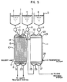
- This invention is illustrated further in detail referring to Rg. 5, wherein a spent organic solvent is regenerated by using as ion removing agents an aqueous solution of sodium hydroxide and an aqueous solution of oxalic acid in a first step and an aqueous solution of sodium hydroxide and an aqueous solution of nitric acid in a second step.
- oxalic acid storing tank 1 2N-oxalic acid aqueous solution 2 is stored, IN-NaOH aqueous solution 4 is stored in a sodium hydroxide storing tank 3 and O.lN-HNO s aqueous solution 6 is stored in a dilute nitric acid storing tank 5.
- pumps 7, 8 and 9 are connected, respectively, so as to pass individual aqueous solutions to a solvent regeneration apparatus.
- the solvent regeneration apparatus comprises a first step ion removing portion 10 and a second step ion removing portion 11.
- a spent organic solvent comprising 30% by volume of TBP and 70% by volume of n-dodecane containing impurities such as metal ions, DBP, etc.
- the 2N-oxalic acid aqueous solution 2 is fed to an oxalic acid forcing inlet 13 via the pump 7 and passed to hollow fibers 14 for passing oxalic acid.
- the sodium hydroxide aqueous solution used in the second step ion removing portion 11 is passed to hollow fibers 16 for passing sodium hydroxide via a sodium forcing inlet 15. Both hollow fibers 14 and 16 are rearranged in a hollow fibers initial crossing portion 17 so as to have the pattern I shown in Fig. 4.
- the metal ions such as U + 2, Zr+2, etc.
- the spent solvent treated in the first step ion removing portion 10 is passed to the second step ion removing portion II via a solvent transporting pipe 21.
- the sodium hydroxide aqueous solution is fed from the sodium hydroxide storing tank 3 via the pump 8 and entered into hollow fibers (not shown in the drawing) at a sodium hydroxide forcing inlet 22.
- Dilute nitric acid is passed to a nitric acid forcing inlet 23 from the dilute nitric acid storing tank 5 via the pump 9 and entered into hollow fibers (not shown in the drawing).
- the hollow fibers are rearranged at a hollow fiber initial crossing portion 24 so as to have the pattern II shown in Figure 4.
- the second step ion removing portion II precise separation of DBP by the sodium hydroxide aqueous solution, and precise separation of metal ions and extraction of the flowed ion removing agent by the dilute nitric acid are conducted by hollow fibers.
- hollow fibers are collected separately depending on the systems and the sodium hydroxide aqueous solution is passed from a sodium hydroxide outlet 26 to the first step ion removing portion 10.
- the dilute nitric acid is passed to an acid recovering system via a dilute nitric acid outlet 27.
- the solvent from which the cations and anions have been removed is taken out of a regenerated solvent outlet 28 to use again as a regenerated solvent.
- DBP removing ratio is more than 98% and metal ion removing ratio is more than 95%.
- the spent organic solvent can be regenerated by using an apparatus with a simple structure and with no moving portion. Further there is no fear of lowering the ion removing efficiency due to the formation of precipitates.
- FIG. 6 Another example of this invention is explained referring to Fig. 6, wherein the ion removing agents are regenerated and reused so as to reduce the amounts of radioactive wastes produced.
- Hydrazine from a hydrazine regenerating device 29 is sent to a solvent regenerating device 31 via a pump 30.
- hydrazine is supplemented from a hydrazine storing tank 32 by opening a valve 33.
- a 2N-tartaric acid solution from a tartaric acid solution regenerating device 34 is sent to the solvent regenerating device 31 via a pump 30'.
- tartaric acid is supplemented from a tartaric acid storing tank 35 by opening a valve 33'.
- Hydrazine is fed to a hollow fiber opening portion for hydrazine 36 in the solvent regenerating device 31.
- the hollow fibers 37 for passing hydrazine and the hollow fibers 39 for passing the tartaric acid solution are packed densely.
- Anions such as DBP, etc. are extacted with the hydrazine passing through the hollow fibers 37 and the metal ions are extracted with the tartaric acid solution passing through the hollow fibers 39.
- the solvent is flowed out from a solvent outlet 43 as a regenerated solvent. If necessary, the ion removing operation can be carried out by using one or more the same devices 31 as mentioned above.
- the hollow fibers passing hydrazine have openings at a hollow fiber opening portion 40 for hydrazine, from which the hydrazine extracting the anions is taken out and sent to the hydrazine regenerating device 29.
- Hydrazine N 2 H 4 -H 2 0
- DBP cannot vaporize under normal conditions. Therefore, the used hydrazine can be regenerated by distillation and reused repeatedly.
- the hollow fibers passing the tartaric acid solution have openings at a hollow fiber opening portion 41 for tartaric acid, from which the tartaric acid solution extracting the metal ions is taken out and sent to the tartaric acid solution regenerating device 34.
- the tartaric acid is regenerated in the device 34 and reused repeatedly.
- a cation exchange resin conventionally used is packed and the metal ions are removed by ion exchange. Since the amount of metal ions in the spent solvent is not so large in usual, the cation exchange resin can be used for a long time without exchanging.
- an ion removing operation can be carried out by passing an aqueous solution of an anion removing agent, an aqueous solution uranium and plutonium selectively removing agent and an aqueous solution of a cation removing agent through hollow fibers separately in contact with a spent solvent containing anions such as DBP and metal ions such as uranium ions, plutonium ions, zirconium ions, etc. via the porous membranes of hollow fibers.
- uranium and plutonium which are nuclear fuel substances and other radio nuclides can be recovered separately. Further, by this, a loss of nuclear fuel substances in the reprocessing step and the like can be prevented. In addition, contamination of a waste treating system by plutorium which has a long half-value period can be prevented so as to make the waste treatment simple.
Landscapes
- Chemical & Material Sciences (AREA)
- Chemical Kinetics & Catalysis (AREA)
- Engineering & Computer Science (AREA)
- Manufacturing & Machinery (AREA)
- Health & Medical Sciences (AREA)
- Urology & Nephrology (AREA)
- Water Supply & Treatment (AREA)
- Separation Using Semi-Permeable Membranes (AREA)
- Extraction Or Liquid Replacement (AREA)
Description
- This invention relates to a process for regenerating a spent extraction solvent containing anions and cations used in e.g. nuclear power plants by separating and removing these ions from the extraction solvent and an apparatus used therefor. This invention is particularly suitable for separating and removing ions contained in an organic solvent for reprocessing in large amounts.
- Heretofore, an extraction solvent was regenerated by cleaning the extraction solvent with an alkaline cleaning agent such as sodium carbonate, triethanolamine, etc. by using a liquid-liquid extraction apparatus such as a mixer-settler, etc. (e.g. US-A 4 059 671). But such a cleaning agent has problems in that it easily precipitates metal ions contained in the deteriorated solvent, the resulting precipitate is collected at an interface of the solvent and the cleaning agent so that it interferes with the removal of captured impurities and makes the separation of the solvent and the cleaning agent worse.
- On the other hand, "Journal of Membrane Science", Vol. 20, no. 2, Aug. 1984, pages 125-145 discloses the extraction of acetic acid from aqueous solutions into either methyl isobutyl ketone or xylene through a flat thin microporous polypropylene film or through hollow microporous hydrophobic fibers.
- It is an object of this invention to provide a process and an apparatus for regenerating a spent reprocessing extraction solvent without causing interference with cleaning operation accompanied by production of a precipitate in an alkaline environment.
- This invention provides a process for regenerating a spent organic solvent containing anions and cations by separating and removing the anions and cations from the organic solvent, the process comprising: flowing an organic solvent containing anions and cations around a bundle of microporous hydrophobic hollow fibers; and flowing simultaneously one or more alkaline aqueous solutions inside the lumen of a first set of said fibers and one or more acidic aqueous solutions inside the lumen of the rest of said fibers.
- This invention also provides an apparatus used for such a process.
-
- Fig. 1 (a) is a perspective and partially cross-sectional view of a structure of a hollow fiber.
- Fig. 1 (b) is an enlarged cross-sectional view of a part of the hollow fiber.
- Fig. 2 is an enlarged cross-sectional view of a hollow fiber membrane when a solvent is present outside thereof and an aqueous phase is present inside thereof.
- Fig. 3 is a perspective view for explaining the principle of solvent cleaning according to this invention.
- Fig. 4 is cross-sectional views showing typical patterns for arrangement of hollow fibers.
- Figs. 5 and 6 are diagrammatic views of apparatuses used in this invention.
- According to this invention, a spent reprocessing extraction solvent can be regenerated without producing a precipitate by selectively removing cationic impurities by an aqueous acidic cleaning agent via a microporous hydrophobic membrane formed as hollow fibers and by selectively removing anionic impurities by an alkaline aqueous cleaning agent via such microporous hydrophobic hollow fibers at the same time.
- As an extraction solvent for fuel-reprocessing in nuclear power plants, tributyl phosphate (hereinafter referred to as "TBP") diluted with n-dodecane is usually used. Both TBP and n-dodecane are decomposed by an influence of radiation or nitric acid to mostly produce acids. Among decomposed products of TBP, the produced amount of dibutyl phosphate (hereinafter referred to as "DBP") is large, which results in giving a great influence on the extraction behavior. Further, metal ions such as zirconium ions, etc. show a tendency to remain in the solvent when DPB is present. Since these metal ions are radioactive, deterioration of the extraction solvent further proceeds.
- In the regeneration step of the solvent, it is necessary to remove both anionic impurities such as DBP, etc. and cationic impurities such as zirconium ions, etc. from the solvent. In order to remove DBP, an aqueous sodium carbonate solution is usually used. But since metal ions easily transfer to an aqueous phase in the absence of DBP, they enter into the aqueous sodium carbonate solution. But since the aqueous sodium carbonate solution is strongly alkaline, the metal ions are easily precipitated by forming metal hydroxides.
- In order to prevent the precipitation, the solvent (an organic phase) is separated from the aqueous phase via microporous hydrophobic hollow fibers according to this invention. By employing such a process as removing impurities through said fibers, it becomes possible to separate and remove impurities by contacting two or more aqueous phases with the solvent.
- In this invention, microporous hydrophobic hollow fibers are used between the solvent containing cationic and anionic impurities (or ions) and aqueous solution phases for removing these ions. The properties of hydrophobic are necessary for only passing ions through micro holes of the fibers. As the microporous hydrophobic hollow fibers, there can be used those made from synthetic or natural, organic or inorganic high polymer materials, for example, polyamides, polyacrylonitriles, polyethylene; polyesters, polypropylenes, polysulfones, polyvinyl alcohols, polyvinyl chloride, glass, etc. The use of said hydrophobic hollow fibers is preferable in order to enlarge the contact area between the spent solvent and two or more aqueous phases and to make the removing efficiency the same as that obtained by the mixer-settler method.
- Fig. 1 shows schematically a structure of hollow fiber, wherein A denotes a porous membrane, B a hollow portion, and C pores. Hollow fibers are slightly different in properties dependent on starting materials and production methods but usually have an inner diameter of 250 to 350 ¡.Lm and a thickness of 50 to 150 um. The porous membrane A has a number of pores C penetrating from the inner side to the outer side as shown in Fig. 1 (b). The open area ratio of 50% or more can easily be obtained.
- Since the outer diameter of hollow fiber is 1 mm or less, a very large surface area can be obtained by using a bundle of hollow fibers.
- Since the pore size of hollow fiber is as small as about 0.05 to 0.5 µm, water passing through the hollow portion of hollow fiber does not leak out to outside of the hollow fiber when the hollow fiber is made from a hydrophobic material. Fig. 2 schematically shows a state of passing an organic solvent phase outside of the membrane A and passing a water phase inside, that is, the hollow portion, of the membrane A. Since the material of the membrane is hydrophobic, the water phase does not enter into pores C. In contrast, the solvent enters into pores to produce interfaces D between the solvent phase and the water phase at the inside (B) of the membrane. Through the interface D, impurities in the solvent can be extracted with the water phase.
- When hollow fibers are used, it becomes possible to remove cations and anions contained in the solvent selectively and separately by contacting two or more aqueous phase ion removing agents with the solvent via the microporous membranes of hollow fibers.
- Fig. 3 schematically shows a case when two kinds of ion removing agents are used. In one hollow fiber, an anion removing agent E is passed and DBP is mainly removed selectively. In another hollow fiber, a cation removing agent F is passed and metal ions of uranium (U), zirconium (Zr), etc. are mainly removed selectively. Since ions can be selectively removed from a spent (or deteriorated) solvent, this treatment can be conducted depending on properties of ions present in the spent solvent. Unlike the mixer-settler wherein one phase is dispersed in another phase, followed by separation of the two phases by allowing them to stand, it is almost not necessary in this invention to consider the specific weights, viscosities, etc., which results in broadening the selection of range of cleaning agents (or ion removing agents). Further, since no moving portion is necessary in the apparatus used in this invention unlike the method of using a mixer, the maintenance of the apparatus is easy and trouble of the apparatus is rare. When a bundle of hollow fibers is immersed in a spent solvent and an alkaline aqueous solution which is an anion removing agent is passed through a part of the hollow fibers and an acidic aqueous solution which is a cation removing agent (or a complexing agent for forming a water-soluble metal complex) is passed through the rest of the hollow fibers, cations and anions in the spent solvent can be removed simultaneously without producing precipitates of metal hydroxides. Further, since no apparatus for letting stand the dispersed phase is necessary in this invention, there is hardly obtained an influence of insertion of solid substances from the outside.
- It is preferable to arrange hollow fibers passing the anion removing agent and those passing the cation removing agent as closely as possible. This is because when DBP is removed from the spent solvent, the metal ions easily transfer to the aqueous phase. When the hollow fibers are separated with too far distances, it becomes possible that the metal ions flow into the anion removing agent. If possible, it is preferable to place hollow fibers passing the cation removing agent neighboring to hollow fibers passing the anion removing agent. Examples of such arrangement of hollow fiber modules are shown in Fig. 4, wherein H denotes cation removing hollow fibers and G denotes anion removing hollow fibers. When deterioration of the spent solvent is remarkable, the arrangement of pattern I is preferable, but the removal efficiency of DBP cannot be taken too high. It is possible to use various arrangements of hollow fiber modules passing two kinds of ion removing agents separately in various proportions other than the pattern II shown in Fig. 4. Any arrangement can be employed depending on the state of operation of nuclear power plants.
- Since radionuclides are present in the spent solvent, the hollow fibers should have resistance to radiation to some extent. Further, since a small amount of nitric acid is dissolved in the spent solvent, the hollow fibers should have resistance to nitric acid as well as resistance to alkalis considering the use of an aqueous alkaline cleaning agent (anion removing agent). Considering the above-mentioned requirements, hollow fibers made from a synthetic resin such as polystyrene, polyvinyl chloride, polypropylene, polyethylene, polyacrylonitrile, or the like are preferable. Such materials can withstand the dose rate of 104 Gy or more and can be used for one year sufficiently. If necessary, the hollow fibers may be exchanged at every routine inspection.
- The hollow fibers can be produced by a conventional process disclosed in, for example, Japanese Patent Examined Publication No. 47-8595.
- As the anion removing agent, there can be used an aqueous solution (about 0.1 to 2 N) of alkali metal hydroxides such as NaOH, etc. In such a case, it is not necessary to consider entrapment of metal ions in the spent solvent. Thus, it is not necessary to add carbonate ions and tartrate ions to the aqueous solution.
- It is also possible to use an organic alkaline aqueous solution of hydrazine and hydroxylamine as the anion removing agent. Hydrazine and hydroxylamine have a fear of explosion in the presence of nitric acid and are very unstable. But, when they are used by passing through hollow fibers, they can be used safely, since a danger of mixing them in other nitric acid systems is very rare. Further, since these anion removing agents can be vaporized completely by pyrolysis, the use of them is excellent from the viewpoint of reducing the amount of solid waste. Further, when the selective separation is carried out by using hollow fibers, since no radioactive metal ions are contained in the resulting anion removing agent, the treatment therefore is easy. It is also possible to use other various organic bases such as ethanolamine, pyridine, aniline, etc. When ethanolamine is used as an anion removing agent, it can be recovered by distillation due to its chemical stability and reused again.
- Cations contained in the spent solvent include ions of zirconium, uranium, plutonium usually in 0.1 to 5 moles.
- As the cation removing agent, there can be used an acidic aqueous solution of an acid which can form complexes with high stability constants with zirconium uranium, and the like cations. As the acid, there can be used an inorganic acid such as carbonic acid, etc.; an organic acid such as formic acid, oxalic add, butyric acid, tartaric acid, etc., alone or as a mixture thereof.
- The use of carbonic acid is very effective for uranium cations. It is possible to store uranium with a high concentration in an aqueous phase in the presence of COS 2- or HCOs-. The use of an organic acid such as oxalic acid, tartaric acid, etc. is effective for removing zirconium. The use of an organic acid is preferable for reducing the volume of treated waste. When the metallic ions are removed from the cation removing agent after the use by an agglomeration precipitation or ion exchange method, the resulting cation removing agent can be used again.
- This invention is illustrated further in detail referring to Rg. 5, wherein a spent organic solvent is regenerated by using as ion removing agents an aqueous solution of sodium hydroxide and an aqueous solution of oxalic acid in a first step and an aqueous solution of sodium hydroxide and an aqueous solution of nitric acid in a second step.
- In an oxalic acid storing tank 1, 2N-oxalic acid
aqueous solution 2 is stored, IN-NaOH aqueous solution 4 is stored in a sodiumhydroxide storing tank 3 and O.lN-HNOs aqueous solution 6 is stored in a dilute nitric acid storing tank 5. To individual storing tanks, pumps 7, 8 and 9 are connected, respectively, so as to pass individual aqueous solutions to a solvent regeneration apparatus. The solvent regeneration apparatus comprises a first stepion removing portion 10 and a second step ion removing portion 11. A spent organic solvent comprising 30% by volume of TBP and 70% by volume of n-dodecane containing impurities such as metal ions, DBP, etc. is fed to the first step ion removing portion through asolvent inlet 12. The 2N-oxalic acidaqueous solution 2 is fed to an oxalicacid forcing inlet 13 via the pump 7 and passed to hollowfibers 14 for passing oxalic acid. On the other hand, the sodium hydroxide aqueous solution used in the second step ion removing portion 11 is passed to hollowfibers 16 for passing sodium hydroxide via asodium forcing inlet 15. Bothhollow fibers initial crossing portion 17 so as to have the pattern I shown in Fig. 4. In the first stepion removing portion 10, the metal ions such asU +2, Zr+2, etc. in the spent solvent flowing outside of thehollow fibers hollow fibers 14, and anions such as those of DBP in the spent solvent are extracted with the sodium hydroxide solution passing through thehollow fibers 16. The hollow fibers are rearranged again at a hollow fiberfinal crossing portion 18 to collect hollow fibers of the same system. The oxalic acid solution is collected at anoxalic acid outlet 19 and the sodium hydroxide solution is collected at asodium hydroxide outlet 20, respectively. Then, these ion-containing solutions are passed to a waste treating system so as to be treated depending on properties of these wastes. - On the other hand, the spent solvent treated in the first step
ion removing portion 10 is passed to the second step ion removing portion II via a solvent transportingpipe 21. To the second step ion removing portion II, the sodium hydroxide aqueous solution is fed from the sodiumhydroxide storing tank 3 via thepump 8 and entered into hollow fibers (not shown in the drawing) at a sodiumhydroxide forcing inlet 22. Dilute nitric acid is passed to a nitricacid forcing inlet 23 from the dilute nitric acid storing tank 5 via the pump 9 and entered into hollow fibers (not shown in the drawing). The hollow fibers are rearranged at a hollow fiberinitial crossing portion 24 so as to have the pattern II shown in Figure 4. In the second step ion removing portion II, precise separation of DBP by the sodium hydroxide aqueous solution, and precise separation of metal ions and extraction of the flowed ion removing agent by the dilute nitric acid are conducted by hollow fibers. At a hollow fiberfinal crossing portion 25, hollow fibers are collected separately depending on the systems and the sodium hydroxide aqueous solution is passed from asodium hydroxide outlet 26 to the first stepion removing portion 10. The dilute nitric acid is passed to an acid recovering system via a dilutenitric acid outlet 27. - The solvent from which the cations and anions have been removed is taken out of a regenerated
solvent outlet 28 to use again as a regenerated solvent. According to this invention, DBP removing ratio is more than 98% and metal ion removing ratio is more than 95%. - According to this example, the spent organic solvent can be regenerated by using an apparatus with a simple structure and with no moving portion. Further there is no fear of lowering the ion removing efficiency due to the formation of precipitates.
- Another example of this invention is explained referring to Fig. 6, wherein the ion removing agents are regenerated and reused so as to reduce the amounts of radioactive wastes produced.
- Hydrazine from a
hydrazine regenerating device 29 is sent to asolvent regenerating device 31 via apump 30. When the amount of hydrazine is insufficient due to a loss, hydrazine is supplemented from ahydrazine storing tank 32 by opening avalve 33. A 2N-tartaric acid solution from a tartaric acidsolution regenerating device 34 is sent to thesolvent regenerating device 31 via a pump 30'. When the amount of tartaric acid is insufficient due to a loss, tartaric acid is supplemented from a tartaricacid storing tank 35 by opening a valve 33'. Hydrazine is fed to a hollow fiber opening portion forhydrazine 36 in thesolvent regenerating device 31. - In this portion, only inlets of
hollow fibers 37 for passing hydrazine are opened and thus hydrazine enters into thehollow fibers 37. On the other hand, the tartaric acid solution is fed to a hollow fiber opening portion fortartaric acid 38. In this portion, only inlets ofhollow fibers 39 for passing the tartaric acid solution are opened and thus the tartaric acid solution enters into thehollow fibers 39. A spent organic solvent comprising 30% by volume of TBP and 70% by volume of n-dodecane containing as in- purities DBP and metal ions is passed to thesolvent regenerating device 31 from asolvent inlet 42. In the solvent regenerating device, thehollow fibers 37 for passing hydrazine and thehollow fibers 39 for passing the tartaric acid solution are packed densely. Anions such as DBP, etc. are extacted with the hydrazine passing through thehollow fibers 37 and the metal ions are extracted with the tartaric acid solution passing through thehollow fibers 39. After such an operation, the solvent is flowed out from asolvent outlet 43 as a regenerated solvent. If necessary, the ion removing operation can be carried out by using one or more thesame devices 31 as mentioned above. The hollow fibers passing hydrazine have openings at a hollowfiber opening portion 40 for hydrazine, from which the hydrazine extracting the anions is taken out and sent to thehydrazine regenerating device 29. Hydrazine (N2H4-H20) vaporizes at 118.5°C under 984.2 m bar (740 mm Hg), while DBP cannot vaporize under normal conditions. Therefore, the used hydrazine can be regenerated by distillation and reused repeatedly. On the other hand, the hollow fibers passing the tartaric acid solution have openings at a hollowfiber opening portion 41 for tartaric acid, from which the tartaric acid solution extracting the metal ions is taken out and sent to the tartaric acidsolution regenerating device 34. The tartaric acid is regenerated in thedevice 34 and reused repeatedly. In the tartaricacid regenerating device 34, a cation exchange resin conventionally used is packed and the metal ions are removed by ion exchange. Since the amount of metal ions in the spent solvent is not so large in usual, the cation exchange resin can be used for a long time without exchanging. - According to this example, there can be constructed an apparatus for regenerating a spent organic solvent with a simple structure and a small amount of wastes produced. Further, there is no fear of lowering the ion removing efficiency by producing precipitates.
- According to this invention, by using a substance which can selectively extract uranium ions and plutonium ions from a spent solvent dissolving metal ions into an aqueous phase, an ion removing operation can be carried out by passing an aqueous solution of an anion removing agent, an aqueous solution uranium and plutonium selectively removing agent and an aqueous solution of a cation removing agent through hollow fibers separately in contact with a spent solvent containing anions such as DBP and metal ions such as uranium ions, plutonium ions, zirconium ions, etc. via the porous membranes of hollow fibers. By this operation, uranium and plutonium which are nuclear fuel substances and other radio nuclides can be recovered separately. Further, by this, a loss of nuclear fuel substances in the reprocessing step and the like can be prevented. In addition, contamination of a waste treating system by plutorium which has a long half-value period can be prevented so as to make the waste treatment simple.
- According to this invention, since cations and anions can be separated selectively from a spent organic solvent, inhibition of separation of captured ions by precipitation of metal hydroxides under alkaline circumstances according to the prior art can be prevented.
Claims (9)
Applications Claiming Priority (2)
| Application Number | Priority Date | Filing Date | Title |
|---|---|---|---|
| JP60184262A JPH0659364B2 (en) | 1985-08-23 | 1985-08-23 | Ion treatment equipment for radioactive organic solvents |
| JP184262/85 | 1985-08-23 |
Publications (3)
| Publication Number | Publication Date |
|---|---|
| EP0218854A2 EP0218854A2 (en) | 1987-04-22 |
| EP0218854A3 EP0218854A3 (en) | 1987-06-03 |
| EP0218854B1 true EP0218854B1 (en) | 1989-12-13 |
Family
ID=16150235
Family Applications (1)
| Application Number | Title | Priority Date | Filing Date |
|---|---|---|---|
| EP86111634A Expired EP0218854B1 (en) | 1985-08-23 | 1986-08-22 | Process and apparatus for regenerating spent reprocessing extraction solvent |
Country Status (4)
| Country | Link |
|---|---|
| US (1) | US5082602A (en) |
| EP (1) | EP0218854B1 (en) |
| JP (1) | JPH0659364B2 (en) |
| DE (1) | DE3667402D1 (en) |
Families Citing this family (10)
| Publication number | Priority date | Publication date | Assignee | Title |
|---|---|---|---|---|
| IL88056A (en) * | 1988-10-14 | 1993-03-15 | Univ Ben Gurion | Process and device for the deionization of ion- containing aqueous solutions |
| GB9021264D0 (en) * | 1990-09-29 | 1990-11-14 | British Nuclear Fuels Plc | Cleaning of solutions |
| JP3002525B2 (en) * | 1990-11-28 | 2000-01-24 | 株式会社日立製作所 | Solidified radioactive waste and method of treating radioactive waste |
| JP3052449B2 (en) * | 1991-07-17 | 2000-06-12 | 住友化学工業株式会社 | Method for reducing metal in resist |
| NL9301535A (en) * | 1993-09-06 | 1995-04-03 | Tno | A method for removing acidic components, such as mercaptans, from liquid hydrocarbons, such as a light oil fraction. |
| DE4439820C1 (en) * | 1994-11-08 | 1996-05-23 | Bayer Ag | Process for the recovery of tributyl phosphate from used hydraulic oils |
| JP3658714B2 (en) * | 1996-02-09 | 2005-06-08 | アイン興産株式会社 | Pattern formation method for woody synthetic board |
| GB0031337D0 (en) * | 2000-12-21 | 2001-02-07 | Bp Exploration Operating | Process for deacidfying crude oil |
| EP1582417A1 (en) | 2004-03-30 | 2005-10-05 | Dialog Semiconductor GmbH | Squib driver for airbag application |
| KR101663905B1 (en) * | 2015-07-08 | 2016-10-10 | 경북대학교 산학협력단 | The precipitation method by using hydrocarbon solvent and common ion effect for selective extraction of Cs or Sr from the radioactive liquid waste |
Family Cites Families (12)
| Publication number | Priority date | Publication date | Assignee | Title |
|---|---|---|---|---|
| US3252920A (en) * | 1960-10-06 | 1966-05-24 | Kerr Mc Gee Oil Ind Inc | Rejuvenation of poisoned ion exchange resins |
| US3154500A (en) * | 1962-06-13 | 1964-10-27 | Jr George Jansen | Strontium recovery process |
| US3173757A (en) * | 1962-09-07 | 1965-03-16 | Purification of strontium solutions by ion exchange | |
| US3708508A (en) * | 1971-04-09 | 1973-01-02 | Atomic Energy Commission | Method for the purification and recovery of tributyl phosphate used in reprocessing nuclear fuel |
| US3953569A (en) * | 1971-07-22 | 1976-04-27 | Maomi Seko | Concentration of uranium 235 in mixtures with uranium 238 using ion exchange resins |
| US4187333A (en) * | 1973-05-23 | 1980-02-05 | California Institute Of Technology | Ion-exchange hollow fibers |
| DE2449589C2 (en) * | 1974-10-18 | 1984-09-20 | Kernforschungszentrum Karlsruhe Gmbh, 7500 Karlsruhe | Process for the removal of decomposition products from extraction agents used for the reprocessing of spent nuclear fuel and / or breeding material |
| US3957504A (en) * | 1974-11-11 | 1976-05-18 | Allied Chemical Corporation | Membrane hydro-metallurgical extraction process |
| JPS5816172B2 (en) * | 1976-08-11 | 1983-03-30 | 富士写真フイルム株式会社 | Method for removing fog components in photographic processing solution |
| SE420249B (en) * | 1980-01-31 | 1981-09-21 | Asea Atom Ab | SET FOR TREATMENT OF ONE IN A WASTE CIRCUIT IN A NUCLEAR REACTOR PLANT USING ORGANIC ION EXCHANGER MASS |
| JPS6010765A (en) * | 1983-06-30 | 1985-01-19 | Fujitsu Ltd | Semiconductor device |
| US5106603A (en) * | 1991-05-24 | 1992-04-21 | Freeport-Mcmoran Inc. | Method for removing sulfur dioxide from gas streams |
-
1985
- 1985-08-23 JP JP60184262A patent/JPH0659364B2/en not_active Expired - Lifetime
-
1986
- 1986-08-20 US US06/898,214 patent/US5082602A/en not_active Expired - Fee Related
- 1986-08-22 DE DE8686111634T patent/DE3667402D1/en not_active Expired - Lifetime
- 1986-08-22 EP EP86111634A patent/EP0218854B1/en not_active Expired
Also Published As
| Publication number | Publication date |
|---|---|
| JPH0659364B2 (en) | 1994-08-10 |
| US5082602A (en) | 1992-01-21 |
| EP0218854A2 (en) | 1987-04-22 |
| DE3667402D1 (en) | 1990-01-18 |
| JPS6245301A (en) | 1987-02-27 |
| EP0218854A3 (en) | 1987-06-03 |
Similar Documents
| Publication | Publication Date | Title |
|---|---|---|
| Tompkins et al. | Removal of p-nitrophenol from aqueous solution by membrane-supported solvent extraction | |
| EP0914482B1 (en) | Method and apparatus for back-extracting metal chelates | |
| US5082602A (en) | Process and apparatus for regenerating spent reprocessing extraction solvent | |
| US4664808A (en) | Method for continuous separation of dissolved materials | |
| Rathore et al. | Membrane assisted liquid extraction of actinides and remediation of nuclear waste: a review | |
| US7686865B2 (en) | Method and system for recovering metal from metal-containing materials | |
| DE19838957A1 (en) | Photo-oxidation device of a water treatment system for a manufacturing process for semiconductor devices, water treatment system and method for water treatment by the system | |
| Ramakul et al. | Separation of radioactive metal ions by hollow fiber-supported liquid membrane and permeability analysis | |
| US5180526A (en) | Cleaning of solutions of alkylphosphates | |
| CN113658736A (en) | Method for removing radionuclide in solution by using carbon-based nanofiltration membrane | |
| JP7223518B2 (en) | Organic iodine collector | |
| US5466375A (en) | Liquid-liquid extraction | |
| Chitry et al. | Separation of gadolinium (III) and lanthanum (III) by nanofiltration-complexation in aqueous medium | |
| US4769152A (en) | Process for removing electrolyte | |
| Zuo et al. | Membrane extraction for separation of copper cations from acid solution using polypropylene hollow fibre membrane | |
| JPH0356126A (en) | Hollow yarn membrane filter having desalting function | |
| JP4451966B2 (en) | Cleaning method of organic solvent for spent nuclear fuel reprocessing | |
| Zakrzewska-Kołtuniewicz | Advancements in Membrane Methodology for Liquid Radioactive Waste Processing: Current Opportunities, Challenges, and the Global World Scenario | |
| Patigny et al. | Utilisation of hydroxylamine nitrate for the final concentration and purification of plutonium in the irradiated fuel processing factory at La Hague | |
| JPH0785797B2 (en) | Condensate filter | |
| JP3731818B2 (en) | Reprocessing process equipment | |
| JP2677380B2 (en) | Method for collecting backwash wastewater from condensate demineralizer | |
| Marty et al. | Study of the mechanism of Ni (II) dialysis, by extraction with D2EHPA, through an ultrafiltration membrane | |
| JP2874880B2 (en) | Wastewater treatment equipment for spent fuel transportation casks | |
| WO2023096988A1 (en) | Methods and systems for the separation of metal ions from an aqueous feed |
Legal Events
| Date | Code | Title | Description |
|---|---|---|---|
| PUAI | Public reference made under article 153(3) epc to a published international application that has entered the european phase |
Free format text: ORIGINAL CODE: 0009012 |
|
| PUAL | Search report despatched |
Free format text: ORIGINAL CODE: 0009013 |
|
| AK | Designated contracting states |
Kind code of ref document: A2 Designated state(s): DE FR GB |
|
| AK | Designated contracting states |
Kind code of ref document: A3 Designated state(s): DE FR GB |
|
| 17P | Request for examination filed |
Effective date: 19870605 |
|
| 17Q | First examination report despatched |
Effective date: 19880425 |
|
| GRAA | (expected) grant |
Free format text: ORIGINAL CODE: 0009210 |
|
| AK | Designated contracting states |
Kind code of ref document: B1 Designated state(s): DE FR GB |
|
| REF | Corresponds to: |
Ref document number: 3667402 Country of ref document: DE Date of ref document: 19900118 |
|
| ET | Fr: translation filed | ||
| PLBE | No opposition filed within time limit |
Free format text: ORIGINAL CODE: 0009261 |
|
| STAA | Information on the status of an ep patent application or granted ep patent |
Free format text: STATUS: NO OPPOSITION FILED WITHIN TIME LIMIT |
|
| 26N | No opposition filed | ||
| PGFP | Annual fee paid to national office [announced via postgrant information from national office to epo] |
Ref country code: FR Payment date: 19970618 Year of fee payment: 12 |
|
| PGFP | Annual fee paid to national office [announced via postgrant information from national office to epo] |
Ref country code: GB Payment date: 19970623 Year of fee payment: 12 |
|
| PGFP | Annual fee paid to national office [announced via postgrant information from national office to epo] |
Ref country code: DE Payment date: 19970930 Year of fee payment: 12 |
|
| PG25 | Lapsed in a contracting state [announced via postgrant information from national office to epo] |
Ref country code: GB Free format text: LAPSE BECAUSE OF NON-PAYMENT OF DUE FEES Effective date: 19980822 |
|
| GBPC | Gb: european patent ceased through non-payment of renewal fee |
Effective date: 19980822 |
|
| PG25 | Lapsed in a contracting state [announced via postgrant information from national office to epo] |
Ref country code: FR Free format text: LAPSE BECAUSE OF NON-PAYMENT OF DUE FEES Effective date: 19990430 |
|
| PG25 | Lapsed in a contracting state [announced via postgrant information from national office to epo] |
Ref country code: DE Free format text: LAPSE BECAUSE OF NON-PAYMENT OF DUE FEES Effective date: 19990601 |
|
| REG | Reference to a national code |
Ref country code: FR Ref legal event code: ST |