EP0218648B1 - Fault current protection circuit breaker - Google Patents
Fault current protection circuit breaker Download PDFInfo
- Publication number
- EP0218648B1 EP0218648B1 EP86902329A EP86902329A EP0218648B1 EP 0218648 B1 EP0218648 B1 EP 0218648B1 EP 86902329 A EP86902329 A EP 86902329A EP 86902329 A EP86902329 A EP 86902329A EP 0218648 B1 EP0218648 B1 EP 0218648B1
- Authority
- EP
- European Patent Office
- Prior art keywords
- current
- voltage
- circuit
- mains
- leakage
- Prior art date
- Legal status (The legal status is an assumption and is not a legal conclusion. Google has not performed a legal analysis and makes no representation as to the accuracy of the status listed.)
- Expired - Lifetime
Links
Images

Classifications
-
- H—ELECTRICITY
- H02—GENERATION; CONVERSION OR DISTRIBUTION OF ELECTRIC POWER
- H02H—EMERGENCY PROTECTIVE CIRCUIT ARRANGEMENTS
- H02H3/00—Emergency protective circuit arrangements for automatic disconnection directly responsive to an undesired change from normal electric working condition with or without subsequent reconnection ; integrated protection
- H02H3/02—Details
- H02H3/05—Details with means for increasing reliability, e.g. redundancy arrangements
-
- H—ELECTRICITY
- H02—GENERATION; CONVERSION OR DISTRIBUTION OF ELECTRIC POWER
- H02H—EMERGENCY PROTECTIVE CIRCUIT ARRANGEMENTS
- H02H3/00—Emergency protective circuit arrangements for automatic disconnection directly responsive to an undesired change from normal electric working condition with or without subsequent reconnection ; integrated protection
- H02H3/26—Emergency protective circuit arrangements for automatic disconnection directly responsive to an undesired change from normal electric working condition with or without subsequent reconnection ; integrated protection responsive to difference between voltages or between currents; responsive to phase angle between voltages or between currents
- H02H3/32—Emergency protective circuit arrangements for automatic disconnection directly responsive to an undesired change from normal electric working condition with or without subsequent reconnection ; integrated protection responsive to difference between voltages or between currents; responsive to phase angle between voltages or between currents involving comparison of the voltage or current values at corresponding points in different conductors of a single system, e.g. of currents in go and return conductors
- H02H3/33—Emergency protective circuit arrangements for automatic disconnection directly responsive to an undesired change from normal electric working condition with or without subsequent reconnection ; integrated protection responsive to difference between voltages or between currents; responsive to phase angle between voltages or between currents involving comparison of the voltage or current values at corresponding points in different conductors of a single system, e.g. of currents in go and return conductors using summation current transformers
- H02H3/332—Emergency protective circuit arrangements for automatic disconnection directly responsive to an undesired change from normal electric working condition with or without subsequent reconnection ; integrated protection responsive to difference between voltages or between currents; responsive to phase angle between voltages or between currents involving comparison of the voltage or current values at corresponding points in different conductors of a single system, e.g. of currents in go and return conductors using summation current transformers with means responsive to dc component in the fault current
-
- H—ELECTRICITY
- H02—GENERATION; CONVERSION OR DISTRIBUTION OF ELECTRIC POWER
- H02H—EMERGENCY PROTECTIVE CIRCUIT ARRANGEMENTS
- H02H3/00—Emergency protective circuit arrangements for automatic disconnection directly responsive to an undesired change from normal electric working condition with or without subsequent reconnection ; integrated protection
- H02H3/26—Emergency protective circuit arrangements for automatic disconnection directly responsive to an undesired change from normal electric working condition with or without subsequent reconnection ; integrated protection responsive to difference between voltages or between currents; responsive to phase angle between voltages or between currents
- H02H3/32—Emergency protective circuit arrangements for automatic disconnection directly responsive to an undesired change from normal electric working condition with or without subsequent reconnection ; integrated protection responsive to difference between voltages or between currents; responsive to phase angle between voltages or between currents involving comparison of the voltage or current values at corresponding points in different conductors of a single system, e.g. of currents in go and return conductors
- H02H3/33—Emergency protective circuit arrangements for automatic disconnection directly responsive to an undesired change from normal electric working condition with or without subsequent reconnection ; integrated protection responsive to difference between voltages or between currents; responsive to phase angle between voltages or between currents involving comparison of the voltage or current values at corresponding points in different conductors of a single system, e.g. of currents in go and return conductors using summation current transformers
- H02H3/338—Emergency protective circuit arrangements for automatic disconnection directly responsive to an undesired change from normal electric working condition with or without subsequent reconnection ; integrated protection responsive to difference between voltages or between currents; responsive to phase angle between voltages or between currents involving comparison of the voltage or current values at corresponding points in different conductors of a single system, e.g. of currents in go and return conductors using summation current transformers also responsive to wiring error, e.g. loss of neutral, break
Definitions
- the invention relates to a residual current circuit breaker.
- the three basic circuits possible for the construction of residual current circuit breakers were specified twenty years ago (1).
- a glow lamp was first used as the switching element of the energy storage circuit, which made this solution expensive (high number of secondary turns in the summation current transformer) and took up too much space.
- semiconductor technology today provides suitable components that can replace the glow lamp as a switching element cheaply and with small dimensions. With switching voltages of 10 volts, they enable relatively small numbers of secondary windings of the summation current transformer and almost any tripping characteristic of the circuit breaker.
- polarized permanent magnet triggers are advantageously used as triggers, which can be set less critically and can be operated with greater tripping forces than in the case of circuits independent of the mains voltage without electrical energy storage.
- a modern concept of a residual current circuit breaker must also be capable of triggering residual currents that can occur in the form of pulsating or smoothed direct currents. It was always known that residual current circuit breakers can only be effective with fault AC currents. If the fault current has direct current components, the tripping sensitivity of the circuit breakers is adversely affected. As more and more electronic components are used in household appliances, the DC problem must also be solved.
- Circuit-independent circuits including those with electrical energy storage, cannot detect fault currents in the form of smoothed direct currents due to the transformer-based triggering principle.
- the use of electronic circuits is necessary, which naturally depend on the mains voltage and can process residual DC currents in all forms via summation current transformers.
- circuits that are independent of the mains voltage cannot detect smoothed direct currents; constructions that are dependent on the mains voltage fail again in the event of failure of the outer conductor and / or the neutral conductor and in the event of short circuits occurring at the same time with ground faults.
- the technical requirements with regard to protection against indirect contact exclude circuits that are independent of the mains voltage as well as circuits that are dependent on the mains voltage.
- a residual current circuit breaker is known from EP - OS - O 113 026, in which a relay is only connected to the secondary winding of the summation current transformer via a rectifier circuit.
- a capacitor can be used which, together with the inductance (relay or secondary winding) located in the trigger circuit, forms an LC circuit which is tuned to the secondary frequency.
- This known circuit is not an energy storage circuit.
- a residual current circuit breaker has become known from FR-A-2416 580, which has a fault release, a summation current transformer, a mains voltage-independent and a mains voltage-dependent electronic circuit, the latter containing an oscillator that generates a voltage in a winding of the summation current transformer, and a direct current fault detector.
- the voltage-independent electronic circuit is equipped with an AC residual current detector, which responds when fault AC currents occur and controls the fault trigger. If DC residual currents occur, the DC residual current detector simulates a short circuit between phase and Mp, whereupon the AC residual current detector - responds and actuates the error trigger. Only one summation current transformer and one fault release are used for both types of fault current.
- the object of the invention is therefore to provide a residual current circuit breaker of the type mentioned in DE-A-2825881, which is equally suitable for alternating fault and direct fault currents as well as for alternating fault currents with a direct current component and is simple in its construction.
- the secondary winding of the summation current transformer is used both for charging the storage capacitor in the event of tripping independent of the mains voltage when fault AC currents or pulsating DC fault currents occur, and for controlling the electronic circuit with which smooth DC fault currents or pulsating DC fault currents are detected if the energy storage circuit is designed only for AC fault currents. If the summation current transformer is provided with a secondary winding and a tertiary winding, the secondary winding can be used for the energy storage circuit and the tertiary winding for the control of the electronic circuit. With this solution, the energy storage circuit can be galvanically separated from the electronic circuit if the residual current release is provided with two release coils.
- a further influencing of the tripping characteristic of the residual current circuit breaker is possible in a simple and known manner (AT - PS - 205 574) in that an artificial fault current is continuously generated in the secondary or tertiary winding of the summation current transformer, which is below the response limit of the Circuit breaker.
- the residual current transformer is then also pre-excited by this fault current and the storage capacitor is thereby partially charged. If a real fault current arises in the system that exceeds the tripping current of the switch, this causes the remaining charging of the storage capacitor until the energy storage circuit responds.
- the phase conductors L i , L 2 , L 3 and the neutral conductor N of a network are passed through a summation current transformer 10 as primary windings.
- the summation current transformer 10 carries a secondary winding 11, to which a rectifier circuit 12 is connected, to which an energy store designed as a capacitor 13 is connected in parallel, which capacitor 13 switches through a threshold switch 14 after a certain charging voltage has been reached.
- a permanent magnet release 15 is connected, which switches a switch 16 triggers, the contact pieces 17 opens in the conductors L 1 to L 3 and N.
- An electronic detection device 19 is supplied with voltage via supply lines 18, which are connected to the phase conductor L 1 and the neutral conductor N, which detects DC fault currents at the secondary winding and is connected to the energy store via connection lines 20 and 21.
- the secondary winding 11 thus serves both for charging the capacitor 13 when flowing fault AC currents and possibly also with pulsating fault DC currents, and for controlling the mains voltage-dependent electronic circuit 19, which is designed, for example, so that it is parallel to the capacitor 13, that is also when Responding with trigger pulses via the voltage-dependent semiconductor element 14 and the trigger coil of the residual current release 15 works.
- the switch arrangement according to FIG. 4 differs from that according to FIG. 3 only in that the summation current transformer 10 has a secondary winding 11 and a tertiary winding 22, the secondary winding being used for the energy storage circuit and the tertiary winding 22 for controlling the electronic circuit.
- the residual current release 15 has, for example, two trip coils 15a and 15b. As a result, the trip circuit of the energy storage circuit is electrically isolated from the trip circuit of the electronic circuit and thus also from the mains.
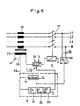
- FIG. 5 A more detailed embodiment of the invention can be seen in FIG. 5.
- the phase conductors L 1 ' L 2 , L 3 and the neutral conductor N, which are passed through the summation current transformer 10 as primary windings, can be seen again.
- the energy storage position which is indicated by a timer 13 and a threshold switch or a trigger circuit 14, adjoins the secondary winding 11.
- the output of the circuit 13/14 is connected to the relay 15 and then, when alternating fault currents occur, the capacitor 13 is charged and discharged via a threshold switch 14 to the relay 15, whereby the contact pieces 17 open.
- a rectifier 30 is connected via the lines 18 to the phase conductors L 1 and N, which rectifier 30 serves to supply the electronics circuit 19 framed by dashed lines.
- This electronic circuit essentially has an amplifier part 31, a timing element or an integrator 32 and a threshold switch 33 and an oscillator 34.
- the total current transformer 10 is connected to a tap 36 of the secondary winding 11 at a frequency of preferably 500 Hz - or demagnetized, according to the hysteresis loop of the material of the summation current transformer. If a DC fault current or an AC fault current with DC components occurs, the summation current transformer moves in the direction of saturation, i.e. in the asymmetry and the voltage drop that occurs is detected and processed via the circuit arrangement 31/32/33 and fed to the energy storage circuit 13/14, which triggers of the relay 15 and thus an opening of the contact points 17 is effected.
- a frequency of 1000 to 5000 Hz is essentially used to pre-magnetize the core. So that such a residual current circuit breaker can also detect AC residual currents, a second total current transformer is usually to be provided, see, for example, DE - PS - 23 48 881. Because the frequency of the oscillator is reduced to approx. 500 Hz, the total current transformer suitable for AC residual currents can also be used ; if the converter is made of F80 material, 700 turns are required on the secondary side and the tapping takes place approximately at a number of turns of 100, so that there are 35 100 turns of the secondary winding between the connection 40 and the tap line.
Landscapes
- Engineering & Computer Science (AREA)
- Power Engineering (AREA)
- Emergency Protection Circuit Devices (AREA)
- Driving Mechanisms And Operating Circuits Of Arc-Extinguishing High-Tension Switches (AREA)
- Protection Of Generators And Motors (AREA)
- Breakers (AREA)
- Switches With Compound Operations (AREA)
- Lock And Its Accessories (AREA)
- Push-Button Switches (AREA)
- Amplifiers (AREA)
- Interface Circuits In Exchanges (AREA)
- Keying Circuit Devices (AREA)
Abstract
Description
Die Erfindung betrifft einen Fehlerstromschutzschalter.The invention relates to a residual current circuit breaker.
Den Anstoß zur Erfindung gibt die Erfahrung, die bei der Anwendung der Fehlerstromschutzschaltung gemacht worden ist und die nach neuen technischen Lösungen verlangt, um die bekannt gewordenen Lücken im Schutzumfang dieser heute in vielen Ländern angewendeten Schutzmaßnahme zu schließen.The impetus for the invention is given by the experience which has been gained in the use of the residual current circuit and which calls for new technical solutions in order to close the known gaps in the scope of this protective measure which is used in many countries today.
Die für die Konstruktion von Fehlerstromschutzschaltern möglichen drei Grundschaltungen wurden schon vor zwanzig Jahren angegeben (1). Die zuerst in Österreich angewendeten FI-Schutzschalter mit Impuls- oder Energiespeicherauslösung, eine richtungsweisende Erfindung (AT-PS-197 368), wurden in großen Stückzahlen eingebaut und haben sich als zuverlässig erwiesen. Als Schaltorgan der Energiespeicherschaltung wurde zuerst eine Glimmlampe verwendet, wodurch diese Lösung kostspielig war (hohe Sekundärwindungszahl beim Summenstromwandler) und zuviel Raum in Anspruch nahm. Die Halbleitertechnik stellt aber heute geeignete Bauelemente zur Verfügung, die billig und mit kleinen Abmessungen die Glimmlampe als Schaltelement ersetzen können. Mit Schaltspannungen, die bei 10 Volt liegen, ermöglichen sie verhältnismäßig kleine Sekundärwindungszahlen des Summenstromwandlers und fast beliebige Auslösekennlinien des Schutzschalters. Um auch den Speicherkondensator klein zu halten, werden als Auslöser vorteilhaft polarisierte Permanentmagnetauslöser eingesetzt, die man weniger kritisch einstellen und mit größeren Auslösekräften arbeiten lassen kann als bei den netzspannungsunabhängigen Schaltungen ohne elektrische Energiespeicherung. Ein modernes Konzept eines Fehlerstromschutzschalters muß aber auch die Auslösung bei Fehlerströmen beherrschen, die in Form von pulsierenden oder geglätteten Gleichströmen auftreten können. Es war ja immer bekannt, daß FI-Schutzschalter nur bei Fehlerwechselströmen wirksam sein können. Hat der Fehlerstrom Gleichstromkomponenten, dann werden die Schutzschalter in ihrer Auslöseempfindlichkeit ungünstig beeinflußt. Da immer mehr elektronische Bauelemente in Haushaltsgeräten verwendet werden, muß auch das Gleichstromproblem gelöst werden. Man hat lange Zeit geglaubt, daß bei den in der Praxis bei elektrischen Haushaltsgeräten verwendeten Schaltungen im Falle eines Masseschlusses der fließende Fehlerstrom immer nur in Form eines pulsierenden Gleichstromes auftreten kann. Für derartige Fehlerströme, wie sie z.B. bei der Einweggleich-richtung ohne Glättungskondensator auftreten,, ist es möglich, Fehlerstromschutzschalter netzspannungsunabhängig mit den klassischen Schaltungen, also auch mit der Energiespeicherauslösung zu bauen (GB-PS-2 082 408 B). Es zeigte sich aber, daß es kaum möglich ist, den Herstellern von Elektrogeräten wegen der FI-Schutzschalter Beschränkungen in der Auswahl der für ihre Geräte notwendigen elektronischen Schaltungen aufzuerlegen. Besonders die Einweggleichrichtungen mit Glättungskondensatoren und die Drehstromgleichrichtungen müssen in diesem Zusammenhang genannt werden.The three basic circuits possible for the construction of residual current circuit breakers were specified twenty years ago (1). The residual current operated circuit breakers with pulse or energy storage release, a trend-setting invention (AT-PS-197 368), first used in Austria, were installed in large quantities and have proven to be reliable. A glow lamp was first used as the switching element of the energy storage circuit, which made this solution expensive (high number of secondary turns in the summation current transformer) and took up too much space. However, semiconductor technology today provides suitable components that can replace the glow lamp as a switching element cheaply and with small dimensions. With switching voltages of 10 volts, they enable relatively small numbers of secondary windings of the summation current transformer and almost any tripping characteristic of the circuit breaker. In order to keep the storage capacitor small, polarized permanent magnet triggers are advantageously used as triggers, which can be set less critically and can be operated with greater tripping forces than in the case of circuits independent of the mains voltage without electrical energy storage. However, a modern concept of a residual current circuit breaker must also be capable of triggering residual currents that can occur in the form of pulsating or smoothed direct currents. It was always known that residual current circuit breakers can only be effective with fault AC currents. If the fault current has direct current components, the tripping sensitivity of the circuit breakers is adversely affected. As more and more electronic components are used in household appliances, the DC problem must also be solved. It has long been believed that in the circuits used in practice in electrical household appliances, in the event of a ground fault, the flowing fault current can only ever occur in the form of a pulsating direct current. For such fault currents, e.g. occur in the one-way rectification without smoothing capacitor, it is possible to build residual current circuit breakers independent of the mains voltage using the classic circuits, i.e. also with the energy storage release (GB-PS-2 082 408 B). However, it was found that it is hardly possible to impose restrictions on the manufacturers of electronic devices because of the RCCBs in the selection of the electronic circuits necessary for their devices. In particular, the one-way rectifiers with smoothing capacitors and the three-phase rectifiers must be mentioned in this context.
Netzspannungsunabhängige Schaltungen, auch solche mit elektrischer Energiespeicherung, können aber wegen des transformatorischen Auslöseprinzips Fehlerströme in Form von geglätteten Gleichströmen nicht erkennen. In diesem Fall ist die Anwendung von Elektronikschaltungen erforderlich, die naturgemäß von der Netzspannung abhängen und über Summenstromwandler Fehlergleichströme in allen Formen verarbeiten können.Circuit-independent circuits, including those with electrical energy storage, cannot detect fault currents in the form of smoothed direct currents due to the transformer-based triggering principle. In this case, the use of electronic circuits is necessary, which naturally depend on the mains voltage and can process residual DC currents in all forms via summation current transformers.
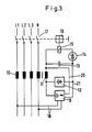
So beschreiben z.B. die US-Patentschrift 3,768,011 und die Offenlegungsschrift DE-OS-27 30 874 derartige Schaltungen. Es tritt also die Frage auf, welche Gefahren durch die Verwendung des Netzes als Hilfsspannungsversorgung für die Auslösung von Fehlerstromschutzschaltern entstehen können. Wird die Hilfsspannung nur von einem Außenleiter und dem Neutralleiter genommen, dann kann der Schalter versagen, wenn der entsprechende Außenleiter oder der Neutralleiter ausfällt (etwa beim Ansprechen einer Sicherung des Außenleiters oder beim Neutralleiterbruch), und Fehlerspannungen, die durch Masseschlüsse der beiden anderen Außenleiter entstehen, können nicht mehr erkannt werden. Aber auch wenn alle drei Außenleiter eines Drehstromnetzes für die Hilfsspannungsversorgung verwendet werden, bleibt immer noch der Neutralleiterbruch. Es wurde deshalb versucht, dadurch Abhilfe zu schaffen, daß der Fl-Schalter bei Neutralleiterbruch auslöst (DE-OS-28 25 881). Wenn man dafür einen zusätzlichen Anschluß, z.B. den Schutzleiter verwendet, dann hat dies den Nachteil, daß dadurch . die Installation komplizierter und das Erdpotential in den Schalter gebracht wird. Dadurch wird aber die Schaltung empfindlicher gegen Überspannungen, die ja vor allem gegen Erde auftreten. Netzspannungsabhängige Auslösungen haben aber vor allem den Nachteil, daß bei Masseschlüssen in der geschützten Anloge die Höhe der Spannung für die Hilfsspannungsversorgung vom Verhältnis des Netzschleifenwiderstandes zwischen Transformator und den Anschlußpunkten der Hilfsspannungsversorgung zum Gesamtwiderstand der Fehlerschleife abhängt. Dies ist in Figur 1 für den Fall des Masseschlusses in einer genullten Anlage dargestellt.For example, describe US Pat. No. 3,768,011 and DE-OS-27 30 874 disclose such circuits. So the question arises, what dangers can arise from using the network as an auxiliary voltage supply for triggering residual current circuit breakers. If the auxiliary voltage is only taken from one phase conductor and the neutral conductor, the switch can fail if the corresponding phase conductor or the neutral conductor fails (e.g. when a fuse of the phase conductor responds or if the neutral conductor breaks), and fault voltages that result from ground faults of the other two phase conductors , can no longer be recognized. But even if all three outer conductors of a three-phase network are used for the auxiliary voltage supply, the neutral conductor break still remains. An attempt was therefore made to remedy this by triggering the Fl switch in the event of a neutral conductor break (DE-OS-28 25 881). If you have an additional connection, e.g. used the protective conductor, this has the disadvantage that it. the installation is complicated and the earth potential is brought into the switch. However, this makes the circuit more sensitive to overvoltages, which occur above all to earth. Mains-voltage-dependent triggers have the disadvantage that in the event of a ground fault in the protected analogue, the level of the voltage for the auxiliary voltage supply depends on the ratio of the network loop resistance between the transformer and the connection points of the auxiliary voltage supply to the total resistance of the fault loop. This is shown in Figure 1 in the event of a short to ground in a zeroed system.
Bezeichnet man mit
- ZL die Leitungsimpedanz des Außenleiters vom Transformator bis zum Fehlerstromschutzschalter,
- ZPEN die Leitungsimpedanz des PEN-Leiters vom Transformator bis zum Fehlerstromschutzschalter
- Z1 Leitungsimpedanz des Außenleiters nach dem Fehlerstromschutzschalter bis zur Fehlerstelle
- Z2 Leitungsimpedanz des Schutzleiters von der Fehlerstelle bis zum PEN-Leiter UN Netzspannung-Außenleiter-PEN-Leiter
- Ua Versorgungsspannung der netzspannungsabhängigen Elektronikschaltung dann gilt für die Höhe der Versorgungsspannung
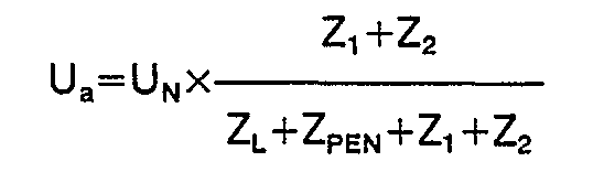
- Z L the line impedance of the outer conductor from the transformer to the residual current circuit breaker,
- Z PEN the line impedance of the PEN conductor from the transformer to the residual current circuit breaker
- Z 1 line impedance of the phase conductor after the residual current circuit breaker up to the fault location
- Z 2 Line impedance of the protective conductor from the fault point to the PEN conductor U N Mains voltage outer conductor PEN conductor
- U a supply voltage of the mains voltage-dependent electronic circuit then applies to the level of the supply voltage
Erfolgt also der Masseschluß in der Nähe der Einbaustelle des FI-Schalters, dann kann die Hilfsspannung zu Null werden, womit eine Auslösung unmöglich wird. In diesen Fällen müssen dann die Überstromschutzorgane den Masseschluß wegschalten, der FI-Schalter ist funktionslos geworden. Aus diesem Grund wird in Ländern, die Schalter mit netzspannungsabhängigen Auslösesystemen verwenden, durch den FI-Schutz nur der sogenannte Zusatzschutz erreicht und entsprechende Einschränkungen sind im internationalen Vorschriftenwesen geplant (2, 3).If there is a short to ground near the installation location of the RCD, the auxiliary voltage can become zero, making tripping impossible. In these cases, the overcurrent protection devices must switch off the short to ground, the FI switch has become inoperative. For this reason, in countries that use switches with line-voltage-dependent tripping systems, only the so-called additional protection is achieved through FI protection and corresponding restrictions are planned in international regulations (2, 3).
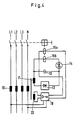
Es nützt auch nichts, wenn, wie in der DE―OS―28 25 881 angegeben, die Spannung des Neutralleiters gegen den Schutzleiter überwacht wird. Die Schaltung versagt nämlich, wenn zugleich mit dem Masseschluß ein Kurzschluß auftritt. Wie aus Figur 2 ersichtlich sind in diesem Fall die Ausgangsklemmen des FI-Schalters mit dem Schutzleiter zusammen kurzgeschlossen, der Schalter kann nicht auslösen und trotzdem nehmen die geschützten Anlagenteile eine Fehlerspannung von z.B. 110 Van.It is also of no use if, as stated in DE - OS - 28 25 881, the voltage of the neutral conductor is monitored against the protective conductor. The circuit fails if a short circuit occurs at the same time as the short to ground. In this case, as can be seen from FIG. 2, the output terminals of the RCD switch are short-circuited to the protective conductor, the switch cannot trip, and yet the protected system parts take on an error voltage of, for example, 110 Van.
Man erkennt dies auf Figur 2 mit den Bezeichnungen
- ZL' Leitungsimpedanz des Außenleiters vom Transformator bis zum Fehlerstromschutzschalter
- ZN' Leitungsimpedanz des Neutralleiters vom Transformator bis zum Fehlerstromschutzschalter
- ZL" Leitungsimpedanz des Außenleiters vom Fehlerstromschutzschalter bis zur Kurzschlußstelle
- ZN" Leitungsimpedanz des Neutralleiters vom Fehlerstromschutzschalter bis zur Kurzschlußstelle
- UN Netzspannung Außenleiter- Neutralleiter
- Ua Versorgungsspannung der netzspannungsabhängigen Elektronikschaltung
- PE Anschlußklemme für den Schutzleiter im Fehlerstromschutzschalter
- Ik Kurzschlußstrom
- I" Fehlerstrom
- RA Erdungswiderstand der geschützten Anlage
- RB Erdungswiderstand des Neutralleiters in der Transformatorenstation (Betriebserde)
- Z L 'Line impedance of the outer conductor from the transformer to the residual current circuit breaker
- Z N 'Line impedance of the neutral conductor from the transformer to the residual current circuit breaker
- Z L "Line impedance of the outer conductor from the residual current circuit breaker to the short circuit point
- Z N "Line impedance of the neutral conductor from the residual current circuit breaker to the short circuit point
- U N Line voltage outer conductor neutral conductor
- U a supply voltage of the mains voltage-dependent electronic circuit
- PE connection terminal for the protective conductor in the residual current circuit breaker
- I k short-circuit current
- I " fault current
- R A Earth resistance of the protected system
- R B earth resistance of the neutral conductor in the transformer station (operating earth)

- 1) Der Schalter muß bei normaler Netzspannungsversorgung bei Auftreten von Fehlerwechsel- und/oder Fehlergleichströmen auslösen. Löst er bei Fehlerwechselströmen beim Nennwert des Auslösefehlerstromes l△n aus, dann genügt es aus physiologischen Gründen (4), wenn die Auslösung bei pulsierenden Fehlergleichströmen bei Einweggleichrichtung bei √2xl△n, bei Vollweggleichrichtung bei 2xl△n und bei geglättetem Fehlergleichstrom bei 2,8xl△n erfolgt. Um dies zu erreichen sind netzspannungsabhängige Elektronikschaltungen erforderlich. Andere Hilfsspannungsquellen, z.B. Batterien, scheiden für diesen Verwendungszweck aus praktischen Gründen aus.
- 2) Der Schalter muß auch bei Ausfall der Außenleiter und/oder des Neutralleiters sowie bei gleichzeitigen Kurz- und Masseschlüssen bei Fehlerwechselströmen auslösen. Er braucht in diesen Fällen bei Fehlergleichströmen nicht funktionsfähig zu bleiben, weil erstens das gleichzeitige Auftreten einer Netzstörung und eines Fehlergleichstromes ein vernachlässigbares Sicherheitsrisiko darstellt und zweitens bei Kurzschlüssen die Fehlerspannung infolge der Spannungsteilung Außenleiter-Neutralleiter in Netzen bis 240 V gegen Erde unter 120 V bleibt und damit die konventionelle Berührungsspannungsgrenze, die bei Gleichstrom 120 V beträgt, nicht überschritten wird.
- 1) With normal mains voltage supply, the switch must trip if fault alternating and / or fault direct currents occur. If it triggers at fault AC currents at the nominal value of the tripping fault current l △ n , it is sufficient for physiological reasons (4) if the tripping in the case of pulsating fault DC currents with one-way rectification at √2xl △ n, with full path rectification at 2xl △ n and with smoothed fault DC current at 2, 8xl △ n takes place. To achieve this, line voltage-dependent electronic circuits are required. Other auxiliary voltage sources, such as batteries, are ruled out for this purpose for practical reasons.
- 2) The switch must also trip in the event of a failure of the outer conductor and / or the neutral conductor as well as in the event of short-circuit and earth faults in the event of fault AC currents. In these cases, it does not need to remain functional in the event of DC faults because, firstly, the simultaneous occurrence of a mains fault and a DC fault represents a negligible safety risk, and secondly, in the event of short circuits, the fault voltage due to the voltage division of the phase conductor-neutral conductor in networks up to 240 V against earth remains below 120 V and so that the conventional contact voltage limit, which is 120 V for direct current, is not exceeded.
Netzspannungsunabhängige Schaltungen können, wie erläutert, geglättete Gleichströme nicht erkennen, netzspannungsabhängige Konstruktionen versagen wieder bei Ausfall der Außenleiter und/oder des Neutralleiters und bei mit Masseschlüssen gleichzeitig auftretenden Kurzschlüssen. Die technischen Forderungen hinsichtlich des Schutzes bei indirektem Berühren schließen sowohl netzspannungs unabhängige Schaltungen als auch netzspannungsabhängige Schaltungen aus. Diese scheinbar widersprüchlichen Forderungen an einen Fehlerstromschutzschalter für den Schutz bei indirektem Berühren (Fehlerschutz) löst mit günstigen wirtschaftlichem Aufwand die im folgenden beschriebene Erfindung.As explained, circuits that are independent of the mains voltage cannot detect smoothed direct currents; constructions that are dependent on the mains voltage fail again in the event of failure of the outer conductor and / or the neutral conductor and in the event of short circuits occurring at the same time with ground faults. The technical requirements with regard to protection against indirect contact exclude circuits that are independent of the mains voltage as well as circuits that are dependent on the mains voltage. These apparently contradictory requirements for a residual current circuit breaker for protection against indirect contact (fault protection) are solved by the invention described below with favorable economic outlay.
Es wäre natürlich möglich, zwei FI-Schalter in Serie zu verwenden, einen mit netzspannungsunabhängiger Schaltung zur Erfüllung der unter 2) genannten Schutzbedingung und eine netzspannungsabhängige Konstruktion für die Schutzbedingungen, die in 1) angeführt wurden. Dieser Aufwand ist wirtschaftlich nicht zu vertreten. Auch der Einbau der beiden Systeme in einen Schalter mit zwei Summenstromwandlern und/ oder zwei Fehlerstromauslösern ist aus wirtschaftlichen Gründen und wegen des Platzbedarfes nicht möglich. Dies ist der Grund weshalb das Patent DE-PS-23 48 881 nie in der Praxis angewendet wurde. Es beschreibt einen Fehlerstromschutzschalter mit einer Summenstromwandleranordnung mit einer Sekundärwicklung, die mit der Erregerwicklung des Fehlerstromauslösers verbunden ist, wobei in der Sekundärwicklung von einer äußeren Wechselstromquelle ein Ruhestrom zum Vormagnetisieren des Wanderkerns eingespeist wird, wobei als kennzeichnend beschrieben wird, daß zusätzlich eine weitere, gesonderte Summenstromwandleranordnung mit einer der ersten Summenstromwandleranordnung entsprechenden Anzahl von Primärwicklungen und mit einer auf das der ersten Summenstromwandieranordnung zugeordnete Schaltschloß einwirkenden Sekundärwicklung angeordnet ist. Kennzeichnend für dieses Patent ist also die Verwendung von zwei Summenstromwandlern, und dies war eben der Grund, warum dieses Patent keine praktische Bedeutung erlangt hat.It would of course be possible to use two RCDs in series, one with a circuit independent of the mains voltage to meet the protection condition mentioned under 2) and a mains voltage dependent construction for the protection conditions listed in 1). This effort is not economically justifiable. The installation of the two systems in a switch with two summation current transformers and / or two residual current releases is not possible for economic reasons and because of the space requirement. This is the reason why the patent DE-PS-23 48 881 has never been applied in practice. It describes a residual current circuit breaker with a summation current transformer arrangement with a secondary winding, which is connected to the field winding of the residual current release, a quiescent current for biasing the core of the core being fed from an external AC power source, whereby it is described as characteristic that an additional, separate summation current transformer arrangement is additionally described is arranged with a number of primary windings corresponding to the first summation current transformer arrangement and with a secondary winding acting on the switching lock assigned to the first summation current conversion arrangement. The characteristic of this patent is therefore the use of two summation current transformers, and this is precisely the reason why this patent has no practical significance.
Aus der EP―OS―O 113 026 ist ein Fehlerstromschutzschalter bekannt geworden, bei dem ein Relais lediglich über eine Gleichrichterschaltung mit der Sekundärwicklung des Summenstromwandlers verbunden ist. Zur Erhöhung der Empfindlichkeit der Auslöseschaltung kann ein Kondensator verwendet werden, der mit der in der Auslöseschaltung befindlichen Induktivität (Relais bzw. Sekundärwicklung) einen auf die sekundärseitige Frequenz abgestimmten LC-Kreis bildet. Eine Energiespeicherschaltung ist diese bekannte Schaltung nicht.A residual current circuit breaker is known from EP - OS - O 113 026, in which a relay is only connected to the secondary winding of the summation current transformer via a rectifier circuit. To increase the sensitivity of the trigger circuit, a capacitor can be used which, together with the inductance (relay or secondary winding) located in the trigger circuit, forms an LC circuit which is tuned to the secondary frequency. This known circuit is not an energy storage circuit.
Auch aus der US―PS―4 320 433 ist eine Energiespeicherschaltung nicht bekanntgeworden.Also from the US - PS - 4,320,433 is unknown become an energy storage circuit.
Aus der FR-A-2416 580 ist ein Fehlerstromschutzschalter bekanntgeworden, der einen Fehlerauslöser, einen Summenstromwandler, eine netzspannungsunabhängige und eine netzspannungsabhängige Elektronikschaltung aufweist, wobei letztere einen Oszillator enthält, der eine Spannung in einer Wicklung des Summenstromwandlers erzeugt, und einen Gleichfehlerstromdetektor. Die spannungsunabhängige Elektronikschaltung ist mit einem Wechselfehlerstromdetektor versehen, der beim Auftreten von Fehlerwechselströmen anspricht und den Fehlerauslöser ansteuert. Treten Gleichfehlerströme auf, so simuliert der Gleichfehlerstromdetektor einen Kurzschluß zwischen Phase und Mp, woraufhin der Wechselfehlerstromdetektor-anspricht und den Fehlerauslöser betätigt. Dabei werden für beide Fehlerstromarten nur ein Summenstromwandler und ein Fehlerauslöser eingesetzt.A residual current circuit breaker has become known from FR-A-2416 580, which has a fault release, a summation current transformer, a mains voltage-independent and a mains voltage-dependent electronic circuit, the latter containing an oscillator that generates a voltage in a winding of the summation current transformer, and a direct current fault detector. The voltage-independent electronic circuit is equipped with an AC residual current detector, which responds when fault AC currents occur and controls the fault trigger. If DC residual currents occur, the DC residual current detector simulates a short circuit between phase and Mp, whereupon the AC residual current detector - responds and actuates the error trigger. Only one summation current transformer and one fault release are used for both types of fault current.
Aufgabe der Erfindung ist es daher, einen Fehlerstromschutzschalter der in der DE-A-2825881 genannten Art zu schaffen, der sowohl für Wechselfehler- als auch für Gleichfehlerströme sowie für Wechselfehlerströme mit Gleichstromkomponente gleichgut geeignet und dabei einfach in seinem Aufbau ist.The object of the invention is therefore to provide a residual current circuit breaker of the type mentioned in DE-A-2825881, which is equally suitable for alternating fault and direct fault currents as well as for alternating fault currents with a direct current component and is simple in its construction.
Diese Aufgabe wird erfindungsgemäß durch die Merkmale des Anspruches 1 gelöst.This object is achieved by the features of
Die Sekundärwicklung des Summenstromwandlers dient sowohl für die Aufladung des Speicherkondensators bei netzspannungsunabhängiger Auslösung beim Auftreten von Fehlerwechselströmen bzw. pulsierenden Fehlergleichströmen, als auch zur Steuerung der Elektronikschaltung, mit der glatte Fehlergleichströme oder aber auch pulsierende Fehlergleichströme erfaßt werden, falls die Energiespeicherschaltung nurfür Fehlerwechselströme ausgelegt ist. Versieht man den Summenstromwandler mit einer Sekundärwicklung und einerTertiärwicklung, dann kann die Sekundärwicklung für die Energiespeicherschaltung und die Tertiärwicklung für die Steuerung der Elektronikschaltung verwendet werden. Durch diese Lösung kann man die Energiespeicherschaltung galvanisch von der Elektronikschaltung trennen, wenn man den Fehlerstromauslöser mit zwei Auslösespulen versieht.The secondary winding of the summation current transformer is used both for charging the storage capacitor in the event of tripping independent of the mains voltage when fault AC currents or pulsating DC fault currents occur, and for controlling the electronic circuit with which smooth DC fault currents or pulsating DC fault currents are detected if the energy storage circuit is designed only for AC fault currents. If the summation current transformer is provided with a secondary winding and a tertiary winding, the secondary winding can be used for the energy storage circuit and the tertiary winding for the control of the electronic circuit. With this solution, the energy storage circuit can be galvanically separated from the electronic circuit if the residual current release is provided with two release coils.
Eine weitere Beeinflussung der Auslösekennlinie des FI-Schutzschalters ist auf einfache und bekannte Weise (AT―PS―205 574) dadurch möglich, daß über die Elektronikschaltung in der Sekundär- oder Tertiärwicklung des Summenstromwandlers dauernd ein künstlicher Fehlerstrom erzeugt wird, der unter der Ansprechgrenze des Schutzschalters liegt. Der Summenstromwandler wird dann auch durch diesen Fehlerstrom vorerregt und der Speicherkondensator dadurch teilweise aufgeladen. Entsteht nun in der Anlage ein echter Fehlerstrom, der den Auslösestrom des Schalters überschreitet, so bewirkt dieser die restliche Aufladung des Speicherkondensators bis zum Ansprechen der Energiespeicherschaltung.A further influencing of the tripping characteristic of the residual current circuit breaker is possible in a simple and known manner (AT - PS - 205 574) in that an artificial fault current is continuously generated in the secondary or tertiary winding of the summation current transformer, which is below the response limit of the Circuit breaker. The residual current transformer is then also pre-excited by this fault current and the storage capacitor is thereby partially charged. If a real fault current arises in the system that exceeds the tripping current of the switch, this causes the remaining charging of the storage capacitor until the energy storage circuit responds.
Dies kann dadurch erreicht werden, daß der durch die netzspannungsabhängige Elektronikschaltung erzeugte Signalstrom mit geeigneter Frequenz, der ja über die Sekundär- oder Tertiärwicklung des Summenstromwandlers fließt, diese induziert und damit über die Gleichrichterschaltung die Energievorspeicherung des Speicherkondensators bewirkt.This can be achieved in that the signal current generated by the mains voltage-dependent electronic circuit with a suitable frequency, which flows through the secondary or tertiary winding of the summation current transformer, induces it and thus causes the energy storage of the storage capacitor via the rectifier circuit.
Anhand der Zeichnung, in der dem Stand der Technik zugehörige Schaltungen un Ausführungsbeispiele der Erfindung dargestellung sind, soll die Erfindung näher erläutert und beschrieben werden.The invention is to be explained and described in more detail with reference to the drawing, in which circuits related to the prior art and exemplary embodiments of the invention are shown.
Fig. 1 und 2 zwei bekannte Schaltungen, die schon oben beschrieben sind,1 and 2, two known circuits, which have already been described above,
Fig. 3, 4 und 5 je ein Ausführungsbeispiel eines erfindungsgemäßen Fehlerstromschutzschalters.3, 4 and 5 each show an embodiment of a residual current circuit breaker according to the invention.
Die Phasenleiter Li, L2, L3 und der Neutralleiter N eines Netzes sind als Primärwicklungen durch einen Summenstromwandler 10 hindurchgeführt. Der Summenstromwandler 10 trägt eine Sekundärwicklung 11, an der eine Gleichrichterschaltung 12 angeschlossen ist, der ein als Kondensator 13 ausgebildeter Energiespeicher parallel geschaltet ist, welcher Kondensator 13 nach Erreichen einer bestimmten Ladespannung einen Schwellwertschalter 14 durchschaltet. Parallel zu dem Energiespeicher 13 ist ein Permanentmagnetauslöser 15 geschaltet, der ein Schaltschloß 16 auslöst, das Kontaktstücke 17 in den Leitern L1 bis L3 und N öffnet. Über Versorgungsleitungen 18, die mit dem Phasenleiter L1 und dem Neutralleiter N verbunden sind, wird eine elektronische Erfassungseinrichtung 19 mit Spannung versorgt, die Gleichfehlerströme an der Sekundärwicklung erfaßt und über Verbindungsleitungen 20 und 21 mit dem Energiespeicher verbunden ist.The phase conductors L i , L 2 , L 3 and the neutral conductor N of a network are passed through a summation
Die Sekundärwicklung 11 dient damit sowohl für die Aufladung des Kondensators 13 beim Fließen von Fehlerwechselströmen und ggf. auch bei pulsierenden Fehlergleichströmen, als auch zur Steuerung der netzspannungsabhängigen Elektronikschaltung 19, die beispielhaft so gestaltet ist, daß sie parallel zum Kondensator 13 liegt, also auch beim Ansprechen mit Auslöseimpulsen über das spannungsabhängige Halbleiterelement 14 und die Auslösespule des Fehlerstromauslösers 15 arbeitet.The secondary winding 11 thus serves both for charging the
Die Schalteranordnung nach Figur 4 unterscheidet sich von der nach Figur 3 nur dadurch, daß der Summenstromwandler 10 eine Sekundärwicklung 11 und eine Tertiärwicklung 22 besitzt, wobei die Sekundärwicklung für die Energiespeicherschaltung und die Tertiärwicklung 22 für die Steuerung der Elektronikschaltung verwendet wird. Der Fehlerstromauslöser 15 besitzt beispielsweise zwei Auslösespulen 15a und 15b. Dadurch ist der Auslösekreis der Energiespeicherschaltung galvanisch vom Auslösekreis der Elektronisschaltung und damit auch vom Netz getrennt.The switch arrangement according to FIG. 4 differs from that according to FIG. 3 only in that the summation
Eine detaillierterer Ausgestaltung der Erfindung ist in Figur 5 zu entnehmen. Man erkennt wieder die Phasenleiter L1' L2, L3 sowie den Neutralleiter N, die als Primärwicklungen durch den Summenstromwandler 10 hindurchgeführt sind. An der Sekundärwicklung 11 schließt die Energiespeicherstellung an, die durch ein Zeitglied 13 und einen Schwellwertschalter oder eine Triggerschaltung 14 angedeutet ist. Der Ausgang der Schaltung 13/14 ist auf das Relais 15 aufgeschaltet und dann, wenn Wechselfehlerströme auftreten, wird der Kondensator 13 aufgeladen und bei einem bestimmten Ladezustand über den Schwellwertschalter 14 auf das Relais 15 entladen, wodurch die Kontaktstücke 17 öffnen. Über die Leitungen 18 ist ein Gleichrichter 30 mit dem Phasenleiter L1 und N verbunden, welcher Gleichrichter 30 zur Versorgung der strichliert eingerahmten Elektronikschaltung 19 dient. Diese Elektronikschaltung besitzt im wesentlichen ein Verstärkerteil 31, ein Zeitglied oder einen Integrator 32 und einen Schwellwertschalter 33 sowie einen Oszillator 34. Mittels des Oszillators wird über eine Leitung 35 an einer Anzapfstelle 36 der Sekundärwicklung 11 der Summenstromwandler 10 mit einer Frequenz von vorzugsweise 500 Hz auf- bzw. abmagnetisiert, entsprechend der Hystereseschleife des Materials des Summenstromwandlers. Bei Auftreten eines Gleichfehlerstromes bzw. eines Wechselfehlerstromes mit Gleichstromkomponenten fährt der Summenstromwandler in Richtung Sättigung, d.h. also in die Unsymmetrie und der dabei auftretende Spannungsabfall wird über die Schaltungsanordnung 31/32/33 erfaßt und verarbeitet und der Energiespeicherschaltung 13/14 zugeführt, wodurch eine Auslösung des Relais 15 und damit eine Öffnung der Kontaktstellen 17 bewirkt wird.A more detailed embodiment of the invention can be seen in FIG. 5. The phase conductors L 1 ' L 2 , L 3 and the neutral conductor N, which are passed through the summation
Bei den bekannten elektronischen Schaltungsanordnungen zur Erfassung von Gleichfehlerströmen wird im wesentlichen eine Frequenz von 1000 bis 5000 Hz benutzt, um den Kern vorzumagnetisieren. Damit ein derartiger Fehlerstromschutzschalter auch Wechselfehlerströme detektieren kann, ist meist ein zweiter Summenstromwandler vorzusehen, siehe z.B. die DE―PS―23 48 881. Dadurch, daß die Frequenz des Oszillators auf ca. 500 Hz heruntergesetzt wird, kann der für Wechselfehlerströme geeignete Summenstromwandler mitbenutzt werden; wenn dabei der Wandler aus F80-Material hergestellt wird, benötigt man 700 Windungen an der Sekundärseite und die Anzapfung erfolgt etwa bei einer Windungszahl von 100, so daß zwischen dem Anschluß 40 und der Anzapfleitung 35 100 Windungen der Sekundärwicklung liegen.In the known electronic circuit arrangements for detecting DC fault currents, a frequency of 1000 to 5000 Hz is essentially used to pre-magnetize the core. So that such a residual current circuit breaker can also detect AC residual currents, a second total current transformer is usually to be provided, see, for example, DE - PS - 23 48 881. Because the frequency of the oscillator is reduced to approx. 500 Hz, the total current transformer suitable for AC residual currents can also be used ; if the converter is made of F80 material, 700 turns are required on the secondary side and the tapping takes place approximately at a number of turns of 100, so that there are 35 100 turns of the secondary winding between the
- (1) Biegelmeier, G.: Moderner Fehlerstromschutz. E.u.M., 75. Jg. (1958), H.8, S. 157...164(1) Biegelmeier, G .: Modern residual current protection. E.u.M., 75th vol. (1958), H.8, pp. 157 ... 164
- (2) Biegelmeier, G.: Gedanken über die Nullung (TN-System) als optimalen Fehlerschutz (Schutzmaßnahme bei indirektem Berühren) in elektrischen Anlagen. ÖZE 37. Jg. (1984), H.12, S.483(2) Biegelmeier, G .: Thoughts about zeroing (TN system) as optimal error protection (protective measure against indirect contact) in electrical systems. ÖZE 37th vol. (1984), H.12, p.483
- (3) IEC 64 (Central Office) 151, January 1985, IEC Publ. 364 Part 5, Chapter 53 switchgear and controlgear(3) IEC 64 (Central Office) 151, January 1985, IEC Publ. 364 Part 5, Chapter 53 switchgear and controlgear
- (4) IEC-Report 479, second Edition: Effects of electric shock on the human body, Part 2, Chapter 5(4) IEC Report 479, second edition: Effects of electric shock on the human body, Part 2, Chapter 5
Claims (4)
Applications Claiming Priority (2)
| Application Number | Priority Date | Filing Date | Title |
|---|---|---|---|
| AT1137/85 | 1985-04-16 | ||
| AT0113785A AT383906B (en) | 1985-04-16 | 1985-04-16 | Fault current protection switch for fault change and fault current |
Publications (2)
| Publication Number | Publication Date |
|---|---|
| EP0218648A1 EP0218648A1 (en) | 1987-04-22 |
| EP0218648B1 true EP0218648B1 (en) | 1990-10-10 |
Family
ID=3507399
Family Applications (1)
| Application Number | Title | Priority Date | Filing Date |
|---|---|---|---|
| EP86902329A Expired - Lifetime EP0218648B1 (en) | 1985-04-16 | 1986-04-12 | Fault current protection circuit breaker |
Country Status (9)
| Country | Link |
|---|---|
| EP (1) | EP0218648B1 (en) |
| AT (2) | AT383906B (en) |
| AU (1) | AU597252B2 (en) |
| DE (1) | DE3674877D1 (en) |
| ES (1) | ES8703678A1 (en) |
| GB (1) | GB2176069B (en) |
| GR (1) | GR860989B (en) |
| NZ (1) | NZ215855A (en) |
| WO (1) | WO1986006222A1 (en) |
Families Citing this family (16)
| Publication number | Priority date | Publication date | Assignee | Title |
|---|---|---|---|---|
| US4685022A (en) * | 1985-05-10 | 1987-08-04 | Square D Company | Ground fault circuit interrupter capable of deriving energy from ground fault current in order to achieve circuit interruption in the presence of a reduced supply voltage |
| AT387675B (en) * | 1987-04-02 | 1989-02-27 | Cti Ges Zur Pruefung Elektrote | Fault current protection switch with short delay |
| AT398141B (en) * | 1987-09-15 | 1994-09-26 | Felten & Guilleaume Ag Oester | Switchgear combination |
| AT405114B (en) * | 1997-02-12 | 1999-05-25 | Felten & Guilleaume Ag Oester | ARROW DISCONNECTOR |
| DE29705030U1 (en) * | 1997-03-19 | 1998-07-23 | Siemens AG, 80333 München | Residual current circuit breaker for all-current |
| AT406431B (en) * | 1998-01-28 | 2000-05-25 | Felten & Guilleaume Ag Oester | DEVICE FOR ANALYZING EARTH FAULT CURRENTS APPLICABLE IN AN ELECTRICAL SYSTEM AND BY THIS CONTROLLED SWITCHGEAR |
| DE19943802A1 (en) * | 1999-09-13 | 2001-03-15 | Siemens Ag | AC / DC sensitive residual current protective device and method for detecting a residual current |
| EP1478068B1 (en) * | 2003-05-15 | 2010-06-30 | Siemens Aktiengesellschaft | All fault-current sensitive protection device |
| EP1478069B1 (en) | 2003-05-15 | 2010-07-14 | Siemens Aktiengesellschaft | All fault-current sensitive protection device |
| EP1478070B1 (en) * | 2003-05-15 | 2010-06-30 | Siemens Aktiengesellschaft | All fault-current sensitive protection device |
| ATE362670T1 (en) * | 2004-05-04 | 2007-06-15 | Gewiss Spa | PROTECTIVE DEVICE FOR AC AND DC RESIDUAL CURRENTS |
| DE102004043468A1 (en) * | 2004-09-08 | 2006-03-30 | Siemens Ag | Switchgear with pluggable connections |
| AT503541B1 (en) | 2006-04-20 | 2008-10-15 | Moeller Produktions Und Vertri | SWITCHING DEVICE |
| AT507202B1 (en) * | 2008-12-02 | 2010-03-15 | Moeller Gebaeudeautomation Gmb | FAULT CIRCUIT BREAKER |
| DE102015224890A1 (en) * | 2015-04-30 | 2016-11-03 | Siemens Aktiengesellschaft | Residual Current Device |
| FR3065110B1 (en) * | 2017-04-11 | 2019-04-19 | Schneider Electric Industries Sas | METHOD AND DEVICE FOR CONTROLLING AN ACTUATOR, AND ELECTRICAL PROTECTION APPARATUS COMPRISING SUCH A DEVICE |
Family Cites Families (16)
| Publication number | Priority date | Publication date | Assignee | Title |
|---|---|---|---|---|
| AT197468B (en) * | 1957-03-02 | 1958-04-25 | Biegelmeier Gottfried | Residual voltage or residual current protection circuit |
| AT205574B (en) * | 1958-06-25 | 1959-10-10 | Biegelmeier Gottfried | Residual current circuit breaker with pulse release and energy pre-storage |
| DE1808770A1 (en) * | 1968-11-14 | 1970-06-11 | Siemens Ag | Residual current circuit breaker |
| US3768011A (en) * | 1970-06-09 | 1973-10-23 | W Swain | Means for measuring magnitude and direction of a direct current or permanent magnet, including clip-on direct current sensing inductor |
| DE2348881C3 (en) * | 1973-09-28 | 1980-10-16 | Siemens Ag, 1000 Berlin Und 8000 Muenchen | Residual current circuit breaker |
| FR2321208A1 (en) * | 1975-08-11 | 1977-03-11 | Saparel | Detection of leakage current to earth - uses differential current transformer whose core is saturated by leakage current |
| DE2555302C3 (en) * | 1975-12-09 | 1982-02-25 | Brown, Boveri & Cie Ag, 6800 Mannheim | Residual current protection circuit |
| BE856056A (en) * | 1976-07-13 | 1977-12-23 | Hazemeijer Bv | CURRENT MEASUREMENT SYSTEM, MORE PARTICULARLY APPLICABLE AS EARTH LAKE DETECTION SYSTEM, AND FUNCTIONAL DEVICE EQUIPPED WITH A SUCH SYSTEM, SUCH AS A GND SWITCH |
| NL176508C (en) * | 1977-06-14 | 1985-04-16 | Hazemeijer Bv | NUTRITION EQUIPMENT FOR A PROTECTION DEVICE, SUCH AS AN EARTH DETECTION DEVICE, AND PROTECTION EQUIPMENT EQUIPPED WITH SUCH A NUTRITION EQUIPMENT. |
| LU78600A1 (en) * | 1977-11-28 | 1979-06-13 | Gath N | Fault current protection switch |
| LU78992A1 (en) * | 1978-02-02 | 1979-09-06 | N Gath | FAULT CIRCUIT BREAKER |
| JPS55127826A (en) * | 1979-03-26 | 1980-10-03 | Fuji Electric Co Ltd | Leakage breaker |
| US4320433A (en) * | 1980-03-21 | 1982-03-16 | Fuji Electric Co., Ltd. | Earth-leakage-current circuit breaker system |
| ATA426180A (en) * | 1980-08-21 | 1982-08-15 | Biegelmeier Gottfried | Fault current protection switch |
| DE3048785A1 (en) * | 1980-12-23 | 1982-07-15 | Brown, Boveri & Cie Ag, 6800 Mannheim | CIRCUIT ARRANGEMENT FOR DETECTING A FAULT CURRENT |
| DE3244670A1 (en) * | 1982-12-02 | 1984-06-07 | Siemens AG, 1000 Berlin und 8000 München | Fault current protection switch |
-
1985
- 1985-04-16 AT AT0113785A patent/AT383906B/en not_active IP Right Cessation
-
1986
- 1986-04-12 EP EP86902329A patent/EP0218648B1/en not_active Expired - Lifetime
- 1986-04-12 DE DE8686902329T patent/DE3674877D1/en not_active Expired - Lifetime
- 1986-04-12 WO PCT/DE1986/000161 patent/WO1986006222A1/en active IP Right Grant
- 1986-04-12 AT AT86902329T patent/ATE57448T1/en not_active IP Right Cessation
- 1986-04-12 AU AU57786/86A patent/AU597252B2/en not_active Ceased
- 1986-04-15 GR GR860989A patent/GR860989B/en unknown
- 1986-04-15 ES ES553997A patent/ES8703678A1/en not_active Expired
- 1986-04-16 NZ NZ215855A patent/NZ215855A/en unknown
- 1986-04-16 GB GB08609254A patent/GB2176069B/en not_active Expired
Also Published As
| Publication number | Publication date |
|---|---|
| GB2176069B (en) | 1988-11-23 |
| EP0218648A1 (en) | 1987-04-22 |
| ES8703678A1 (en) | 1987-02-16 |
| GR860989B (en) | 1986-07-21 |
| WO1986006222A1 (en) | 1986-10-23 |
| NZ215855A (en) | 1988-11-29 |
| AT383906B (en) | 1987-09-10 |
| AU597252B2 (en) | 1990-05-31 |
| GB8609254D0 (en) | 1986-05-21 |
| GB2176069A (en) | 1986-12-10 |
| ATE57448T1 (en) | 1990-10-15 |
| ES553997A0 (en) | 1987-02-16 |
| DE3674877D1 (en) | 1990-11-15 |
| ATA113785A (en) | 1987-01-15 |
| AU5778686A (en) | 1986-11-05 |
Similar Documents
| Publication | Publication Date | Title |
|---|---|---|
| EP0218648B1 (en) | Fault current protection circuit breaker | |
| DE68911861T2 (en) | Differential release with test circuit and with self-protecting remote control for opening. | |
| DE19735412A1 (en) | Fault-current protection device e.g. for protecting personnel against dangerous fault currents in electrical equipment | |
| DE2624316A1 (en) | Automatic AC mains switch - uses transformer monitor to disconnect entire house from street mains when all appliances are off | |
| DE102017217040A1 (en) | Residual current circuit breaker and method | |
| DE2847976A1 (en) | EARTH FAULT PROTECTIVE DEVICE FOR INDUSTRIAL POWER CIRCUITS | |
| EP0497752B1 (en) | Disconnection device for surge arresters | |
| DE1513295C3 (en) | ||
| EP0524142B1 (en) | Electronic trip circuit for earth leakage circuit breaker | |
| DE4040359C2 (en) | Short-circuit protection device | |
| DE1513295B2 (en) | DEVICE FOR PROTECTION AGAINST THE FAULT CURRENTS OF ELECTRICAL EQUIPMENT | |
| WO1986006563A1 (en) | Fault-current protection switch for a.c. and d.c. fault currents without energy storage | |
| DE3738493C2 (en) | Fault location device | |
| DE102020216414A1 (en) | RCDs and procedures | |
| EP1388191A1 (en) | Bypass circuit for the overcurrent trip of a low-voltage power circuit breaker | |
| EP1478070A1 (en) | All fault-current sensitive protection device | |
| DE19946098C2 (en) | RCD | |
| DE2611674C2 (en) | ||
| DE4124190A1 (en) | Network protection circuit for monitoring and isolating due to fault - measures current difference between at least one outgoing lead and neutral lead to detect fault or earth leakage | |
| EP0951046A2 (en) | Ground fault circuit breaker | |
| DE687519C (en) | Circuit for protection against impermissible contact voltages in low-voltage systems | |
| DE2713043C2 (en) | Residual current circuit breaker | |
| DE4429950A1 (en) | Semi automatic test facility for leakage current detection | |
| DE2613972A1 (en) | Earth leakage mains circuit breaker - has sum current transformer with winding compensating capacitive leakage currents for single or polyphase circuits | |
| DE10246479B4 (en) | Low voltage circuit breaker with additional quick trip |
Legal Events
| Date | Code | Title | Description |
|---|---|---|---|
| PUAI | Public reference made under article 153(3) epc to a published international application that has entered the european phase |
Free format text: ORIGINAL CODE: 0009012 |
|
| 17P | Request for examination filed |
Effective date: 19861208 |
|
| AK | Designated contracting states |
Kind code of ref document: A1 Designated state(s): AT BE CH DE FR LI LU NL SE |
|
| RAP1 | Party data changed (applicant data changed or rights of an application transferred) |
Owner name: ASEA BROWN BOVERI AKTIENGESELLSCHAFT |
|
| 17Q | First examination report despatched |
Effective date: 19890224 |
|
| GRAA | (expected) grant |
Free format text: ORIGINAL CODE: 0009210 |
|
| AK | Designated contracting states |
Kind code of ref document: B1 Designated state(s): AT BE CH DE FR LI LU NL SE |
|
| PG25 | Lapsed in a contracting state [announced via postgrant information from national office to epo] |
Ref country code: SE Effective date: 19901010 |
|
| REF | Corresponds to: |
Ref document number: 57448 Country of ref document: AT Date of ref document: 19901015 Kind code of ref document: T |
|
| ET | Fr: translation filed | ||
| REF | Corresponds to: |
Ref document number: 3674877 Country of ref document: DE Date of ref document: 19901115 |
|
| PGFP | Annual fee paid to national office [announced via postgrant information from national office to epo] |
Ref country code: SE Payment date: 19910222 Year of fee payment: 6 |
|
| PGFP | Annual fee paid to national office [announced via postgrant information from national office to epo] |
Ref country code: LU Payment date: 19910304 Year of fee payment: 6 |
|
| EPTA | Lu: last paid annual fee | ||
| PLBE | No opposition filed within time limit |
Free format text: ORIGINAL CODE: 0009261 |
|
| STAA | Information on the status of an ep patent application or granted ep patent |
Free format text: STATUS: NO OPPOSITION FILED WITHIN TIME LIMIT |
|
| 26N | No opposition filed | ||
| PG25 | Lapsed in a contracting state [announced via postgrant information from national office to epo] |
Ref country code: LU Free format text: LAPSE BECAUSE OF NON-PAYMENT OF DUE FEES Effective date: 19920412 |
|
| PGFP | Annual fee paid to national office [announced via postgrant information from national office to epo] |
Ref country code: FR Payment date: 19940210 Year of fee payment: 9 |
|
| PGFP | Annual fee paid to national office [announced via postgrant information from national office to epo] |
Ref country code: CH Payment date: 19940211 Year of fee payment: 9 |
|
| PG25 | Lapsed in a contracting state [announced via postgrant information from national office to epo] |
Ref country code: LI Effective date: 19950430 Ref country code: CH Effective date: 19950430 |
|
| REG | Reference to a national code |
Ref country code: CH Ref legal event code: PL |
|
| PG25 | Lapsed in a contracting state [announced via postgrant information from national office to epo] |
Ref country code: FR Effective date: 19951229 |
|
| PGFP | Annual fee paid to national office [announced via postgrant information from national office to epo] |
Ref country code: NL Payment date: 19960126 Year of fee payment: 11 |
|
| PGFP | Annual fee paid to national office [announced via postgrant information from national office to epo] |
Ref country code: BE Payment date: 19960202 Year of fee payment: 11 |
|
| REG | Reference to a national code |
Ref country code: FR Ref legal event code: ST |
|
| PG25 | Lapsed in a contracting state [announced via postgrant information from national office to epo] |
Ref country code: BE Effective date: 19970430 |
|
| BERE | Be: lapsed |
Owner name: ASEA BROWN BOVERI A.G. Effective date: 19970430 |
|
| PG25 | Lapsed in a contracting state [announced via postgrant information from national office to epo] |
Ref country code: NL Effective date: 19971101 |
|
| NLV4 | Nl: lapsed or anulled due to non-payment of the annual fee |
Effective date: 19971101 |
|
| PGFP | Annual fee paid to national office [announced via postgrant information from national office to epo] |
Ref country code: AT Payment date: 20010209 Year of fee payment: 16 |
|
| PGFP | Annual fee paid to national office [announced via postgrant information from national office to epo] |
Ref country code: DE Payment date: 20011129 Year of fee payment: 17 |
|
| PG25 | Lapsed in a contracting state [announced via postgrant information from national office to epo] |
Ref country code: AT Free format text: LAPSE BECAUSE OF NON-PAYMENT OF DUE FEES Effective date: 20020412 |
|
| PG25 | Lapsed in a contracting state [announced via postgrant information from national office to epo] |
Ref country code: DE Free format text: LAPSE BECAUSE OF THE APPLICANT RENOUNCES Effective date: 20030412 |